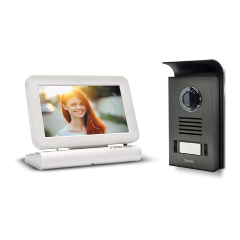
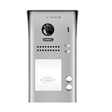
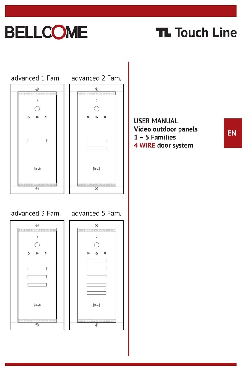
Bellcome Touch Line VPA.1FR03.BLB04 User manual

1DE
EN
FR
Sicherheitshinweise
Safety instructions
Instructions de sécurité
2DE
EN
FR
Kabel und Installation
Cables and installation
Câbles et installation
≈20cm
50mm
120mm
280mm (1-3 Fam.)
Mounting on the wall - Flush
4mm 50mm
Unmount the module and add the name labels.
Orientation of the video camera
130 cm 130 cm 130 cm
294 x 144 x 53 mm / 1,52 kg
BENUTZERHANDBUCH
Videoaußeneinheiten
DE
USER MANUAL
Video outdoor panels
EN
MANUEL D`UTILISATEUR
Panneaux extérieurs vidéo
FR
FLUSH mounting
o o
Aluminium-Case + Secured Glass ; IP 44; -30 C ... +80 C
CMOS 1.3” 800 TVL video camera
RFID card access
Operating voltage: 11 ... 14 Vd.c.
Stand-by current: 60 mAd.c. Summer / 130 mAd.c. Winter
Operating current: 220 mAd.c. Summer / 300 mAd.c. Winter
VPA.1FR03.BLB(W)04 VPA.2FR03.BLB(W)04 VPA.3FR03.BLB(W)04
1. Anhand des Kaufdokuments wird gemäß den geltenden Rechtsvorschriften eine Garantie von 24 Monaten
gewährt.
2. Für Fehler und / oder versteckte Mängel wird eine Garantie gewährt.
3. Die Garantie wird NICHT gewährt für: falsche, dem vorliegenden Bedienerhandbuch nicht entsprechende
Installation und/ oder Verwendung; zerbrochenes Glas, Schläge, mechanische Stöße; Diebstahl, Feuer,
Überschwemmungen, Naturkatastrophen; ungeschütztes Produkt bei Renovierungsarbeiten;
die RFID-Zugangskarten (Tags), die als Verbrauchsmaterialien gelten.
1. Une garantie de 24 mois est accordée conformément à la législation en vigueur, sur la base du document
d'achat.
2. La garantie s'applique en cas de non-conformités et / ou de défauts cachés.
3. La garantie N'EST PAS accordée pour: installation et/ ou fonctionnement incorrects, non conformes à ce
manuel; verre brisé, coups, chocs mécaniques ; vol, incendie, inondations, catastrophes naturelles;
produits non protégés lors des activités de rénovation ; les cartes d'accès RFID (tags), qui sont des
consommables.
DE
2
GarantieGarantie
FR
1. A 24-month warranty is granted, according to the existing legislation, based on the purchase document.
2. Warranty is granted for non-conformity and/or hidden defects.
3. Warranty is NOT granted for: incorrect installation and/ or operation, non-compliant with this manual;
broken glass, blows, mechanical shocks; theft, fire, floods, natural disasters; unprotected products during
renovation activities; the RFID access cards (tags), which are considered consumables.
Warranty
EN
+14
C/D
6mm
20-25mm
GND
Vin
+14
C/D
6mm 20-25mm
GND
Vout
Outdoor Panel Central unit
Standard 4 Wire
2 2
4 x 0.5 mm (max. 60m); 4 x 0.75 mm (max. 100m);
TCYY – 2x2x0.5-24 AWG (max. 30m);
TCYY – 3x2x0.5-24 AWG (max. 50m);
TCYY – 4x2x0.5-24 AWG (max. 50m)
UTP/FTP cat5e (AWG24) / cat6 (AWG23)
(max. 200m)
+14
C/D
GND
20-25mm
6mm
Vin
+14
C/D
GND
20-25mm
6mm
Vout
Outdoor Panel Central unit
Name 1
Name 1
Name 2
Name 1
Name 2
Name 3
Name 1
Name 2
Name 3

+14
C/D
GND
Vin
+14
C/D
GND
Vin
GONG
Doorbell
Fam. 1(Address 1)
GNG+
GNG-
DBL1
DBL2
06.2023 INS.VPA.3FR03.BLY04
SUPPORT
ELECTRA Building Communications GmbH
Gadnergasse 71, Stockwerk 1, Büro Top 132
1110 Wien - AT
www.bellcome.com
+43 1 810 20 99
MADE in EU by:
ELECTRA s.r.l
Parc Industrial Miroslava
Str. Principala 33, 707307, Jud. Iași - RO
+40 232 214.370
www.electra.ro
4DE Schaltpläne EN Connection diagrams FR Schémas de connexion
+14
C/D
GND
Vin
GROUNDED
OUTLET
+14
C/D
GND
Vout
+14
C/D
GND
Vin1
+14
C/D
GND
Vout1
EXT1
EXT2
LCK1
LCK2
-
+
LOCK
SUPPLY
EXIT
LOCK
max.12Ah/12V
+
-
BAT
110/230Va.c.
50/60Hz
Outdoor Panel
Vcam DVR AUX1AUX2
OTHER VIDEO CAMERA DVR AUX1 AUX2 OUT1 OUT2 OUT3
BAT
DOOR LOCK
LOCK
SUPPLY
VIDEO DOOR PANEL
+14
CD
GND
Vin1
GNV
EXIT
EXIT
LCK
LCK
NO NC
10 SEC
BAT
BAT
FUSE - T1.6A
Vout3
GND
CD
+14
Vout2
GND
CD
+14
Vout1
GND
CD
+14
GNV
AUX2
AUX2
AUX1
AUX1
OFF ON
GNV
Vout
+12
GND
Vin2
OFF ON
2 SEC
AC. 110/230V
SCU.VDR03.BLG14
OTHER VIDEO CAMERA DVR AUX1 AUX2 OUT1 OUT2 OUT3
BAT
DOOR LOCK
LOCK
SUPPLY
VIDEO DOOR PANEL
+14
CD
GND
Vin1
GNV
EXIT
EXIT
LCK
LCK
NO NC
10 SEC
BAT
BAT
FUSE - T1.6A
Vout3
GND
CD
+14
Vout2
GND
CD
+14
Vout1
GND
CD
+14
GNV
AUX2
AUX2
AUX1
AUX1
OFF ON
GNV
Vout
+12
GND
Vin2
OFF ON
2 SEC
AC. 110/230V
OUTDOOR
INDOOR
1 Family
To one or
more families
C/D
GND
Vout
+14
C/D
GND
Vout
+14
VPA1 (address 1)
110Va.c.
230Va.c.
+14
C/D
GND
Vin
VPA2 (address 2)
+14
C/D
GND
Vin
+14
C/D
GND
Vin
+14
C/D
GND
Vin
110Va.c.
230Va.c.
110Va.c.
230Va.c. 110Va.c.
230Va.c.
C/D
GND
Vout
+14
C/D
GND
Vin
+14
C/D
GND
Vout
+14
C/D
GND
Vout
+14
VSB
12 3 4
C/D
GND
Vout
+14
C/D
GND
Vout
+14
C/D
GND
Vout
+14
C/D
GND
Vout
+14
VPA3 (address 3) VPA4 (address 4)
SCU1 SCU2 SCU3 SCU4
PROG
OUT1
+14
PROG
OUT1
+14
PROG
OUT1
+14
PROG
OUT1
+14
GONG
Doorbell
Fam. 3
(Address 3)
GNG+
GNG-
DBL1
DBL2
+14
C/D
GND
Vin
GROUNDED
OUTLET
+14
C/D
GND
Vout
+14
C/D
GND
Vin1
+14
C/D
GND
Vout1
EXT1
EXT2
LCK1
LCK2
-
+
LOCK
SUPPLY
EXIT
LOCK
max.12Ah/12V
+
-
BAT
110/230Va.c.
50/60Hz
Outdoor Panel
Vcam DVR AUX1AUX2
OUTDOOR
INDOOR
2/3 Families
+14
C/D
GND
Vout
+14
C/D
GND
Vout
OTHER VIDEO CAMERA DVR AUX1 AUX2 OUT1 OUT2 OUT3
BAT
DOOR LOCK
LOCK
SUPPLY
VIDEO DOOR PANEL
+14
CD
GND
Vin1
GNV
EXIT
EXIT
LCK
LCK
NO NC
10 SEC
BAT
BAT
FUSE - T1.6A
Vout3
GND
CD
+14
Vout2
GND
CD
+14
Vout1
GND
CD
+14
GNV
AUX2
AUX2
AUX1
AUX1
OFF ON
GNV
Vout
+12
GND
Vin2
OFF ON
2 SEC
AC. 110/230V
OTHER VIDEO CAMERA DVR AUX1 AUX2 OUT1 OUT2 OUT3
BAT
DOOR LOCK
LOCK
SUPPLY
VIDEO DOOR PANEL
+14
CD
GND
Vin1
GNV
EXIT
EXIT
LCK
LCK
NO NC
10 SEC
BAT
BAT
FUSE - T1.6A
Vout3
GND
CD
+14
Vout2
GND
CD
+14
Vout1
GND
CD
+14
GNV
AUX2
AUX2
AUX1
AUX1
OFF ON
GNV
Vout
+12
GND
Vin2
OFF ON
2 SEC
AC. 110/230V
5FR Programmation
6DE Verwendung EN Use FR Utilisation
LEDs signalisieren den Status während der Verwendung:
Anruf – Gespräch - Zugang
LEDs signaling status during use:
call – talk – access granting
LED indiquant l'état pendant l'utilisation:
appel - conversation - accès
Ruftaste und der Name der Familie Call key and the name of the family Touche d'appel et le nom de la famille
RFID-Leser für die Zutrittskarten RFID reader for the access cards Lecteur RFID pour les cartes d'accès
Name
Die RFID-Karten werden separat für jede Familie an der Außeneinheit
programmiert (max. 20 Stück/Familie).
Der Programmiervorgang ist wie folgt:
Schritt 1 Drücken Sie lange die PROG-Taste bei SCU Die rote
LED leuchtet auf.
Schritt 2 Berühren Sie lange die Fam.1-Taste am VPA-
Außeneinheit Langer Piepton.
Schritt 3 Berühren Sie kurz die Stelle mit dem Symbol mit jeder
Karte. Für jede programmierte Karte Zwei kurze Pieptöne.
Schritt 4 Nach dem Einlernen aller RFID-Karten für Fam. 1, tippen Sie
kurz auf den nächsten Taste an der Außeneinheit Drei kurze
Pieptöne.
*Wiederholen Sie die Schritte 2, 3, 4 für alle Familien
Schritt 5 Berühren Sie kurz die PROG-Taste bei SCU, um der
Programmiermodus zu verlassen Die rote LED erlischt.
Die RFID-Karten werden für jede Familie separat gelöscht.
Der Löschvorgang ist wie folgt:
Schritt 1 Drücken Sie lange die PROG-Taste bei SCU Die rote
LED leuchtet auf.
Schritt 2 Berühren Sie lange die Fam.1-Taste am VPA-Außeneinheit
Langer Piepton.
Schritt 3 Berühren Sie kurz die Fam.1-Taste, siebenmal Zwei
kurze Pieptöne.
Schritt 4 Berühren Sie lange die Fam.1-Taste Langer Piepton,
die gespeicherten Karten für Familie 1 wurden gelöscht.
Schritt 5 Berühren Sie kurz die PROG-Taste bei SCU, um der
Programmiermodus zu verlassen Die rote LED erlischt.
*Der Vorgang ist für alle Familien gleich.
Programmierung der RFID-Karten
Löschen der RFID-Karten
DE Programmierung EN Programming
The RFID cards are deleted separately for each family, as follows:
Step 1 Long press the PROG button at SCU The red LED turns on.
Step 2 Long touch the Fam.1 key at the VPA panel Long beep.
Step 3 Short touch the Fam. 1 key seven times Two short beeps.
Step 4 Long press the Fam. 1 key Long beep, the stored cards for
Family 1 have been deleted.
Step 5 Short touch the PROG button at SCU to exit programming mode
The red LED turns off.
*The procedure is the same for all families.
Deleting the RFID cards
The RFID access cards are programmed at the outdoor panel, separately
for each family (max. 20 pcs./ family), as follows:
Step 1 Long press the PROG button at SCU The red LED turns on.
Step 2 Long touch the Fam.1 key at the VPA panel Long beep.
Step 3 Briefly approach every card to the area marked with .
For each programmed card Two short beeps.
Step 4 After storing all the cards for Fam. 1, short touch the next family
key Three short beeps.
*Repeat steps 2, 3, 4 for all families.
Step 5 Short touch the PROG button at SCU to exit programming
mode The red LED turns off.
Programming of the RFID cards
Les cartes RFID sont programmées au panneau extérieur,
séparément pour chaque famille (max. 20 pièces/famille),
comme suit:
Étape 1 Appuyez longuement la touche PROG du SCU Le LED rouge
s'éclaire.
Étape 2 Appuyez longuement la touche Fam.1 sur le panneau VPA
Bip long.
Étape 3 Appuyez brièvement chaque carte sur la zone marquée .
Pour chaque carte programmée Deux bips courts.
Étape 4 Après avoir mémorisé toutes les cartes pour Fam. 1, appuyez
brièvement la touche de la famille suivante programmée
Trois bips courts.
*Répétez les étapes 2, 3, 4 pour toutes les familles.
Étape 5 Appuyez brièvement la touche PROG du SCU pour quitter le
mode de programmation Le LED rouge s'éteint.
Les cartes RFID sont supprimées séparément pour chaque famille,
comme suit:
Étape 1 Appuyez longuement la touche PROG du SCU Le LED rouge
s'éclaire.
Étape 2 Appuyez longuement la touche Fam.1 sur le panneau
VPA Bip long.
Étape 3 Appuyez brièvement la touche Fam. 1 sept fois Deux bips
courts.
Étape 4 Appuyez longuement la touche Fam.1 Bip long, les cartes
enregistrées pour la famille 1 ont été supprimées.
Étape 5 Appuyez brièvement la touche PROG du SCU pour quitter le mode
de programmation Le LED rouge s'éteint.
*La procédure est la même pour toutes les familles.
Programmation des cartes RFID
Supprimer les cartes RFID
Die Programmierung der Adressen für die parallel geschalteten
Außeneinheiten erfolgt wie folgt:
a. Die VPA1-Außeneinheit behält die Adresse 1 bei, die ab Werk
eingestellt ist.
b. Die VPA2/VPA3/ VPA4 - Außeneinheit mit der Adresse 2/ 3/ 4:
Schritt 1 Drücken Sie lange die PROG-Taste bei SCU2/ SCU3/ SCU4
Die rote LED leuchtet auf.
Schritt 2 Berühren Sie lange die Fam.1-Taste am VPA2/ VPA3/
VPA4-Außeneinheit Langer Piepton.
Schritt 3 Berühren Sie kurz die Fam.1-Taste, zweimal/ dreimal/
viermal Zwei/ Drei/ Vier kurze Pieptöne bestätigen.
Schritt 4 Berühren Sie kurz die PROG-Taste bei SCU2/ SCU3/ SCU4,
um der Programmiermodus zu verlassen Die rote LED erlischt.
The programming of the addresses for the panels connected in
parallel is done as follows:
a. The VPA1 panel keeps address 1, which is set from the factory.
b. The VPA2/ VPA3/ VPA4 panel with address 2/ 3/ 4:
Step 1 Long press the PROG button at SCU2/ SCU3/ SCU4
The red LED turns on.
Step 2 Long touch the Fam.1 key at the VPA2/ VPA3/ VPA4
panel Long beep.
Step 3 Short touch the Fam.1 key, twice/ three times/
four times Two/ Three/ Four short beeps confirmation.
Step 4 Short touch the PROG button at SCU2/ SCU3/ SCU4 to
exit programming mode The red LED turns off.
La programmation de l'adresse des panneaux connectés en
parallèle se fait dans la manière suivante :
a. Le panneau VPA1 reste avec l'adresse 1, configurée dans la fabrique.
b. Le panneau VPA2/ VPA3/ VPA4 avec l'adresse 2/ 3/ 4 :
Étape 1 Appuyez longuement la touche PROG du SCU2/ SCU3/ SCU4
Le LED rouge s'éclaire.
Étape 2 Appuyez longuement la touche Fam.1 sur le panneau
VPA2/ VPA3/ VPA4 Bip long.
Étape 3 Appuyez brièvement la touche Fam.1, deux/ trois/ quatre
fois Confirmation avec deux/ trois/ quatre bips courts.
Étape 4 Appuyez brièvement la touche PROG du SCU2/ SCU3/ SCU4
pour quitter le mode de programmation Le LED rouge s'éteint.
Programmation des adresses des panneauxProgramming the panel addressesProgrammierung der Adressen der Außeneinheiten
Fam. 1
(Address 1)
Fam. 2
(Address 2)
SCU.VDR03.BLG14
Name 1
Name 1
Name 2
Name 3
Name 1
Name 2
Name 3
Name 1
Name 2
Name 3
Name 1
Name 2
Name 3
Name 1
Name 2
Name 3
Other manuals for Touch Line VPA.1FR03.BLB04
1
This manual suits for next models
5
Other Bellcome Intercom System manuals
Bellcome
Bellcome Touch Line VPA.1FR03.BLB04 User manual

Bellcome
Bellcome KIT Audio 3 families User manual
Bellcome
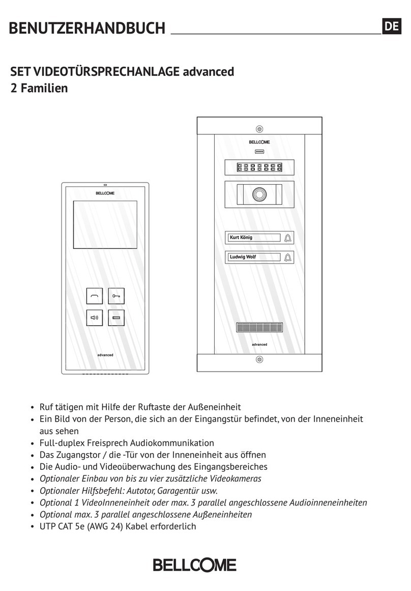
Bellcome advanced 2 families User manual
Bellcome
Bellcome Touch Line Smart+ Series User manual

Bellcome
Bellcome Touch Line Series User manual
Bellcome
Bellcome VPA.1FR02 User manual

Bellcome
Bellcome 2 smart User manual
