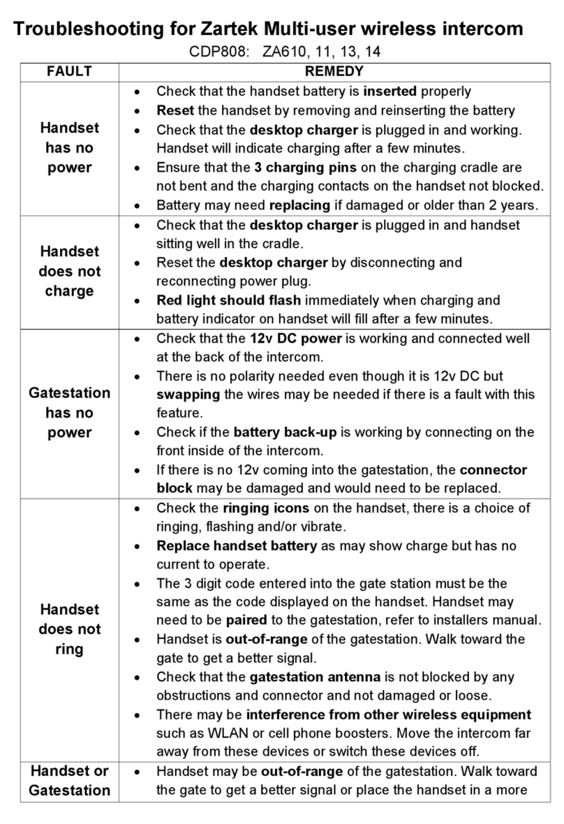
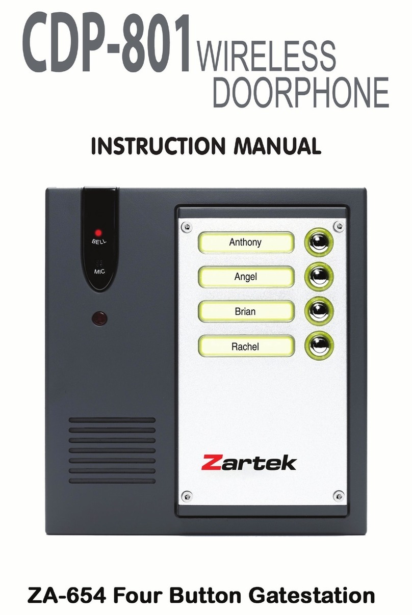
Zartek CDP-808 User manual

Zartek
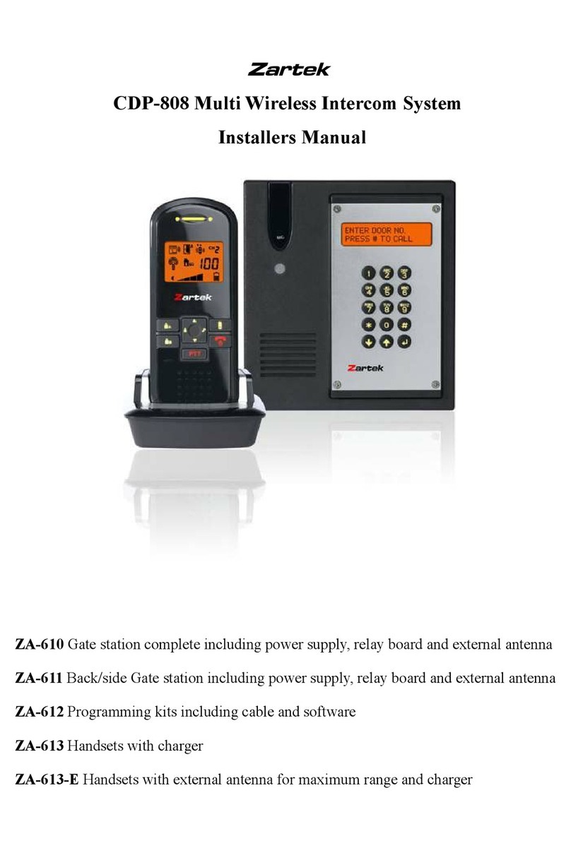
CDP-808 Multi Wireless Intercom System
Users Manual
ZA-610 Gate station complete including power supply, relay board and
external antenna
ZA-611 Back/side Gate station including power supply, relay board and
external antenna
ZA-612 Programming kits including cable and software
ZA-613 Handsets with charger
ZA-613- Handsets with external antenna for maximum range and charger

Overview:
The Zartek ireless Multi Intercom System is newly developed and three years of R&D in the making.
It is fully approved by ICASA. Applications for this system include housing complexes, apartments and
office blocks, large estates, long driveways etc.
This system can accommodate 80 separate channels. Communication is initiated from the gatestation
by selecting a 3 digit code such as 001 or 901 and pressing the # button. Only the selected houses
handset will ring and communication is established. Communication is simplex so only one person can
speak at a time but the gatestation’s microphone is always active so the visitor does not have to press
any key to speak. The inside handset can enter into the conversation at any time by pressing a PTT
button.
There are 2 triggers that can be activated from the handset for opening a motorized gate or striker lock.
Multiple handsets can be added for the same house to have internal communication. Range is terrain
dependant and is 100m in built-up areas and 350m in more open areas. The external antenna is
mounted as high as possible for improved coverage and audio.
Refer to this manual for in depth understanding of the operation on the gatestation and handset.
In short the visitor must press a 3 digit code corresponding to the houses handset. The handset will ring,
flash and or vibrate and the resident should then answer by pressing the PTT button. Now
communication is established. Visitors can speak when prompted to on the LCD screen and residents
can speak back by pressing the PTT button. A gate is opened by pressing the Door lock A or B button
and then the call can be ended. Handsets can be left on in the charger as there is smart charging.
Gate Station
The gatestation is used to call a particular house. Each house is given a code (000-999), there can be a
maximum of 100 separate codes/units per gatestation. The visitor enters a 3 digit code and presses the #
key to call a house. Even if the house number is 1 the visitor must enter a 3 digit code such as 001.
A countdown timer will start and the station will return to standby if there is no answer. If there is an
answer from a handset, a private communication channel is set-up. The communication is simplex,
meaning only one person can speak at a time. The visitor does not have to press any buttons as the
microphone is always active on the gatestation once the call is active. There are prompts on the screen
when to listen and when to speak. Sensitivity of the gatestation microphone is very high so the visitor
can speak from 1m from the gatestation and does not need to exit the car.
During a call, the handset can enter into the conversation by pressing a PTT (push to talk) button. There
are 2 gates that can be triggered from the handset and the screen will show which gate (A or B) has been
opened.
There is a search function on the gatestation in case the visitor does not know the house number. The
screen indicates how to search, Press **# to enter search mode and use the arrows to find the name and
house number. Once the number is located, press the 3 digit code and # to call. A door entry code can be
used to trigger the gate directly from the gate station.

A motion sensor will detect visitors coming within 3m of the gatestation and the screen and keypad will
light-up and be active. There is a back-up battery fitted into the gatestation which will power the unit for
4 hours in case of a power outage.
The installer will be equipped with the programming cable or pin codes to program the gatestation. Any
changes to displayed names, house numbers or additional handsets can be made via gatestation
programming.
Outline of call procedure:
Visitor presses 3 digit code and # key on gatestation to call
Handset rings and resident answers by pressing PTT
Visitor speaks when prompted
Resident presses PTT to speak or Lock A or B to trigger gate
Resident ends call
Operation
1) Under standby mode, the LCD will show following :
FOR MULTIPLE USER MODE
“ENTER 3 DIGIT No.
PRESS # TO CALL”
and
“ TO SEARCH FOR NAME
PRESS **# “
FOR SINGLE USER MODE (with one Programmed Residence Name)
“ PRESS # TO CALL”
2) To call a house or specific handset
MULTIPLE USER
Press the concerned house 3 digit number , then press #.
SINGLE USER
Just press #.
Note : A beep sound will be heard for each valid entry on keypad.
UP key
LCD
screscre
“#”key
ENTER key
DOWN key
Alphanumeric keys
“*”key

3) The LCD will show “ CALLIG “ and beep sound will be heard. At the same time, countdown
of 20 sec (20, 19, 18….) will be seen on the LCD and in case no reply from the handset after 20
sec, the calling process will stop and the visitor can repeat step 2 to call again.
The LCD will show “ NO REPLY PLS TRY AGAIN “
4) Once the handset replies by pressing the PTT button, the LCD will show “ CONNECTED “ and
the visitor can hear voice of the resident. Screen will display “ LISTEN NO ”
5) The visitor should speak only after he hears the two beeps and when the LCD show
“CONNECTED otherwise some words will be missed by the resident. Screen will display
“SPEAK NO “
6) The handset can reply at any time by pressing and holding the PTT button and speaking into
the microphone, the LCD will show “ CONNECTED “ and the visitor can hear voice of the
resident. Screen will display “ LISTEN NO ”. Note that the PTT (Push-To-Talk)button should
be pressed properly in before beginning to speak.
7) henever the LOCK A button K4 on handset is pressed, the door lock will be triggered and
LCD show “ DOOR A OPENED ”.
8) henever the LOCK B button K5 on handset is pressed, the dry contact will be closed
momentarily and LCD show “ DOOR B OPENED “.
9) hen the HAG UP button K2 on handset is pressed, the communication between gate station
and handset will stop and the unit will return to standby mode. In case the unit cannot receives
hang up signal from handset (either due to interference from other device or the resident forgets
to hang up), it will automatically hang up and return to standby mode 60 sec after no signal has
been received from handset.
10) To search for names and house no. of residents, press **#. The LCD will show the residents’
name and associated house no. in alphabetical order. Press UP/DO N key to turn page. Once
you located the name, press the associated house no. and then #.
11) Resident door entry code.
The residents can open the DOOR LOCK A by pressing * followed by the programmed 4 digit
secret door entry code. The LCD will show “ DOOR ENTRY CODE “ and the gate will open.
12) Infrared detector
henever the infrared detector detects movement ( 1- 3 m with people approaching towards
unit or 2- 5m with people walking across unit), the LCD and keypad will be active and light up.
If there is no further movement it will turn off after 15 seconds.
Back gatestation
It is possible to add an additional gatestation to be used on another or the same entrance, for instance to
be notified when visitors want to exit. The functions of the back gatestation are similar to the front
station as all the same names and codes are stored on the station. Gate triggering is limited in that a call
has to be initiated from the back gatestation in order to be able to trigger the gate it is connected to. A
system busy function can also be added to the back gatestation with a hard wire connection between
gatestations. This is used so that the visitor can be notified if the system is busy with another call and
they must wait.
Handset

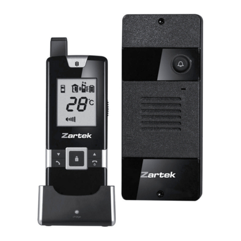
The handset is portable and rechargeable giving you the convenience of answering the gate from
anywhere in the house, garden and pool. A large LCD screen indicates house number, ring type,
incoming or outgoing calls, door opening etc. Each handset includes a mains adaptor, charging cradle
and rechargeable battery.
Communication is very clear and working range is typically 350m in built-up areas and 800m line-of-
sight. Operation of the handset is essentially like a two-way radio as all communication is done via a
PTT button. Handsets are able to receive communication from the gatestation once a call is active and
respond by pressing the PTT button.
A call can be made to the gatestation at any time even when the system is idle. This feature is used to
contact a guard by the gate.
Handsets are also able to communicate with other handsets in the same house if they all share the same
code. As many handsets can be added and all will ring when a call is made from the gate. There are 2
gate release buttons on the handset to trigger separate gates.
Each handset is given a unique 3 digit code when it is programmed to the gatestation. This code is the
handsets number or house’s unit number. Different coded handsets cannot speak to each other.
Installation of battery and charger
The handset is equipped with a removable rechargeable battery pack. Unscrew battery cover and place
battery as described on the battery. Plug the mains adaptor into the wall socket and connect the other
end to the desktop charging cradle. There is an indicator light on the desktop charger which flashes
when charging and remains on when full. Charging time is approximately 4 hours and the handset can
be always placed in the charger to keep it powered up always with a trickle charge. A battery level
indicator on the screen will show the battery level and charging status. Once the handset is removed
from the charger, the battery life is approximately 5 hours with average use.
Function of buttons (please refer to Figure above)
K6
Call aler selec bu on
K4
Lock A bu on
K
5
Lock B bu on
K3
Call
reply/
Calling ga e s a ion bu on
K9
Volume down bu on
K2
Hang Up/Power ON/OFF bu on
K1
Handse calling bu on
K8
Ringing one ime selec bu on
K7
Volume up bu on
Doorbell visual ligh
Microphone
Speaker

1. Handset calling button K1
To call another handset paired with the same house no., press K1, three beep sound will be
heard. Speak only after these three beep sound, release K1 when finish talking to hear reply from
opposite party. This is a push-to-talk button so the button must remain pressed in whilst you
speak directly into the microphone.
2. Hang up/Power ON/OFF button K2
This button has two functions :
a) Hang up after communicating with gate station. Both handset and gate station will return back to
standby mode.
b) Power ON/OFF – Long press of K2 for 4 seconds will switch on or off the handset.
3. Call reply/Calling gate station button/PTT K3
hen receiving a call from gate station, press K3 to start communicating with visitor. Each time
K3 is pressed, a two beep sound will be heard. Speak only after these two beep sound or the
visitor will miss out some words.
Under standby mode, press K3 can directly speak to the gate station. However, the gate station
cannot talk back. This is a push-to-talk button so the button must remain pressed in whilst you
speak directly into the microphone.
4. Lock A button K4
During communication with gate station, pressing K4 can activate relay A (with 1amp rating)
and cause the gate to open. The LCD will show door open icon with letter A for 5 sec once the
gate station successfully receives this command signal.
Under standby mode, pressing K4 can also trigger relay A and cause gate to open. Keep the
button pressed in for 3 seconds to trigger. This long press is a precaution against accidental
triggering.
5. Lock B button K5
During communication with gate station, pressing K5 can activate dry contact B (with 300mA
rating) to close momentarily for 3 sec. The LCD will show door open icon with letter B for 5 sec
once the gate station successfully receives this command signal.
Under standby mode, pressing K5 can also activate dry contact B. Keep the button pressed in for
3 seconds to trigger. This long press is a precaution against accidental triggering.
6: Call alert/ring type select button K6
Press K6 to select the preferred type of call alert from below :
a) Vibration only
b) Visual light only
c) Ringing tone only
d) Vibration + Visual light
e) Visual light + Ringing tone

f) Vibration + Ringing tone
g) Vibration + Visual light + Ringing tone
7:Volume Up K7 and Volume down K9
Press K7 and K9 to select your preferred volume. The ringing tone volume will also be adjusted
accordingly.
8: Ringing tone time select button K8
Press K8 to select the time of ringing tone when the handset is being called. Selecting 10 seconds
means you will hear 4 times of DING DONG. Selecting 15 sec means 6 times and selecting 20
sec means 8 times.
In case there is more than one handset paired with the same house no., this ringing tone time
must be set same for all handsets or it will follow the longest time.
9: Trigger Lock Disable Function K1 K6
Press K1 while holding down K6, the lock icon will show up, the keys K4 and K5 will be
locked and non functioning (i.e you will be unable to open the door lock A and B). Press again
K1 while holding down K6 will activate K4 and K5 again, the lock icon will go off.
Operation
1. hen the gate station calls to a particular handset (or house no.), the concerned handset
will show the call alert sign as selected by K6 and the gate station calling icon (X15) starts
flashing in the LCD.

2. The resident can reply the call by pressing PTT K3. Now handset signal icon will stay on
and the transmit icon (lightning) shows up every time K3 is pressed. Speak only after the
two beeps sound or otherwise the visitor will loose some of your words. Release K3 after
finish speaking and the unit enters reception mode with the transmit icon going off and
receive icon showing up in LCD. The resident can speak to the visitor anytime they prefer
by pressing K3.
3. In case the handset does not reply the call within the time period as set by the ringing tone
time (10 sec or 15 sec or 20 sec), both handset and gate station will return back to standby
mode automatically.
4. For house no. paired with more than one handset, whenever the gate station calls, all
handsets will start to show call alert sign. Only one handset can answer the call, the
remaining handsets will enter Tx inhibit mode so as not to interfere with the
communication.
5. To activate relay A or dry contact B, press K4 or K5 respectively. The gate open icon X18
will show up momentarily in LCD together with the respective letter A or B once the gate
station receives such command successfully.
6. Upon finishing communication, the resident can hang up by momentarily pressing K2.
Both handset and gate station will return to standby mode. In case the resident forgets to
hang up, the handset will hang up by itself approximately 1 minute after no activity has
been detected on any button.
7. During a call, all other handsets in the system (programmed with different house no.) will
enter Tx inhibit mode so as to avoid interference to the call under progress.
8. Under standby mode, the handset can speak to the gate station by pressing PTT K3, but the
gate station cannot talk back. The handset can also activate relay A or dry contact B by long
press of K4 or K5.
9. If there are more than one handset programmed with same house no., the handset can call
each other by pressing K1.
10. The battery can be charged up by placing handset in the supplied charger stand. During
charging, the red LED on the charger stand starts flashing and turns steady green once the
battery is fully charged up.
11. Beep sound will be heard for each valid entry of button.
Other manuals for CDP-808
2
Table of contents
Other Zartek Intercom System manuals
Popular Intercom System manuals by other brands

Glensound
Glensound BEATRICE M1 Product details

RTS
RTS Cronus user manual

Panasonic
Panasonic VL-GM201A Installation and operation guide

GVI Security
GVI Security GV-VP410Y Installation and operation manual

L-TEK
L-TEK TAB1 Planning documentation

NuTone
NuTone IM-3003 Series Homeowner's operating instructions