Bellcome Touch Line Smart+ Series User manual

DE
4 Drähte/4 Wires/4 Hilos/4 Fils/4 Fili/4 Przewody
EN
ES
FR
IT
PL
1/2/3 Familien
Video Türsprechanlagen KIT 3,5”/7”
Benutzerhandbuch
1/2/3 Families
VIDEO DOOR PHONE KIT 3.5”/7”
User manual
1/2/3 Familles
KIT VIDÉO INTERPHONE 3.5”/7”
Manuel de l'utilisateur
1/2/3 Famiglie
KIT VIDEO CITOFONO 3.5"/7"
Manuale dell’utente
1/2/3 Familias
KIT VÍDEO PORTERO 3.5"/7"
Manual del usuario
1/2/3 Rodziny
ZESTAW VIDEO INTERFON 3.5"/7"
Podręcznik użytkownika

KIT-INSTALLATION. Befolgen Sie die nachstehenden Schritte in der beschriebenen Reihenfolge.
SCHRITT 1. Lesen Sie die Diagramme in dieser Broschüre und die technischen Handbücher des KIT (VPA, VTx, SCU).
SCHRITT 2. Stellen Sie die elektrischen Verbindungen zu den Inneneinheiten (ATM, VTM, VTA) und dann zur VPA
-Außeneinheit her.
SCHRITT 3. Die elektrischen Anschlüsse der LCK-Türschloss und LOCK SUPPLY Türschlossversorgung an der SCU-
Stromversorgungseinheit und ggf. an den Anschlüssen an die EXIT-Taste anschließen; AUX zusätzliche
Installationen; BAT; Vcam analoge Videokamera.
SCHRITT 4. AUTORISIERTES PERSONAL !!! LESEN SIE DIE SICHERHEITSHINWEISE AUS DEM HANDBUCH DER
SCU-STROMVERSORGUNGSEINHEIT !!! TRENNEN Sie die Sicherungen und schließen Sie die L, N, an die
SCU an VERBINDEN Sie die Sicherungen mit dem Stromnetz. Die , S2-LEDs leuchten auf und S1 schaltet sich nur
ein, wenn die Batterie (12V / max. 42Ah) angeschlossen ist.
SCHRITT 5.1. PROGRAMMIERUNG DER HAUPTAUßENEINHEIT: RFID-KARTEN / TAGs Drücken Sie an der
SCU lange (3 Sek.) Die Taste PROG (Punkt 6). Die rote PROG-LED leuchtet Gehen Sie vom Haupteingang zum
VPA-Bedienfeld und berühren Sie jede RFID-KARTE eine Sekunde lang im Bereich (RFID). Für jede programmierte
RFID CARD / TAG gibt die Außeneinheit zwei Pieptöne aus. Befolgen Sie die gleichen Schritte, um alle RFID-Karten / TAGs
für alle Bewohner des Gebäudes zu programmieren. Kehren Sie zur SCU zurück und drücken Sie kurz die PROG-Taste.
Die rote LED erlischt. Das Hauptbedienfeld enthält die Adresse 1, die werkseitig eingestellt und betriebsbereit ist.
SCHRITT 5.2. PROGRAMMIERUNG DER ZUSÄTZLICHEN AUßENEINHEIT: NEUE ADREßE und RFID-KARTEN / TAGs. Wenn der
Zugang im Gebäude über zwei Eingänge erfolgt, muss das zusätzliche Feld VPA2 (Punkt 11) von Eingang 2 mit Adresse 2
eingerichtet werden. Drücken Sie bei SCU 2 lange die Taste PROG. Die rote PROG-LED leuchtet auf. Berühren Sie im
VPA2 -Bedienfeld die Fam.1-Taste Piep und berühren Sie zweimal kurz die Fam.1-Taste. Die Außeneinheit(langer ton)
bestätigt die Speicherung der Adresse 2 mit zwei kurzen Signaltönen. Fahren Sie mit der Programmierung der CARDS / TAGs im
VPA2-Bedienfeld fort. Jede Berührung der CARD / TAG im Bereich wird vom VPA2 mit zwei Signaltönen bestätigt.
Kehren Sie zur SCU2 zurück und drücken Sie kurz die PROG-Taste. Die rote LED erlischt. Die VPA2- und VPA1-Außeneinheit
sind funktionsbereit, mit allen Inneneinheiten im Gebäude.
SCHRITT 6.1 PROGRAMMIERUNG DER ADRESSE DES FAM.1-INNENEINHEIT. Die Inneneinheit behalten die Adresse 1,
die vom Hersteller eingestellt ist.
SCHRITT 6.2 PROGRAMMIERUNG DER ADRESSE DER Fam.2, Fam.3 oder mehr INNENEINHEITEN. Die Inneneinheiten für
Familie 2 haben Adresse 2, die Inneneinheiten für Familie 3 haben Adresse 3 und so weiter für 4, 5 usw.
Programmieren Sie die neuen Adressen wie folgt: Drücken Sie bei SCU 1 lange (3 Sek.) Die Taste PROG. Die rote
PROG-LED leuchtet Drücken Sie an den Anschlüssen für Familie 2 die Taste . Die Inneneinheit bestätigt mit einem
langen Piepton. Drücken Sie zweimal kurz auf die Symboltaste. Zwei kurze Pieptöne werden ausgegeben. Die Inneneinheit
speichert die Adresse 2. Fahren Sie mit der Programmierung der Adresse 3 bei Familie 3 fort, indem Sie die gleichen Schritte
ausführen. Drücken Sie lange auf die Taste und drücken Sie nach dem langen Signalton die Taste dreimal kurz.
Kehren Sie zur SCU zurück und drücken Sie kurz die PROG-Taste. Die Speicherung wird durch drei kurze Pieptöne bestätigt.
Die rote LED erlischt.Die Inneneinheiten sind betriebsbereit.
EMPFOHLENE VERKABELUNG (Punkt 1) Behalten Sie die gleichen Drahtfarben für die gleichen Verbindungen bei.
2
Aus Gründen der elektrischen Sicherheit empfehlen wir die Installation eines Erdungskabels (mindestens 1,00 mm - Grün / Gelb)
vom -Feld (VPM) zur Stromversorgungseinheit (SCU).
1
DETAILLIERTE PRODUKTCODES
VPA - advanced Video-Außeneinheit; Produktcodes: 1Fam.VPA.1S (F)R02.xxy04; 2Fam.VPA.2S (F) R02.xxy04;
3Fam.VPA.3S (F) R02.xxy04; 5Fam.VPA.5S (F) R02.xxy04 (S = Aufputzmontage, F = Unterputzmontage, R = RFID CARD
/ TAG Zugang)
RFID-Zugang CARD / TAG (gesichert beim Lesen und Kopieren). Sie werden gespeichert und können aus der VPM gelöscht
werden.
ATM - smart+ Audio-Inneneinheit; Produktcode: ATM.0S402.xxy04
VTM - smart+ 3.5 "Video-Inneneinheit; Produktcode: VTM.3S402.xxy04
VTM / VTA - smart+ / advanced 7 "Video-Inneneinheit; Produktcodes: VTM.7S402.xxy04 / VTA.7S902.xxy04
VCB - Videoverbindungsbox (1 Videoeingang / 4 Videoausgänge-4 Fam.); Produktcode: VCB
DE
INSTALLATIONSANLEITUNG - VIDEO TÜRSPRECHANLAGEN KIT
Vielen Dank, dass Sie sich für die BELLCOME Produkte entschieden haben. Wir begleiten Sie während der gesamten
Garantiezeit. Für technische Unterstützung und weitere Fragen können Sie uns unter: ELECTRA Building Communications GmbH
+43 1 810 20 99, [email protected]om kontaktieren.
2
1) Max. 75 lm 4 x 0.5 mm (H03VV-F4G 0.5)
2
2) Max. 150 lm 4 x 0.75 mm (H05VV-F4G 0.75) 3) Max. 250 lm UTP cat5e (AWG24) oder UTP cat6e (AWG23)

DE
VSB - Videoselektorbox; Produktcode: VSB.4DN02.xxy04 (4 Videoeingänge / 1 Videoausgang)
SCU - Stromversorgungseinheit für 1 Fam; Produktcode: SCU.VDR02.xxy14 (110-230 Va.c., 50 Hz / 13,5 Vd.c.-2 Ad.c.).
Stromversorgungseinheit für 3 Fam; Produktcode: SCU.VDR02.xxy34 (110-230 Va.c., 50 Hz / 13,5 Vd.c.-2 Ad.c.)
PSU - Zusätzliche Versorgungseinheit; Produktcode: PSU.VDR02.xxy04 (110-230 Va.c., 50 Hz / 13,5 Vd.c.-2 Ad.c.), erforderlich,
wenn aus verschiedenen Gründen die Versorgungsspannung (+ U, GND) an den Hubs der Inneneinheit unter 12 V fällt.
Vcam - Zusätzliche Videokamera-Verbindung, analog 1Vv-v, PAL
LCK/LCK - Anschluss eines Wechselstromschloss (max.5Aa.c./ 24Va.c), eines Gleichstromschloss (max.3Ad.c./24Vd.c.) oder
eines elektromagnetische Gleichstromschloss (max.3Ad.c./24Vd.c.)
LOCK SUPPLY - Anschluss der Türschlossversorgung (max. 24 Va.c./24Vd.c.). Eines Gleichstromschloss von max.
0.6Ad.c./12Vd.c. kann direkt von der SCU mit Strom versorgt werden, indem Sie die Verbindungen an den +U - GND
- Anschlüssen des VIDEO DOOR PANEL - Verbinder hergestellt werden.
NO/NC – Einstellung der Türschloss Funktionsmodus. NO-Normal Open - LCK-Relais normal offen; NC-Normal Closed -
LCK-Relais normal geschlossen.
EXIT/EXIT - Anschluss der EXIT-Taste (im Gebäude eingebaut)
AUX1 / AUX2 - Anschluss von zusätzlichen Installationen - Eingangstor, Garagentor, Außenbeleuchtung usw. (Punkt 4)
+ BAT / - BAT - Anschluss der wiederaufladbaren Batterie
DBL1 / DBL2 - Verbindung der Eingangstürklingel (Wohnungstürklingel)
GONG1 / GONG2 - Verbindung der Distanzruftürklingel (GONG)
PARALLELE VERBINDUNG VON ZWEI AUSSENBEREICHE (Siehe Diagramm von Punkt 11)
Wenn das Gebäude über mehrere Eingänge verfügt, können Sie VPA-Außeneinheit mit einer eigenen SCU-
Stromversorgungseinheit installieren, die über ein eigenes Gate verfügt. Die Haupt-Außeneinheit VPA1 behält die vom
Hersteller eingestellte Adresse 1 und nur die RFID-Zutrittskarten / Tags werden am VPA1 programmiert (siehe Schritt 5.1).
Die VPA2-Zusatz-Außeneinheit ist mit Adresse 2 und mit den RFID-Zutrittskarten / Tags programmiert (siehe Schritt 5.2).
PARALLELE VERBINDUNG DER ZUSÄTZLICHEN INNENEINHEITEN (Siehe Diagramm von Punkt 10)
In der Wohngebäude können TL zusätzliche Inneneinheiten (ATM / VTM 3.5" / VTM 7 "/ VTA 7") mit demselben Kabeltyp
für dieselben Verbindungen (+ U, C / D, GND, Vin / Vout) installiert werden. Alle Inneneinheiten in einem Apartment
haben die Adresse der HauptInneneinheit. Für Fam.1 haben die Inneneinheiten die vom Hersteller festgelegte
Adresse 1. Für Fam. 2, 3 (Fam. 4, 5 oder mehr) programmieren Sie die Inneneinheiten mit den Adressen 2, 3
(oder 4, 5 usw.). Siehe Schritt 6.2.
2
B.
1. Normalbetriebsmodus, ohne BAT: Die Netzwerk und + U-LEDs sind grün. Die PROG - und BAT - LEDs sind ausgeschaltet.
2. Normaler Betriebsmodus, bei angeschlossenem BAT: Die LEDs Network , BAT und + U sind grün.
3. Das System funktioniert nur im Akkubetrieb (die Installation funktioniert bis zur vollständigen Entladung des Akkus):
Die LED BAT leuchtet grün, die LEDs und + U sind ausgeschaltet. Überprüfen Sie die Sicherungen an der SCU (FUSE T-1, 6A)
und 2x6A vom Netzwerk .
4. Das System funktioniert mit einer defekten Batterie. Die Netzwerk , + U-LEDs sind grün, die BAT-LED ist ausgeschaltet.
Wechseln Sie die Batterie!
5. Die Außeneinheit funktioniert nicht (die rote LED der Außeneinheit blinkt nicht, die Ruftasten sind nicht beleuchtet):
Die LEDs , BAT und + U sind grün. Auf der SCU ist die LED VIDEO AUßENEINHEIT rot. Überprüfen Sie die Kontinuität und die
Genauigkeit der + U- und GND-Verbindungen von der SCU zum Paneel.
6. Eine Inneneinheit funktioniert nicht (die Tasten sind nicht beleuchtet, wenn kein Bild und Ton anwesend sind): Die LEDs ,
BAT und + U sind grün. Eine der LEDs OUT1, OUT2 oder OUT3 ist rot. Überprüfen Sie die Kontinuität und Genauigkeit der
+ U- oder GND-Verbindungen von der SCU zur Inneneinheit.
7. Des Schloss funktioniert nicht (LCK, LCK): Überprüfen Sie die Genauigkeit der Verbindungen von der SCU zum Schloss.
8. Die Anzeige der Inneneinheiten ist blau (während des Anrufs ist das Inneneinheit blau, es gibt Ton): Überprüfen Sie die Kontinuität
und Genauigkeit der Vin-, Vout- und GND-Verbindungen von der Außeneinheit zur Videoinneneinheit während des Anrufs.
9. Die Inneneinheiten werden nicht gerufen, die PROG-LED ist rot: Überprüfen Sie die Kontinuität und die Genauigkeit der C/D-,
+ U - und GND-Verbindungen von der Außeneinheit zur Video-Inneneinheit.
10. Die Inneneinheit für Familie 2, Familie 3 oder höhere Adressen kann nicht angerufen werden: die Inneneinheit mit der richtigen
Adresse (Wohnungsnummer) im Benutzerhandbuch neu programmieren.
FEHLERSUCHE UND SERVICE FÜR DIE VIDEO-TÜRSPRECHANLAGE

KIT INSTALLATION. Follow the steps below, in the described order.
STEP 1. Read the diagrams in this brochure and the technical manuals of the KIT (VPA, VTx, SCU).
STEP 2. Make the electrical connections to the terminals (ATM, VTM, VTA) and then to the VPA outdoor panel.
STEP 3. Make the electrical connections of the LCK door lock and LOCK SUPPLY to the terminals of the SCU central unit
and, if necessary, the connections to: the EXIT button; AUX additional installations; BAT; Vcam analog video camera.
STEP 4. AUTHORIZED PERSONNEL!!! READ THE SAFETY INSTRUCTIONS FROM THE MANUAL OF THE SCU CENTRAL
SUPPLY UNIT!!! DISCONNECT the fuses and make the L,N, connections to the SCU CONNECT the fuses to the
power network. The , S2 LEDs turn on, and S1 turns on only if the battery (12V/max. 42Ah) is connected.
STEP 5.1. PROGRAMMING THE MAIN ENTRANCE PANEL: RFID CARDS/TAGs At the SCU, long press (3 sec.) the PROG
button (point 6). The PROG Red LED turns on Go to the VPA panel from the main entrance and touch each RFID CARD
to the (RFID) area for one second. For each programmed RFID CARD/TAG, the panel issues two beeps.
Follow the same steps for programming all the RFID CARDS/TAGs, for all the residents of the building.
Return to the SCU and short press the PROG button. The Red LED turns off. The main panel keeps address 1, which
is set from the factory and is ready to function.
STEP 5.2. PROGRAMMING THE ADDITIONAL PANEL: NEW ADDRESS and RFID CARDS/TAGs. If the access in the building
is made through two entrances, the VPA2 additional panel (point 11) from entrance 2 must be set up with address 2.
At SCU 2 long press the PROG button. The PROG Red LED turns on. At the VPA2 panel, long touch the Fam.1 key
(long confirmation beep), then short touch the Fam.1 key, twice. The panel confirms the storage of address 2 with
two short beeps. Continue programming the CARDS/TAGs in the VPA2 panel. Each touch of the CARD/TAG to the area is
confirmed by the VPA2 with two beeps. Return to the SCU2 and short press the PROG button. The Red LED turns off.
The VPA2 and VPA1 panels are ready to function, with all the terminals in the building.
STEP 6.1 PROGRAMMING THE ADDRESS OF THE Fam.1 TERMINAL. The terminals keep Address 1, which is set by the
manufacturer.
STEP 6.2 PROGRAMMING THE ADDRESS OF THE Fam.2, Fam.3 or more TERMINALS. The terminals for Family 2 will have
address 2, the terminals for Family 3 will have address 3 and so on for 4, 5 etc.
Program the new addresses as follows: At SCU 1 long press (3 sec.) the PROG button. The PROG Red LED turns on
At the terminals for Family 2, long touch the key. The terminal confirms with one long beep. Short touch the
key twice. Two short beeps are issued. The terminal stores address 2. Continue programming address 3 at Family 3 following
the same steps. Long touch the key and after the long beep, short touch the key three times. Storage is confirmed
with three short beeps. Return to the SCU and short press the PROG button. The Red LED turns off. The terminals are
ready to function.
RECOMMENDED CABLES (point 1) Maintain the same wire colors for the same connections.
2
Out of electrical safety reasons, we recommend installing a grounding cable (minimum 1.00 mm – Green/Yellow) from the
panel (VPM) to the central unit (SCU).
1
DETAILED PRODUCT CODES
VPA - advanced video outdoor panel; Product codes: 1Fam.VPA.1S(F)R02.xxy04; 2Fam.VPA.2S(F)R02.xxy04;
3Fam.VPA.3S(F)R02.xxy04; 5Fam.VPA.5S(F)R02.xxy04 (S= Surface mounting, F= Flush mounting, R= RFID CARD/TAG access)
RFID access CARD/TAG (secured at reading and copying). They are stored and can be deleted from the VPM.
ATM - smart+ audio terminal; Product code: ATM.0S402.xxy04
VTM - smart+ 3.5” video terminal; Product code: VTM.3S402.xxy04
VTM/VTA - smart+/advanced 7” video terminal; Product codes: VTM.7S402.xxy04/ VTA.7S902.xxy04
VCB – Video connection box (1 video input/4 video outputs - 4 Fam.); Product code: VCB.4DN02.xxy04
EN
INSTALLATION INSTRUCTIONS – VIDEO DOOR PHONE KIT
Thank you for choosing the BELLCOME products. We will assist you throughout the entire warranty period.
For technical support and assistance you can contact us at ELECTRA Building Communications GmbH +43 1 810 20 99,
2
1) Max. 75 ml 4 x 0.5 mm (H03VV-F4G 0.5)
2
2) Max. 150 ml 4 x 0.75 mm (H05VV-F4G 0.75)
3) Max. 250 ml UTP cat5e (AWG24) or UTP cat6e (AWG23)

EN
VSB – Video selection box; Product code: VSB.4DN02.xxy04 (4 video inputs/1 video output)
SCU – Central supply unit for 1 Fam; Product code: SCU.VDR02.xxy14 (110-230 Va.c., 50 Hz / 13,5 Vd.c.-2 Ad.c.).
Central supply unit for 3 Fam; Product code: SCU.VDR02.xxy34 (110-230 Va.c., 50 Hz / 13,5 Vd.c.-2 Ad.c.).
PSU – Additional supply unit; Product code: PSU.VDR02.xxy04 (110-230 Va.c., 50 Hz / 13,5 Vd.c.-2 Ad.c.), necessary when,
due to various reasons, the supply voltage (+U, GND) at the hubs of the terminals drops below 12V.
Vcam – Additional video camera connection, analogic 1Vv-v, PAL
LCK/LCK – Connection of an alternating current lock (max.5Aa.c./24Va.c.), a direct current lock (max.3Ad.c./24Vd.c.) or an
electromagnetic lock (max.3Ad.c./ 24Vd.c.)
LOCK SUPPLY – Connection of the door lock supply (max. 24 Va.c./24Vd.c.). A direct current lock of max. 0.6Ad.c./12Vd.c. can
be powered directly from the SCU by making the connections at the +U - GND connections of the VIDEO DOOR PANEL
connector.
NO/NC – Setting of the door lock functioning. NO-Normal Open - LCK relay normal open; NC-Normal Closed - LCK relay
normal closed.
EXIT/EXIT – Connection of EXIT button (mounted inside the building)
AUX1/AUX2 – Connection of additional installations – auto gate, garage door, outdoor lighting etc. (point 4)
+ BAT/- BAT – Connection of rechargeable battery
DBL1/DBL2 – Connection of entrance doorbell (apartment doorbell)
GONG1/GONG2 – Connection of distance call doorbell (GONG)
TROUBLESHOOTING AND SERVICE FOR THE VIDEO DOOR PHONE SYSTEM
PARALLEL CONNECTION OF TWO OUTDOOR PANELS (See the diagram from point 11)
If the building has multiple entrances, you can install VPA outdoor panels with their own SCU central supply unit, which will
command its own gate. The VPA1 main outdoor panel keeps address 1, set by the manufacturer and only the RFID access
cards/tags will be programmed at the VPA1 (see Step 5.1). The VPA2 additional panel is programmed with address 2 and
with the RFID access cards/tags (see Step 5.2).
PARALLEL CONNECTION OF THE ADDITIONAL TERMINALS (See the diagram from point 10)
Inside the residence you can install TL additional terminals (ATM/VTM 3.5”/ VTM 7”/ VTA 7”) using the same type
of cable, for the same connections (+U, C/D, GND, Vin/Vout). All the terminals in one apartment will have the
address of the main terminal. For Fam.1 the terminals have address 1 set by the producer. For Fam. 2, 3
(Fam. 4, 5 or more), program the terminals with addresses 2, 3 (or 4, 5 etc.). See Step 6.2.
2
B.
1. Normal functioning mode, without BAT: the and +U LEDs are green. The PROG and BAT LEDs are turned off.
2. Normal functioning mode, with BAT connected: the , BAT and +U LEDs are green.
3. The system functions only on battery (the installation functions correctly until the full discharge of the battery): the
BAT LED is green, the and +U LEDs are turned off. Check the fuses on the SCU (FUSE T-1, 6A) and 2x6A from the network .
4. The system functions with a broken battery. The , +U LEDs are green, the BAT LED is turned off. Change the battery!
5. The outdoor panel does not function (the red LED from the outdoor panel does not blink, the call keys are not backlighted):
The , BAT and +U LEDs are green. At the SCU, the VIDEO DOOR PANEL LED is red. Check the continuity and the accuracy of
the +U and GND connections from the SCU to the panel.
6. A terminal does not function (the keys are not backlighted when touched, there is no image and sound): the , BAT and
+U LEDs are green. One of the OUT1, OUT2 or OUT3 LEDs is red. Check the continuity and accuracy of the +U or GND
connections from the SCU to the terminal.
7. The lock does not function (LCK, LCK): check the accuracy of the connections from the SCU to the lock.
8. The display of the terminal is blue (during call, the terminal is blue, there is sound): check the continuity and accuracy of the
Vin, Vout and GND connections from the outdoor panel to the video terminal.
9. The terminals are not called, the PROG LED is red: check the continuity and the accuracy of the C/D, +U and GND
connections from the outdoor panel to the video terminal.
10. The terminal for Family 2, Family 3 or with higher addresses cannot be called (The Family 1 terminal is always called):
reprogram the terminal with the correct address (the number of the apartment) according to the procedure in the user manual
of the terminal.

LA INSTALACIÓN DEL KIT. Siga los pasos de abajo, en el orden descrito a continuación.
PASO 1. Lea los esquemas de este folleto y los libros técnicos del KIT (VPA, VTX, SCU).
PASO 2. Haga las conexiones eléctricas en los terminales (ATM, VTM, VTA) y luego al panel exterior VPA.
PASO 3. Haga las conexiones de la cerradura LCK y de la alimentación de la cerradura LOCK SUPPLY a las bornas de la unidad
central SCU y, en su caso, las conexiones para: botón EXIT; instalaciones auxiliares AUX; BAT; cámara vídeo analógica Vcam.
PASO 4. ¡¡¡PERSONAL AUTORIZADO!!! LEA LAS INSTRUCCIONES DE SEGURIDAD DEL MANUAL DE LA UNIDAD CENTRAL SCU!!!
DESACOPLE los fusibles y haga las conexiones L,N, a SCU ACOPLE los fusibles a la red. A SCU se encienden los
LEDs , S2, y S1 solamente si tiene conectada la batería (12V/max. 42Ah).
PASO 5.1. PROGRAMACIÓN PANEL ENTRADA PRINCIPAL: TARJETAS RFID A SCU apretar largamente (3 seg.) el botón
PROG (punto 6). El LED rojo PROG se enciende Vaya al panel VPA de la entrada principal y toque por un segundo
cada TARJETA RFID de la zona (RFID). Para cada TARJETA RFID programada,el panel emite dos beeps.
Continúe de este modo hasta que programe todas las TARJETAS RFID, para todos los habitantes del edificio Vuelva
a SCU y apriete cortamente el botón PROG. El LED rojo se apaga. El Panel principal queda con la dirección 1 ajustada
desde la fábrica y está listo para funcionar.
PASO 5.2. PROGRAMACIÓN PANEL ADICIONAL: LA NUEVA DIRECCIÓN y TARJETAS RFID. Si el acceso en el edificio se
hace por medio de dos entradas, el panel adicional VPA2 (punto 11) de la entrada 2 debe ser ajustado con la
dirección 2. A SCU 2 apriete largamente el botón PROG. El LED PROG rojo se enciende. Al panel VPA2 apriete largamente
la tecla Fam.1 (beep largo de confirmación), luego apriete cortamente dos veces la tecla Fam.1. El panel confirma con dos
beeps cortos la memorización de la dirección 2. Continúe con la programación de las TARJETAS en el panel VPA2
Cada toque de la TARJETA de la zona va a ser confirmado por VPA2 mediante dos beeps. Volver a SCU2 y apretar
cortamente el botón PROG. El LED rojo se apaga. El panel VPA2 y VPA1 están listos para funcionar, con todos los
terminales del edificio.
PASO 6.1 PROGRAMACIÓN DE LA DIRECCIÓN TERMINAL Familia 1. Los terminales quedan con la Dirección 1 ajustada por
el productor.
PASO 6.2 PROGRAMACIÓN DE LA DIRECCIÓN TERMINAL Familia 2, Familia 3 o más. Los terminales de la Familia 2 van a
tener la dirección 2, los terminales de la Familia 3 van a tener la dirección 3 y así sucesivamente hasta 4, 5 etc.
Programe las nuevas direcciones de la siguiente manera: En la SCU 1, mantenga presionado largamente (3 seg.)
el botón PROG. El LED rojo PROG se enciende En los Terminales de la Familia 2, mantenga presionada largamente la tecla
. El terminal confirma con un beep largo. Presione cortamente la tecla dos veces. Se escuchan dos beeps cortos.
El terminal ha memorizado la dirección 2. Continúe de la misma manera con la programación de la dirección 3 en la Familia 3.
Mantenga presionada largamente la tecla y después del beep largo, presione brevemente la tecla tres veces.
La memorización se confirma con tres beeps cortos. Volver a SCU y apretar cortamente el botón PROG.
El LED rojo se apaga. Los terminales están listos para funcionar.
CABLES RECOMANDADOS (punto 1) Mantenga los mismos colores de hilo para las mismas conexiones.
2
Por motivos de seguridad eléctrica, recomendamos instalar un cable de conexión a tierra (mínimo 1,00 mm - verde / amarillo)
desde el panel (VPA) al de la unidad central (SCU).
1
SIGNIFICADO DE LA CODIFICACIÓN DE LOS PRODUCTOS.
VPA- Panel exterior video smart; Código de productos: 1Fam.VPA.1S (F) R02.xxy04; 2Fam.VPA.2S (F) R02.xxy04;
3Fam.VPA.3S (F) R02.xxy04; 5Fam.VPA.5S (F) R02.xxy04 (S = Montaje en superficie, F = Montaje enterrado, R = Acceso a
TARJETA RFID)
TARJETA de acceso RFID (Seguro para lectura y copia). Se memorizan y se pueden borrar en APM o VPM.
ATM - Terminal audio smart+; Código de producto: ATM.0S402.xxy04
VTM – Terminal video 3.5 "smart+ Código de producto: VTM.3S402.xxy04,
VTM / VTA - Terminal video 7 "smart+ / advanced; Código de productos: VTM.7S402.xxy04 / VTA.7S902.xxy04
VCB - Dosis de derivación video (1 entrada video / 4 salidas de video-4 Fam); Código de producto: VCB.4DN02.xxy04
ES
INSTRUCCIONES PARA LA INSTALACIÓN - KIT VÍDEO INTERFONO
Estimado Cliente, gracias por haber elegido los productos BELLCOME. Nosotros vamos a estar junto a usted durante todo el
período de garantía. Para sporte técnico y asesoramiento nos puede contactar en ELECTRA Building Communications GmbH
+43 1 810 20 99, [email protected]om.
2
1) Max. 75 ml 4 x 0.5 mm (H03VV-F4G 0.5)
2
2) Max. 150 ml 4 x 0,75 mm (H05VV-F4G 0,75)
3) Max. 250 ml UTP cat5e (AWG24) o UTP cat6e (AWG23)

ES
DIAGNÓSTICO Y SERVICIO PARA LA INSTALACION DE VIDEO INTERFONO
ACOPLAMIENTO EN PARALELO DE DOS PANELES EXTERIORES (Ver Figura del punto 11)
Si el edificio tiene múltiples entradas, puede instalar paneles externos de tipo VPA con su propia unidad
central SCU en cada entrada que controlará su propia puerta. El panel externo principal VPA1 permanece con
la dirección 1 establecida por el productor, y el VPA1 solo programará TARJETAS de acceso RFID (ver Paso 5.1).
El panel adicional VPA2 está programado con la dirección 2 y las TARJETAS de acceso RFID (consulte Paso 5.2)
ACOPLAMIENTO EN PARALELO DE LOS TERMINALES ADICIONALES (Vea la Figura del punto 10)
Puede instalar dentro de la vivienda terminales adicionales TL (ATM / VTM 3.5 / VTM 7 "/ VTA 7")
utilizando el mismo tipo de cable para las mismas conexiones (+ U, C / D, GND, Vin / Vout). Todos los terminales en un
apartamento tendrán la dirección del terminal principal. Para Fam.1, los terminales tienen la dirección 1 establecida por el
fabricante. Para Fam. 2, 3 (Fam. 4, 5 o más), programe los terminales con las direcciones 2.3 (o 4.5, etc.). Ver Paso 6.2.
2
VSB - Dosis de selección de video; Código de producto: VSB.4DN02.xxy04 (4 entradas de video / 1 salida de video)
PSU - Fuente de alimentación suplementaria; Código de producto: PSU.VDR02.xxy04 (110-230 Vc.a., 50 Hz / 13,5 Vc.c.-2 Ac.c.)
necesaria cuando, por diversos motivos, la tensión de alimentación (+ U, GND) en las bornas de los terminales cae por debajo de 12V.
Vcam - Conexión de la cámara video adicional, analógica 1Vv-v, PAL
LCK/LCK – Conexión de una cerradura de corriente alterna (max.5Ac.a./24Vc.a.), de una cerradura de corriente continua
(max.3Ac.c./24Vc.c.) o un electroimán para bloquear la puerta (max.3Ac.c./ 24Vc.c.)
LOCK SUPPLY – Conexión de la alimentación de la cerradura (max. 24 Vc.a./24Vc.c.). Una cerradura de corriente continua de
máx. 0.6Ac.c. /12Vc.c. se puede alimentar directamente desde la SCU haciendo las conexiones en las bornas +U - GND
del conector VIDEO DOOR PANEL.
NO/NC – Modo de funcionamiento de la cerradura. NO-Normal Open - Relé LCK normal abierto; NC-Normal Closed - Relé LCK
normal cerrado.
EXIT / EXIT - Conexión del botón EXIT (montado dentro del edificio)
AUX1 / AUX2 - Conexión de instalaciones adicionales- puerta del automóvil, puerta de garaje, iluminación exterior, etc.
(punto 4)
+ BAT / - BAT - Conexión de la batería recargable
DBL1 / DBL2 - Conexión del timbre de entrada (timbre del apartamento)
GONG1 / GONG2 - Conexión del timbre de llamada a distancia (GONG)
SCU - Unidad central de alimentación para 1 Fam; Código de producto: SCU.VDR02.xxy14 (110-230 Vc.a., 50 Hz / 13,5 Vc.c.-2 Ac.c.).
Unidad central de alimentación para 3 Fam; Código de producto: SCU.VDR02.xxy34 (110-230 Vc.a., 50 Hz / 13,5 Vc.c.-2 Ac.c.)
B.
1. Estado de funcionamiento normal sin BAT: los LED de red y +U son de color verde. Los LED PROG y BAT están apagados.
2. Estado de funcionamiento normal con BAT conectada: los LED de red, BAT y +U están en verde.
3. La instalación funciona solamente en la batería (la instalación funciona correctamente hasta la apertura completa
de la batería): El LED BAT es verde, los LEDs y +U están apagados. Verifique los fusibles de SCU (FUSE T-1,6A) y
2x6A de la red .
4. La instalación funciona con la batería defectuosa. Los LED de red, +U están en verde, el LED de BAT está apagado.
¡Cambia la batería!
5. No funciona el panel exterior (el LED rojo del panel exterior no ilumina de manera intermitente, los teclados de apelación
no son iluminadas): los LEDs, BAT y +U son verdes. En SCU el LED de VIDEO DOOR PANEL es rojo. Verifique la continuidad
y la precisión de las conexiones +U y GND de SCU hacia el panel.
6. No funciona un terminal (los teclados no iluminan al apretar, no hay imagen y sonido): los LEDs , BAT y +U son verdes.
Uno de los LEDs OUT1, OUT2 o OUT3 es rojo. Verifica que la continuidad y la precisión de las conexiones +U o GND de SCU
hacia el terminal.
7. No funciona la cerradura de seguridad (LCK, LCK): verifique la precisión de las conexiones de SCU a la cerradura de seguridad.
8. La pantalla del terminal es azul (en la llamada, el terminal tiene el color azul, hay sonido): verifique la continuidad y la
precisión de las conexiones Vin, Vout, del panel exterior, la unidad central y el terminal video.
9. Los terminales no son llamados, el LED PROG es rojo: verifique la continuidad y la corrección de las conexiones C / D, +U y
GND desde el panel exterior al terminal de video.
10. El terminal de la Familia 2, Familia 3 o con direcciones mayores no puede ser llamado (Se llama siempre el terminal de la
Familia 1): reprograme el terminal con la dirección correcta (el número del apartamento) conforme al procedimiento del manual
de utilización del terminal.

L'INSTALLATION DU KIT. Suivez les pas ci-dessous, dans l'ordre descrite.
PAS 1. Lisez les schémas compris dans cette brochure et les livres techniques du Kit (VPA, VTX, SCU).
PAS 2. Faites les connexions électriques aux terminaux (ATM, VTM, VTA) et puis au panneau extérieur VPA
PAS 3. Faites les connexions électriques de la serrure LCK et de l'alimentation de la serrure LOCK SUPPLY aux bornes de
l`unité centrale SCU et, s'il est le cas, les connexions pour: le bouton EXIT; les installations auxiliaires AUX; BAT;
caméra vidéo analogique Vcam.
PAS 4. PERSONNEL AUTORISÉ!!! LISEZ LES INSTRUCTIONS DE SÉCURITÉ DU MANUEL DE L'UNITÉ CENTRALE SCU!!!
DÉCOUPLEZ les fusibles et faites les connexions L, N, à SCU COUPLEZ les fusibles au réseau. À SCU les LED
s'allument , S2, et S1 juste si la batterie est connectée (12V/max. 42Ah).
PAS 5.1. PROGRAMMATION DU PANNEAU ENTRÉE PRINCIPALE: CARTES RFID À SCU appuyez longuement (3 sec.) sur le
bouton PROG. (point 6). Le LED rouge PROG s'allume Allez au panneau VPA de l'entrée principale et faites le
contact pendant une seconde de chaque CARTE RFID avec la zone (RFID). Pour chaque CARTE RFID programmé,
le panneau émet deux bips. Continuez de cette manière jusqu'à ce que toutes les CARTES RFID seront programmées,
pour tous les locataires du bâtiment Retournez à SCU et appuyez brièvement sur le bouton PROG. Le LED rouge s'éteint.
Le panneau principal reste avec l'adresse 1 réglée dès la fabrication et est prête pour le fonctionnement.
PAS 5.2. PROGRAMMATION DU PANNEAU SUPPLÉMENTAIRE: LA NOUVELLE ADRESSE et les CARTES RFID. Si l'accès dans
le bâtiment est fait par deux entrées, le panneau supplémentaire VPA2 (point 11) de l'entrée 2 doit être réglé avec l'adresse 2.
À SCU 2 appuyez longuement sur le bouton PROG. Le LED PROG rouge s'allume. Au panneau VPA2 appuyez longuement sur
la touche Fam. 1 (bip long de confirmation), après appuyez brièvement deux fois la touche Fam. 1. Le panneau confirme avec
deux bips brefs le stockage de l'adresse 2. Continuez avec la programmation des cartes dans le panneau VPA2 Chaque
contact de la CARTE avec la zone sera confirmée par VPA2 par deux bips. Retournez à SCU2 et appuyez brièvement le
bouton PROG. Le LED rouge s'éteint. Le panneau VPA2 et VPA1 sont prêts à fonctionner, avec tous les terminaux du bâtiment.
PAS 6.1 PROGRAMMATION DE L'ADRESSE DU TERMINAL Famille 1. Les terminaux restent avec l'Adresse 1 réglée par
le producteur.
PAS 6.2 PROGRAMMATION DE L'ADRESSE DU TERMINAL Famille 2, Famille 3 ou plus. Les terminaux de la Famille 2
auront l'adresse 2, les terminaux de la Famille 3 auront l'adresse 3 et ainsi de suite pour 4, 5 etc.
Programmez les nouvelles adresses ainsi: A SCU appuyez longuement (3 sec.) sur le bouton PROG. Le LED rouge
PROG s'allume Aux terminaux de la Famille 2 appuyez longuement la touche . Le terminal confirme avec
un bip long. Appuyez brièvement deux fois la touche . Le terminal confirme avec un bip long. Appuyez brièvement
deux fois sur la touche .On entend deux bip brefs. l' Le terminal a stocké adresse 2. Continuez de la même manière
avec la programmation de l'adresse 3 à la Famille 3. Appuyez longuement sur la touche e après le bip long, appuyez
brèvement trois fois sur la touche . Le stockage est confirmé avec trois bips brefs. Retournez à SCU et appuyez
brièvement le bouton PROG. Le LED rouge s'éteint. Les terminaux sont prêts à fonctionner.
CÂBLES RECOMMANDÉS (point 1). Maintenez les mêmes couleurs du fil pour les mêmes connexions.
2
Pour des raisons de sécurité électrique, nous vous recommandons l'installation d'un câble d'enterrement (minimum 1.00 mm - vert/
jaune) du panneau (VPM) jusqu'à l'unité centrale (SCU).
1
LA SIGNIFICATION DE LA CODIFICATION DES PRODUITS.
VPA - Panneau extérieur vidéo smart; Code des produits: 1Fam.VPA.1S(F)R02.xxy04; 2Fam.VPA.2S(F)R02.xxy04;
3Fam.VPA.3S(F)R02.xxy04; 5Fam.VPA.5S(F)R02.xxy04 (S=Montage sur la surface, F=Montage encastré, R=Accès CARTE RFID)
CARTE RFID d'accès (sécurisé lors de la lecture et copiation). On peut le stoquer et effacer dans l'AMP ou VPM.
ATM . Terminal audio smart+; Code du produit: ATM.0S402.xxy04
VTM - Terminal vidéo 3.5” smart+; Code du produit: VTM.7S402.xxy04/VTM.3S402.xxy04,
VTM/VTA - Terminal vidéo 7” smart+/advanced; Code des produits: VTM.7S402.xxy04/VTA.7S902.xxy04
VCB - Dose de dérivation vidéo (1 entrée vidéo/ 4 sorties vidéo-4 Fam.); Code du produit: VCB.4DN02.xxy04
FR
INSTRUCTIONS POUR L'INSTALLATION - KIT VIDÉO INTERPHONE
Nous vous remercions pour avoir choisi les produits BELLCOME. Nous serons à côté de vous pendant toute la période de garantie.
Pour le support technique et assistance, vous pouvez nous contacter auprès de Electra Building Communications GmbH,
+43 1 810 20 99, [email protected]om.
2
1) Max. 75 ml 4 x 0.5 mm (H03VV-F4G 0.5)
2
2) Max. 150 ml 4 x 0.75 mm (H05VV-F4G 0.75)
3) Max. 250 ml UTP cat5e (AWG24) ou UTP cat6e (AWG23)

FR
DIAGNOSTIQUE ET SERVICE POUR L'INSTALLATION VIDÉO INTERPHONE
COUPLAGE PARALLELE DE DEUX PANNEAUX EXTÉRIEURS (Voir la figure du point 11)
Si le bâtiment a plusieurs entrées, à chaque entrée vous pouvez installer des panneaux extérieurs du type VPA avec la
propre unité centrale SCU, qui va commander la propre porte. Le panneau extérieur principal VPA1 reste avec l'adresse 1
réglée par le producteur et à VPA1 vous allex programmer juste les CARTES RFID d'accès (voir Pas 5.1). Le panneau
supplémentaire VPA2 est programmé avec l'adresse 2 et les CARTES RFID d'accès (voir Pas 5.2).
COUPLAGE PARALLELE DES TERMINAUX SUPPLÉMENTAIRES (Voir la figure du point 10)
A l'intérieur du logement vous pouvez installer des terminaux supplémentaires TL (ATM/VTM 3.5/VTM7"/VTA 7") en
utilisant le même type de câble, pour les mêmes connexions (+U, C/D, GND, Vin/Vout).
Tous les terminaux d'un appartement auront l'adresse du terminal. Pour Fam. 1 les terminaux ont l'adresse 1 réglée par
le producteur. Pour la Fam. 2, 3 (Fam. 4, 5 ou plus), programmez les terminaux avec les adresses 2, 3 (ou 4, 5 etc). Voir Pas 6.2.
2
VSB - Dose de sélection vidéo; Code du produit: VSB.4DN02.xxy04 (4 entrées vidéo/ 1 sortie vidéo)
PSU - Source d'alimentation supplèmentaire; Code du produit: PSU.VDR02.xxy04 (110-230 Vc.a., 50 Hz / 13,5 Vc.c.-2 Ac.c.)
nécessaire quand, pour des diverses raisons, la tension d'alimentation (+U, GND) aux bornes des terminaux baisse sous 12V.
Vcam - Connexion caméra vidéo supplémentaire, analogique 1Vv-v, PAL
LCK/LCK – Connexion d`une serrure au courant alternatif (max.5Ac.a./24Vc.a.), d`une serrure de courant continu
(max. 3Ac.c./24Vc.c.) ou d`un électroaimant de rétention (max.3Ac.c./ 24Vc.c.)
LOCK SUPPLY – Connexion de l'alimentation de serrure (max. 24 Vc.a./24Vc.c.). Une serrure de courant continu de
max. 0.6Ac.c./12Vc.c. peut être alimenté directement à partir du SCU en effectuant les connexions dans les bornes +U - GND
du connecteur VIDEO DOOR PANEL.
NO/NC – Façon de fonctionnement de la serrure. NO-Normal Open - Relais LCK normal ouvert; NC-Normal Closed -
Relais LCK normal fermé.
EXIT/EXIT - Connexion du bouton EXIT (monté à l'intérieur du bâtiment)
+ BAT/- BAT - Connexion de la batterie rechargeable
DBL1/DBL2 - Connexion de la sonnerie d'entrée (la sonnerie de l'appartement)
GONG1/GONG2 - Connexion de la sonnerie d'appel à distance (GONG)
AUX1/AUX2 - Connexion des installations supplémentaires - porte auto, porte du garage, illumination extérieure, etc. (point 4)
SCU - Unité centrale d'alimentation pour 1 Famille; Code du produit: SCU.VDR02.xxy14 (110-230 Vc.a., 50 Hz / 13,5 Vc.c.-2 Ac.c.).
Unité centrale d'alimentation pour 3 Fam; Code du produit: SCU.VDR02.xxy34 (110-230 Vc.a., 50 Hz / 13,5 Vc.c.-2 Ac.c.).
B.
1. Etat normal de fonctionnement, sans BAT: les LEDs Réseau et +U sont verts. Les LED PROG et BAT sont éteints.
2. Etat normal de fonctionnement, avec BAT connecté: les LED Réseau, BAT et +U sont verts.
3. L'installation fonctionne juste avec batterie (l'installation fonctionne correctement jusqu'au déchargement
complet de la batterie): le LED BAT est vert, les LED et +U sont éteints. Vérifiez les fusibles sur le SCU (FUSE T-1,6A)
et 2x6A du réseau .
4. L'installation fonctionne avec batterie défectueuse. Les LEDs Réseau, +U sont verts, les LED BAT est éteint.
Changez la batterie!
5. Le panneau extérieur ne fonctionne pas (le LED rouge du panneau extérieur n'émet pas de lumière par intermittence,
les touches d'appel ne sont pas illuminées): les LED , BAT et +U sont verts. Au SCU le LED de VIDEO DOOR PANEL est rouge.
Vérifiez la continuité et la justesse des connexions +U et GND de SCU vers le panneau.
6. Un terminal ne fonctionne pas (les touches n'émettent pas de lumière lorsqu'elles sont touchées, il n'y a pas d'image,
ni du son): les LED , BAT et +U sont verts. Un des LED OUT1, OUT2 ou OUT3 est rouge. Vérifiez la continuité et la justesse
des connexions +U ou GND de SCU vers le terminal.
7. La serrure ne fonctionne pas (LCK, LCK): vérifiez la justesse des connexions de SCU à la serrure.
8. L'écran du terminal est bleu (à l'appel, le terminal a la couleur bleue, il y a du son): vérifiez la continuité et la justesse des
connexions Vin, Vout, du panneau extérieur, l'unité centrale et le terminal vidéo
9. Les terminaux ne sont pas appelés, le LED PROG est rouge: vérifiez la continuité et la correctitude des connexions
C/D, +U et GND du panneau extérieur jusqu'au terminal vidéo.
10. Le terminal de la Famille 2, Famille 3 ou avec des adresses plus grandes ne peut pas être appelé (On appelle toujours le
terminal de la Famille 1): reprogrammez la terminal avec l'adresse correcte (le numéro de l'appartement) selon la procédure du
manuel d'utilisation du terminal.

L'ISTALLAZIONE DEL KIT. Seguite le fasi di seguito esposte, cronologicamente:
PASSO 1. Leggete le schede della presente brochure e i libri tecnici del KIT (VPA, VTX, SCU).
PASSO 2. Eseguite le connessioni elettriche ai terminali (ATM, VTM, VTA) e poi al pannello esterno VPA
PASSO 3. Eseguite le connessioni elettriche della serratura LCK e del'alimentazione della serratura LOCK SUPPLY ai morsetti
dell'unità centrale SCU e, se del caso, le connessioni per: il pulsante EXIT; impianti ausiliari AUX; BAT; camera video
analogica Vcam.
PASSO 4. PERSONALE AUTORIZZATO!!! LEGGETE LE ISTRUZIONI DI SICUREZZA DAL MANUALE DELL'UNITÀ CENTRALE SCU!!!
L' interruzione dei fusibili e eseguite le connessioni L,N, alla SCU ACCOPPIATE i fusibili alla rete. Presso la SCU si
accendono i LED , S2, mentre S1, solo se connessa la batteria (12V/max. 42Ah).
PASSO 5.1. PROGRAMMAZIONE PANNELLO INGRESSO PRINCIPALE: DEI CARD- RFID Presso la SCU spingete a lungo
(3 sec.) il pulsante PROG (punto 6). Il LED rosso PROG si accende Andate al pannello VPA dall'ingresso
principale e toccate per un secondo ogni CARD RFID dell'area (RFID). Per ogni CARD RFID programmato, il pannello
permette due squilli. Proseguire in tal modo sino alla programmazione di tutti i CARD RFID, per tutti gli inquilini del
palazzo Ritornare alla SCU e spingete per poco il pulsante PROG. Il LED rosso si spegne. Il pannello principale rimane
con l’indirizzo 1 impostato dalla fabbricazione ed è pronta per l'uso.
PASSO 5.2. PROGRAMMAZIONE PANNELLO ADDIZIONALE: INDIRIZZO NUOVO E I CARD RFID. Se l'accesso nel palazzo è fatto
dai due ingressi, il pannello addizionale VPA2 (punto 11) dall' ingresso 2 va impostato con l' indirizzo2. Alla SCU 2
spingete a lungo il pulsante PROG. Il LED PROG rosso si accende. Al pannello VPA2 spingete a lungo il tasto Famiglia 1
(squillo lungo di conferma), poi spingete poco due volte il tasto Famiglia 1. Il pannello conferma con due squilli brevi il memorizzo
dell'indirizzo 2. Proseguite con la programmazione dei CARD – nel pannello VPA2 Ogni tocco del CARD dell'area sarà
confermato dal VPA2 con due squilli. Ritornate alla SCU2 e spingete in modo breve il pulsante PROG. Il LED rosso si spegne.
Il pannello VPA2 e VPA1 sono pronte per funzionamento, con tutti i terminali del palazzo.
PASSO 6.1 PROGRAMMAZIONE INDIRIZZO TERMINALE Famiglia 1. I Terminali rimangono con l'Indirizzo 1 impostato dal
produttore 1 .
PASSO 6.2 PROGRAMMAZIONE INDIRIZZO TERMINALE Famiglia 2, Famiglia 3 o più. I terminali della Famiglia 2
avranno l'indirizzo 2, I terminali della Famiglia 3 avranno l'indirizzo 3 e cosi via per gli indirizzi 4, 5 ecc.
Programmazione nuovi indirizzi, in quanto segue: alla SCU 1 spingete a lungo (3 sec.) il pulsante PROG. Il LED
rosso PROG si accende ai terminali della Famiglia 2 spingete a lungo il tasto . Il terminale conferma con uno
squillo lungo. Spingete brevemente due volte il tasto . Si sentono due brevi squilli. Il terminale ha memorizzato
l'indirizzo 2. Proseguite nello stesso modo con la programmazione dell'indirizzo 3 per la Famiglia 3. Spingete a
lungo il tasto e dopo lo squillo a lungo, spingete in modo breve per 3 volte il tasto . La memorizzazione è
confermata con tre squilli brevi. Ritornate alla SCU e spingete in modo breve il pulsante PROG. Il LED rosso
si spegne. I terminali sono pronti per il funzionamento.
CAVI RACCOMANDATI (punto 1) Conservate gli stessi colori del filo per le stesse connessioni
2
Per motivi di sicurezza elettrica, si raccomanda di utilizzare un cavo interrato (minimo 1.00 mm - verde/giallo) dal
pannello (VPM) fino alla unità centrale (SCU).
1
IL SIGNIFICATO DELLA CODIFICAZIONE PRODOTTI.
VPA – Pannello esterno video smart; Codice prodotto: 1 Fam. VPA.1S(F)R02.xxy04; 2 Fam. VPA.2S(F)R02.xxy04;
3 Fam. VPA.3S(F)R02.xxy04; 5 Famiglia VPA.5S(F)R02.xxy04 (S= montaggio in superficie, F= montaggio incastrato,
R= Accesso CARD RFID)
CARD RFID di accesso (con sicurezza per la lettura e per la riproduzione). Si memorizzano e si possono cancellare nella VPA.
ATM - Terminal audio smart+; Codice prodotto: ATM.0S402.xxy04
VTM - Terminal video 3.5" smart+; Codice prodotto: VTM.3S402.xxy04,
VTM/VTA - Terminal video 7" smart+/advanced; Codice prodotti: VTM.7S402.xxy04/ VTA.7S902.xxy04
VCB – dosi derivazione video (1 ingresso video/4 uscite video-4 Famiglie); Codice prodotto: VCB.4DN02.xxy04
IT
ISTRUZIONI PER L'ISTALLAZIONE - KIT VIDEOCITOFONO
La ringraziamo per aver scelto i prodotti BELLCOME. Saremo accanto a Lei per l'intero periodo della garanzia. Per supporto
tecnico e per la consulenza può contattarci presso la ELECTRA Building Communications GmbH ,
+43 1 810 20 99, [email protected]om.
2
1) Max. 75 ml 4 x 0.5 mm (H03VV-F4G 0.5)
2
2) Max. 150 ml 4 x 0.75 mm (H05VV-F4G 0.75)
3) Max. 250 ml UTP cat5e (AWG24) o UTP cat6e (AWG23)

IT
ACCOPPIAMENTO IN PARALELLE DI DUE PANNELLI ESTERNI (Vedi la figura del punto 11)
Se il palazzo ha più ingressi a ciascun ingresso potete installare dei pannelli esterni tipo VPA con la propria unità centrale
SCU, che coordinerà il proprio cancello. Il pannello esterno principale VPA1 rimane con l'indirizzo 1 impostata dal produttore
e al VPA1 potrete programmare solo i CARD RFID di accesso (vedi PASSO 5.1). Il pannello addizionale VPA2 viene programmato
con l'indirizzo 2 e con i CARD RFID di accesso (vedi PASSO 5.2).
ACCOPPIAMENTO IN PARALELLO DEI TERMINALI ADDIZIONALI (Vedi la figura del punto 10)
All'interno dell' abitazione potete istallare dei terminali addizionali TL (ATM/VTM 3.5/VTM7"/VTE 7") usando lo stesso tipo di
cavo, per le stesse connessioni (+U, C/D, GND, Vin/Vout). Tutti i terminali di un appartamento avranno l'indirizzo del terminale
principale . Per La Famiglia 1 i terminali hanno l'indirizzo 1 impostato dal produttore Per Le Famiglie 2, 3 (Famiglie 4, 5 o più),
programmati 2,3 (o 4,5 ecc.). Vedi PASSO 6.2.
2
VSB – dosi selezione video; Codice prodotto: VSB.4DN02.xxy04 (4 ingressi video/1 uscita video)
PSU – Fonte di alimentazione supplementare; Codice prodotto: PSU.VDR02.xxy04 (110-230 Vc.a., 50 Hz / 13,5 Vc.c.-2 Ac.c.)
necessario quando, per vari motivi, la tensione di alimentazione (+U, GND) ai morsetti dei terminali va in calo sotto i 12V.
Vcam – Connessione camera video addizionale, analogica 1Vv-v, PAL
LCK/LCK – Connessione di una serratura di corente alternativo (max.5Ac.a./24Vc.a.), una serratura di corente continuo
(max.3Ac.c./24Vc.c.) o un elettromagneto per bloccaggio porta (max.3Ac.c./ 24Vc.c.)
LOCK SUPPLY – Connessione del'alimentazione della serratura (max. 24 Vc.a./24Vc.c.). Una serratura di corrente continuo di
max. 0.6Ac.c. /12Vc.c. può essere alimentato direttamente dalla SCU effettuando i connessioni ai morsetti +U - GND del
connettore VIDEO DOOR PANEL.
NO/NC – Modalità di funzionamento della serratura. NO-Normal Open - Relé LCK normale aperto; NC-Normal Closed
- Relé LCK normale chiuso.
EXIT/EXIT – Connessione pulsante EXIT (montato all'interno del palazzo)
AUX1/AUX2 – Connessione impianti addizionali – porta auto, cancello autorimessa, illuminazione esterna, ecc (punto 4)
+ BAT/- BAT – Connessione batteria ricaricabile
DBL1/DBL2 – Connessione campanello ingresso (campanello dell'appartamento)
GONG1/GONG2 – Connessione campanello chiamata a distanza (GONG)
SCU – Unità centrale di alimentazione per 1 Famiglia; Codice prodotto: SCU.VDR02.xxy14 (110-230 Vc.a., 50 Hz / 13,5 Vc.c.-2 Ac.c.)
Unità centrale di alimentazione 3 Famiglie; Codice prodotto: SCU.VDR02.xxy34 (110-230 Vc.a., 50 Hz / 13,5 Vc.c.-2 Ac.c.)
B.
1. Stato normale di funzionamento, senza batteria: i LED Rete e +U sono verdi. I LED PROG e BAT sono spenti.
2. Stato normale di funzionamento, con la BATTERIA connessa: i LED Rete, BAT e +U sono verdi.
3. L'impiano funziona solo con batteria (l'impianto funziona sino allo scarico completo della batteria): la luce LED-BAT
è verde, le luci LED e +U sono spente. Da verificare i fusibili SCU (FUSE T-1,6A) e 2x6A dalla rete .
4. L'impianto funziona con la batteria difetta. I LED Rete e +U sono verdi, i LED BAT è spento. Cambia batteria!
5. Non funziona il pannello esterno (la luce LED rossa dal pannello esterno non lampeggia in modo intermittente, i tasti di
chiamata non sono accessi con la luce): le luci LED , BAT e +U sono verdi. Alla SCU la luce LED del VIDEO DOOR PANEL
è rosso. Verificate la continuità e la correttezza delle connessioni +U e GND dalla SCU verso il pannello.
6. Un terminale non è funzionante (i tasti non lampeggiamo al contatto, non esiste immagine e suono): le luci LED , BAT
e +U sono verdi. Una delle luci LED OUT1, OUT2 o OUT3 è rossa. Verificate la continuità e la correttezza delle connessioni
+U o GND dalla SCU verso il terminale.
7. La serratura non funzionante (LCK, LCK): Verificate la correttezza delle connessioni dalla SCU alla serratura
8. Lo schermo del terminale (alla chiamata, il terminale è di colore blu, esiste suono-segnale): Verificate la continuità e la
correttezza delle connessioni Vin, Vout, dal pannello esterno, l'unità centrale e il terminale video.
9. I terminali non sono chiamati, IL LED PROG è rosso: verifica la continuità e la correttezza delle connessioni C/D, +U e GND,
dal pannello esterno sino al terminale video.
10. Il terminale dalla Famiglia 2, Famiglia 3 o con un numero superiore di indirizzi non può essere chiamato (si chiama
sempre il terminale della Famiglia 1): reimpostate il terminale con l'indirizzo corretto (numero dell'interno) in conformità con
la procedura contenuta dal manuale di utilizzo del terminale.
DIAGNOSI E MANUTENZIONE PER GLI IMPIANTI DI VIDEOCITOFONO

INSTALACJA ZESTAWU. Wykonaj poniżej opisane punkty, we wskazanej poniżej kolejności.
KROK 1. Przeczytaj schematy w niniejszej broszurze i książce technicznej ZESTAWU (VPA, VTX, SCU).
KROK 2. Wykonaj podłączenie elektryczne do terminali (ATM, VTM, VTA) a następnie do zewnętrznego panelu VPA.
KROK 3. Wykonaj podłączenie elektryczne zamek LCK i zamek zasilania prądu LOCK SUPPLY do terminali jednostki centralnej
SCU oraz, ewentualnie połączeń dla: klawisza EXIT; instalacji dodatkowej AUX; BAT; analogowej kamery video Vcam.
KROK 4. AUTORYZOWANY PERSONEL!!! PRZECZYTAJ INSTRUKCJE BEZPIECZEŃSTWA W PODRĘCZNIKU JEDNOSTKI
CENTRALNEJ SCU!!! ROZŁĄCZ bezpieczniki i dokonaj podłączeń L,N, do SCU PODŁĄCZ bezpieczniki do sieci.
W SCU zapalą się LED-y , S2, zaś S1 tylko jeżeli jest podłączona bateria (12V/max. 42Ah).
KROK 5.1. PROGRAMOWANIE PANELU WEJŚCIA GŁÓWNEGO: KARTY RFID Naciśnij dłużej SCU (3 sek.) klawisz PROG
(punkcie. 6). Zapali się czerwony LED PROG Przejdź do panelu VPA przy wejściu głównym o dotknij na sekundę każdą
KARTĘ RFID na miejscu (RFID). Dla każdej zaprogramowanej KARTY RFID, panel emituje dwa beepy. Kontynuuj
postępowanie aż do zaprogramowania wszystkich KART RFID, dla wszystkich mieszkańców budynku Wróć do SCU i
naciśnij klawisz PROG. Czerwony LED zgaśnie. Główny panel pozostanie przy adresie 1 zaprogramowanym fabrycznie i jest
gotowy do działania.
KROK 5.2. PROGRAMOWANIE PANELU DODATKOWEGO: NOWY ADRES i KARTY RFID. Jeżeli dostęp do budynku jest możliwy
przez dwa wejścia, dodatkowy panel VPA2 (punkcie 11) przy wejściu 2 powinien zostać ustawiony na adres 2. W SCU 2
naciśnij dłużej klawisz PROG. Zapali się czerwony LED PROG. W panelu VPA2 naciśnij dłużej klawisz Rodz.1 (długim beepem
potwierdzenia), następnie krótko naciśnij dwa razy klawisz Rodz.1. Panel potwierdzi dwoma krótkimi beepami zapamiętanie
adresu 2. Kontynuuj programowanie KART w panelu VPA2 Każde dotknięcie KARTĄ w strefie zostanie potwierdzone
przez VPA2 dwoma beepami. Wróć do SCU2 i krótko pryzciśnij klawisz PROG. Czerwony LED zgaśnie. Panele VPA2 i VPA1
są gotowe do działania ze wszystkimi terminalami w budynku.
KROK 6.1 PROGRAMOWANIE ADRESU TERMINALA Rodz.1. Terminale pozostają z Adresem 1 ustawionym przez producenta.
KROK 6.2 PROGRAMOWANIE ADRESU TERMINALA Rodzina 2, Rodzina 3 lub więcej. Terminale Rodzina 2 otrzymają adres 2,
terminale Rodzina 3 otrzymają adres 3 i tak dalej dla 4, 5 etc.
Programuj nowe adresy w następujący sposób: W SCU 1 naciśnij dłużej (3 sek.) klawisz PROG. Zapali się czerwony LED
PROG W terminalach Rodzina 2 naciśnij dłużej klawisz . Terminal potwierdzi długim beepem. Naciśnij krótko dwa
razy klawisz . Usłyszysz dwa krótkie beepy. Terminal zapamiętał adres 2. Kontynuuj w ten sam sposób programowanie
adresu 3 Rodzina 3. Naciśnij dłużej klawisz i po długim beepie krótko naciśnij trzy razy klawisz . Zapamiętanie
jest potwierdzone trzema krótkimi beepami. Wróć do SCU i krótko pryzciśnij klawisz PROG. Czerwony LED zgaśnie.
Terminale są gotowe do działania.
REKOMENDOWANE KABLE (punkt 1) Zachowaj te same kolory przewodu dla tych samych połączeń.
2
Z powodów bezpieczeństwa elektrycznego, rekomendujemy montaż przewodu uziemiającego (minimum 1.00 mm – zielony/ żółty)
od panelu (VPA) aż do jednostki centralnej (SCU).
1
DETAILED PRODUCT CODES
VPA – Zewnętrzny panel video advanced; Kod produktów: 1 Rodz.VPA.1S(F)R02.xxy04; 2 Rodz.VPA.2S(F)R02.xxy04;
3 Rodz.VPA.3S(F)R02.xxy04; 5 Rodz.VPA.5S(F)R02.xxy04 (S= Montaż na powierzchni, F=Montaż wbudowany,
R=Dostęp KARTA RFID)
KARTA dostępowa RFID (zabezpieczona przed odczytem i kopiowaniem). Zapisuje się ją i usuwa na VPA.
ATM - Terminal audio smart+; Kod produktu: ATM.0S402.xxy04
VTM - Terminal video 3.5" smart+; Kod produktu: VTM.3S402.xxy04,
VTM/VTA- Terminal video 7" smart+/advanced; Kod produktów: VTM.7S402.xxy04/ VTA.7S902.xxy04
VCB – Puszka rozgałęzienia video (1 wejście video/4 wyjście video-4 Fam.); Kod produktu: VCB.4DN02.xxy04
PL
INSTRUKCJE INSTALACJI - ZESTAW VIDEO INTERFON
Dziękujemy za wybór produktór BELLCOME. Będziemy z państwem przez cały okres obowiązywania gwarancji. W celu uzyskania
pomocy technicznej i konsultacji możecie się z nami skontaktować pod adresem ELECTRA Building Communications GmbH ,
+43 1 810 20 99, [email protected]om.
2
1) Max. 75 ml 4 x 0.5 mm (H03VV-F4G 0.5)
2
2) Max. 150 ml 4 x 0.75 mm (H05VV-F4G 0.75)
3) Max. 250 ml UTP cat5e (AWG24) lub UTP cat6e (AWG23)

DIAGNOZA I SERWIS DLA INSTALACJI INTERFONU VIDEO
PODŁĄCZENIE RÓWNOLEGŁE DWÓCH ZEWNĘTRZNYCH PANELI (Zobacz rysunek w punkcie 11)
Jeżeli budynek ma większą liczbę wejść, dla każdego możecie zamontować zewnętrzne panele typu VPA z
własną jednostką centralną SCU, która będzie sterować własną bramą. Główny panel zewnętrzny VPA1
pozostanie przy adresie 1 ustawionym przez producenta a przy VPA1 będzie można zaprogramować wyłącznie
KARTY dostępowe RFID (zobacz KROK 5.1). Dodatkowy panel VPA2 zostaje zaprogramowany na adres 2 wraz
z KARTAMI dostępowymi RFID (zobacz KROK 5.2).
PODŁĄCZENIE RÓWNOLEGŁE DODATKOWYCH TERMINALI (Zobacz rysunek w punkcie 10)
Na zewnątrz budynku można zamontować dodatkowe terminale TL (ATM/VTM 3.5/VTM7"/VTA 7") korzystając
z tego samego rodzaju kabla dla tych samych połączeń (+U, C/D, GND, Vin/Vout). Wszystkie terminale w
apartamencie będą miały adres terminala głównego. Dla Fam.1 terminale mają adres 1 ustawiony przez
producenta. Dla Rodz. 2, 3 (Rodz. 4, 5 lub więcej), zaprogramuj terminale na adresy 2,3 (lub 4,5 etc.). Zobacz KROK 6.2.
2
VSB – Puszka wyboru wideo; Kod produktu: VSB.4DN02.xxy04 (4 wejścia video/1 wyjście video)
SCU – Centralna jednostka zasilania dla 1 Fam; Kod produktu: SCU.VDR02.xxy14 (110-230 Va.c., 50 Hz / 13,5 Vd.c.-2 Ad.c.).
Centralna jednostka zasilania dla 3 Fam; Kod produktu: SCU.VDR02.xxy34 (110-230 Va.c., 50 Hz / 13,5 Vd.c.-2 Ad.c.)
PSU – Źródło dodatkowego zasilania; Kod produktu: PSU.VDR02.xxy04 (110-230 Va.c., 50 Hz / 13,5 Vd.c.-2 Ad.c.) konieczne,
gdy z różnych powodów, napięcie zasilania (+U, GND) na końcówkach terminali spada poniżej 12V.
Vcam – Dodatkowe połączenie video analogowe 1Vv-v, PAL
LCK/LCK – Podłączenie zamek prąd przemienny (max.5Aa.c./24Va.c.), zamek prądu stałego (max.3Ad.c./24Vd.c.) lub blokada
elektromagnetyczna (max.3Ad.c./ 24Vd.c.)
LOCK SUPPLY – Podłączenie zamek zasilania prądu (max. 24 Va.c./24Vd.c.). Zamek prądu stałego max. 0.6Ad.c./12Vd.c. może
być zasilany bezpośrednio z SCU poprzez wykonanie połączeń od terminali +U - GND złącza VIDEO DOOR PANEL.
NO/NC – Tryb działąnia zamka. NO-Normal Open - Przekaźnik LCK normalnie otwarty; NC-Normal Closed - przekaźnik LCK
normalnie zamknięty.
EXIT/EXIT – Podłączenie klawisza EXIT (zamontowanego na zewnątrz budynku)
AUX1/AUX2 – Podłączenie dodatkowej instalacji – brama automatyczna, drzwi garażowe, oświetlenie
zewnętrzne etc. (pkt. 4)
+ BAT/- BAT – Podłączenie baterii akumulatorowej
DBL1/DBL2 – Podłączenie dzwonka wejściowego (dzwonek do apartamentu)
GONG1/GONG2 – Podłączenie dzwonka na odległość (GONG)
B.
1. Normalny status pracy bez BAT: Diody LED sieciowe oraz +U są zielone. Diody PROG i BAT są wyłączone.
2. Normalny status pracy z podłączonymi BAT: Diody sieciowe, BAT oraz +U są zielone.
3. Instalacja działa tylko na akumulatorze (system działa poprawnie do całkowitego rozładowania akumulatora): Dioda
LED BAT jest zielona, diody LED i +U są wyłączone. Sprawdź bezpieczniki na SCU (BEZPIECZNIK T-1.6A) i 2x6A na sieci .
4. Instalacja działa z uszkodzoną baterią. Diody LED sieciowe, +U są zielone, dioda BAT jest wyłączona. Zmień baterię!
5. Nie działa panel zewnętrzny (czerwona dioda LED na panelu zewnętrznym nie miga, przyciski wywołania nie są oświetlone)
Diody LED , BAT i +U są zielone. Na SCU dioda LED na VIDEO DOOR PANEL jest czerwona. Sprawdź ciągłość i poprawność
połączeń +U și GND od SCU do panelu.
6. Nie działa jedem terminal (klawisze nie są podświetlane po usłyszeniu dotyku, nie ma obrazu i dźwięku): diody LED ,
BAT și +U są zielone. Jedna z diod LED OUT1, OUT2 lub OUT3 jest czerwona. Sprawdź ciągłość i dokładność połączeń +U
lub GND od SCU do terminala.
7. Nie działa zamek (LCK, LCK): sprawdź poprawność połączeń z SCU do zamka.
8. Ekran terminala jest niebieski (podczas połączenia terminal jest niebieski, słychać dźwięk): sprawdź ciągłość I
dokładność połączeń Vin, Vout od panelu zewnętrznego, centralnej jednostki oraz terminalu wideo.
9. Terminale nie są wywoływane, dioda LED PROG jest czerwona: sprawdź ciągłość i czy połączenia C/D +U i GND są
prawidłowe, od zewnętrznego panelu do terminala wideo.
10. Terminal Rodziny 2 rodziny 3 lub z dłuższym adresem nie może być wywoływany (terminal Rodzina 1 jest zawsze
wywoływany): przeprogramowanie terminala do prawidłowego adresu (numer mieszkania) zgodnie z procedurą opisaną w
instrukcji obsługi terminalu.
PL

3
2
+U
C/D
GND
Vin
+U
C/D
6mm
25-30mm
GND
Vout
6mm
25-30mm
2
1) Max. 75 ml 4 x 0.5 mm (H03VV-F4G 0.5)
2
2) Max. 150 ml 4 x 0.75 mm (H05VV-F4G 0.75)
3) Max. 250 ml UTP cat5e (AWG24)/UTP cat6e (AWG23)
3
1
+U
C/D
GND
20-25mm
6mm
Vin
+U
C/D
GND
20-25mm
6mm
Vout
NF
AC 110/230V
EXIT
EXIT
LOCK
SUPPLY
==
LCK
LCK
DOOR LOCKS NF
AC 110/230V
FUSE-T1.6A
E307311
NO NC
2x6Aa.c.
N
L
max. 24 Va.c.
50Hz/60Hz LCK
LCK
max. 24Va.c./5Aa.c.
110Va.c./230Va.c.
50Hz/60Hz
110Va.c./230Va.c.
50Hz/60Hz
max. 24 Va.c./5Aa.c.
50Hz/60Hz
NF
AC 110/230V
+U
C/D
GND
Vin1
VIDEO DOOR PANEL
6 A
VPASCU
DE
EN
ES
FR
IT
PL

5
LED PROGPROG
SCU
3-5 sec.
max. 24V/1A(a.c./c.c.)
SCU
OTHER VIDEO
CAMERA(S)
Vin2
AUX1
AUX2
+BAT
6
4
3
4
NF
AC 110/230V
+U
C/D
GND
Vin1
VIDEO DOOR PANEL
EXIT
EXIT
LOCK
SUPPLY
==
LCK
LCK
DOOR LOCKS NF
AC 110/230V
FUSE-T1.6A
E307311
NO NC
max. 24Vd.c./3Ad.c.
2x6Aa.c.
N
L
max. 24 Vd.c. Electromagnet
110Va.c./230Va.c.
50Hz/60Hz
110Va.c./230Va.c.
50Hz/60Hz
max. 24 Vd.c.
max. 3 Ad.c.
!
+U
C/D
GND
Vin1
VIDEO DOOR PANEL NF
AC 110/230V
6 A
VPASCU
SCU
NF
AC 110/230V
EXIT
EXIT
LOCK
SUPPLY
==
LCK
LCK
DOOR LOCKS NF
AC 110/230V
FUSE-T1.6A
E307311
NO NC
2x6Aa.c.
N
L
max. 24 Vd.c.
50Hz/60Hz LCK
LCK
max. 24Vd.c./3Ad.c.
110Va.c./230Va.c.
50Hz/60Hz
max. 24 Vd.c.
50Hz/60Hz =
110Va.c./230Va.c.
50Hz/60Hz
NF
AC 110/230V
+U
C/D
GND
Vin1
VIDEO DOOR PANEL
6 A
VPASCU
SCU
DE
EN
ES
FR
IT
PL

4
7
5
Vout2
GNV
GND
+U
VPA (Adr. 1)
Fam 1
Fam. 1
(Adr. 1)
GONG2
GONG1
DBL1
DBL2
Doorbell
+U
C/D
GND
Vin
GONG
SCU
+U
PROG
BAT 110/230V
OUT1
+U
C/D
GND
Vout
Vcam
LCK
max. 24Va.c./24Vd.c.
EXIT
S1: 2x6Aa.c. 110Va.c./50Hz
230Va.c./50Hz
N
L
+U
C/D
GND
Vin
LOCK
SUPPLY
+U
C/D
GND
Vout
AUX
,
BAT
+
-
max. 42Ah/12V
DE
EN
ES
FR
IT
PL

6
8
Vout2
GNV
GND
+U
SCU
+U
PROG
BAT 110/230V
OUT1
Vcam
Fam. 2 (Adr. 2)
GONG2
GONG1
DBL1
DBL2
Doorbell
+U
C/D
GND
Vin
GONG
Fam. 1 (Adr. 1)
GONG2
GONG1
DBL1
DBL2
Doorbell
+U
C/D
GND
Vin
GONG
OUT2
+U
C/D
GND
Vout
+U
C/D
GND
Vout
VPA (Adr. 1)
Fam 2
LCK
max. 24Va.c./24Vd.c.
EXIT
S1: 2x6Aa.c. 110Va.c./50Hz
230Va.c./50Hz
N
L
+U
C/D
GND
Vin
LOCK
SUPPLY
+U
C/D
GND
Vout
AUX
,
BAT
+
-
max. 42Ah/12V
Fam 1
DE
EN
ES
FR
IT
PL

9
7
+U
C/D
GND
Vin
GONG 2
GONG 1
DBL 1
DBL 2
Doorbell
GONG 2
GONG 1
DBL 1
DBL 2
Doorbell
+U
C/D
GND
Vin
Fam. 3
(Adr. 3)
Fam. 2
(Adr. 2)
GONG
GONG
Vout2
GNV
GND
+U
SCU
+U
PROG
BAT 110/230V
OUT1
+U
C/D
GND
Vout
Vcam
OUT2 OUT3
+U
C/D
GND
Vout
+U
C/D
GND
Vout
VPA (Adr. 1)
GONG 2
GONG 1
DBL 1
DBL 2
Doorbell
+U
C/D
GND
Vin
Fam. 1
(Adr. 1)
GONG
AUX
,
BAT
+
-
max. 42Ah/12V
LCK
max. 24Va.c./24Vd.c.
EXIT
S1: 2x6Aa.c. 110Va.c./50Hz
230Va.c./50Hz
N
L
+U
C/D
GND
Vin
LOCK
SUPPLY
+U
C/D
GND
Vout
Fam 2
Fam 1
Fam 3
DE
EN
ES
FR
IT
PL

LCK
max. 24Va.c./24Vd.c.
EXIT
S1: 2x6Aa.c. 110Va.c./50Hz
230Va.c./50Hz
N
L
+U
C/D
GND
Vin
+U
C/D
GND
Vout
LOCK
SUPPLY
10
+U
C/D
GND
Vin
+U
C/D
GND
Vout
GONG
DOORBELL
DBL1
DBL2
GONG1
GONG2
VTM.7S402.xxy04/VTA.7S902.xxy04
VIDEO 7"
+U
C/D
GND
Vin
+U
C/D
GND
Vout
+U
C/D
GND
VIDEO 3.5"
VTM.3S402.xxy04 AUDIO
ATM.0S402.xxy04
11
8
VPA1
(Adr. 1)
1
VPA
(Adr. 2)
2
Vout2
GNV
GND
+U
VPA (Adr. 1)
SCU
+U
PROG
BAT 110/230V
OUT1
+U
C/D
GND
Vout
AUX
,
Vcam
Vout2
GNV
GND
+U
SCU
+U
PROG
BAT 110/230V
OUT1
AUX
,
Vcam
VPA (Adr. 2)
VTM.7S402.xxy04/
VTA.7S902.xxy04/
VTM.3S402.xxy04/
ATM.0S402.xxy04
+U
C/D
GND
Vout
+U
C/D
GND
Vin
VSB
+U
C/D
GND
Vin
+U
C/D
GND
Vin
OUT
IN 1
IN 2
VCB
OUT 1
IN
OUT 2 OUT 3
OUT 4
+U
C/D
GND
Vout
+U
C/D
GND
Vout
+U
C/D
GND
Vout
OUT
Fam.1
Fam.2
Fam.3
IN 4IN 3
Fam 2
Fam 1
Fam 3
+
-
max. 42Ah/12V
BAT
+
-
max. 42Ah/12V
BAT
LCK
max. 24Va.c./24Vd.c.
EXIT
S1: 2x6Aa.c. 110Va.c./50Hz
230Va.c./50Hz
N
L
+U
C/D
GND
Vin
+U
C/D
GND
Vout
LOCK
SUPPLY
+U
C/D
GND
Vout
Fam 2
Fam 1
Fam 3
DE
EN
ES
FR
IT
PL

06.2019 INS.VK3.BLY04
ELECTRA s.r.l
Bd. Chimiei nr.8, Iași - 700291 - RO
www.electra.ro
ELECTRA
Bischoffgasse 5/3-4, 1120 Wien - AT
+43 1 810 20 99
Building Communications GmbH
www.bellcome.com
BELLCOME is a trademark of ELECTRA Group - No. 013502646 EUIPO - Alicante, Spain
BELLCOME is a trademark of ELECTRA Group - No. 1732510 MPI - Ciudad de Mexico, Mexico
ELECTRA is a trademark of ELECTRA Group - No. 008958332 EUIPO - Alicante, Spain
BELLCOME/ELECTRA products are registered as Industrial Models at EUIPO - Alicante, Spain
Designed and Manufactured by ELECTRA Made in EU
Certificate no. E307311
ISO 9001:2015
ISO 14001:2015
Certificates no. 73 100 4856, 73 104 4856
by TÜV HESSEN
The products are manufactured under
Quality and Environment Management System
R
The products contain UL-compliant
printed circuit boards.
The products are
CE certified.
License by
R709 ICPE
This manual suits for next models
1
Table of contents
Languages:
Other Bellcome Intercom System manuals
Bellcome
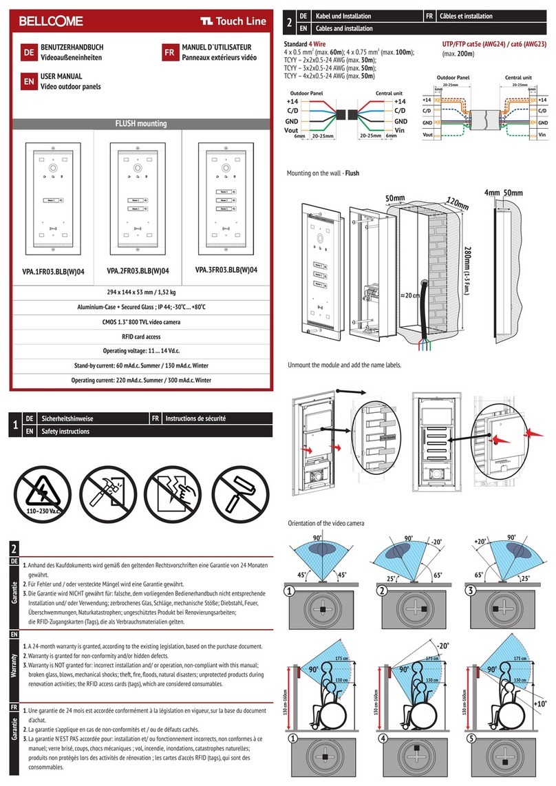
Bellcome Touch Line VPA.1FR03.BLB04 User manual

Bellcome
Bellcome KIT Audio 3 families User manual
Bellcome
Bellcome advanced 2 families User manual

Bellcome
Bellcome Touch Line VPA.1FR03.BLB04 User manual

Bellcome
Bellcome Touch Line Series User manual
Bellcome
Bellcome VPA.1FR02 User manual

Bellcome
Bellcome 2 smart User manual
