Belltech 6640 User manual

6640-888 9/05 ©
A Division of KW AUTOMOTIVE North America, Inc.
1
INSTALLATION INSTRUCTIONS
----1075 North Ave. Sanger, CA 93657-3539 toll free: 800-445-3767 web: www.belltechcorp.com----
6640
FLIP KIT
CHEVY / GMC 2 DR. TAHOE / YUKON
Congratulations! You were selective enough to choose a BELLTECH PRODUCT. We have spent
many hours developing our line of products so that you will receive maximum
performance with minimum difficulty during installation.
Note: Confirm that all of the hardware listed in the parts list is in the kit. Do not begin installation if
any part is missing. Read the instructions thoroughly before beginning this installation.
Warning: DO NOT work under a vehicle supported by only a jack. Place support stands securely under
the vehicle in the manufacturer’s specified locations unless otherwise instructed.
Warning: DO NOT drive vehicle until all work has been completed and checked. Torque all hardware to
values specified.
Reminder: Proper use of safety equipment and eye/face/hand protection is absolutely necessary when
using these tools to perform procedures!
NOTE: This is a complex installation that requires trimming of the rear chassis rails and cross members. It
should not be attempted by someone without the proper tools and some experience in installations of this
type. This installation may also require exhaust system modification to re-route the tailpipe aft of the muffler.
We recommend that the installation be performed by a qualified mechanic or repair facility.
RECOMMENDED TOOLS:
•Properly rated floor jack, support stands, and wheel chocks
•Combination wrench set
•Torque wrench: 0-75 lb ft. range
•Ratcheting socket wrench and socket sets
•Safety Glasses
KIT INSTALLATION
1. Open the hardware kit and remove all of the contents. Refer to the part list (Page 5) to verify that all
parts are present.
2. Park the vehicle on a smooth, level concrete or seasoned asphalt surface and activate the parking
brake. Block the FRONT wheels of the vehicle with appropriate wheel chocks; making sure the
vehicle’s transmission is in 1
st
gear (manual) or “Park” (automatic).
3. Raise the rear of the vehicle off the ground using a floor jack rated for this load. Position a set of jack
stands rated for this load under the frame rails just forward of the rear leaf spring forward hangers.
Lower the vehicle down onto the jack stands and verify the vehicle stability on the jack stands with the
floor jack located under the center of the rear axle housing.
4. Remove, and set aside, the rear wheels and tires.

6640-888 9/05 ©
A Division of KW AUTOMOTIVE North America, Inc.
2
5. Locate the floor jack under the center of the rear axle housing and raise the floor jack until it touches
the rear axle housing. Raise the rear axle housing another 1” to 1-1/2” to slightly preload the rear leaf
spring.
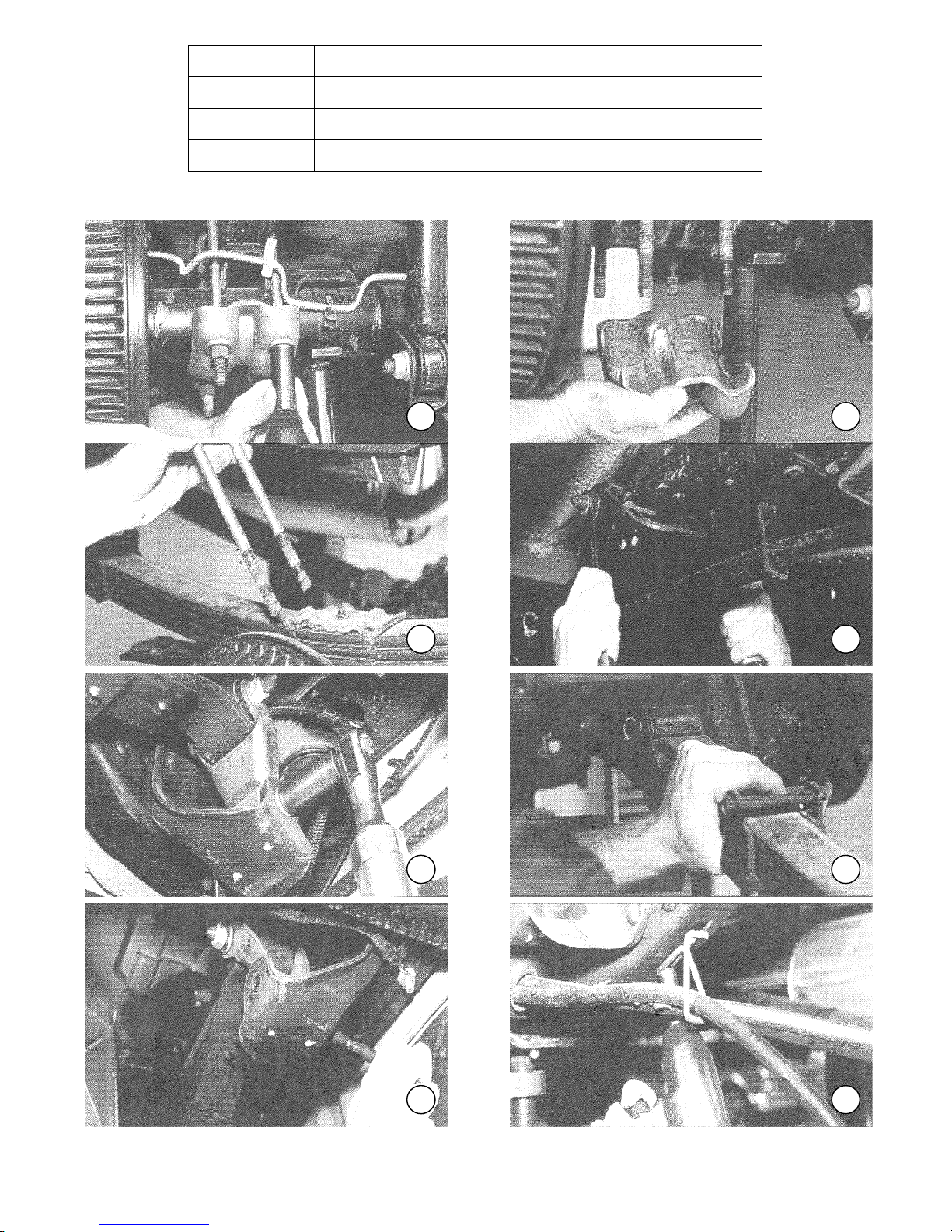
6. Remove the U-bolt nuts, washers and axle support stamping. Remove the U-bolts and upper leaf
spring plate. (PHOTO 1, 2 & 3)
7. Lower the rear axle housing until it is clear of the leaf spring assembly. CAUTION: DO NOT lower the
rear axle housing to the point that the rear brake lines are under any tension. Loosen the forward leaf
spring eyebolt and rear leaf spring eye and shackle eye bolts. (PHOTO 4 & 5)
8. Supporting the ends of the leaf spring assembly, remove the forward leaf spring eyebolt and rear
shackle eyebolt. (PHOTO 6 & 7) Remove the leaf spring assembly.
9. On the driver side of vehicle, remove the emergency brake cable-securing clip and remove the
emergency brake cable from the forward leaf spring hanger bracket by cutting away the portion of the
hanger that contains the cable housing. (PHOTO 8 & 9)
10. CAUTION: When cutting the hanger to remove the brake cable, do not cut or nick the cable, as
emergency brake system function could be impaired. CAUTION: Always wear eye protection when
using power tools.
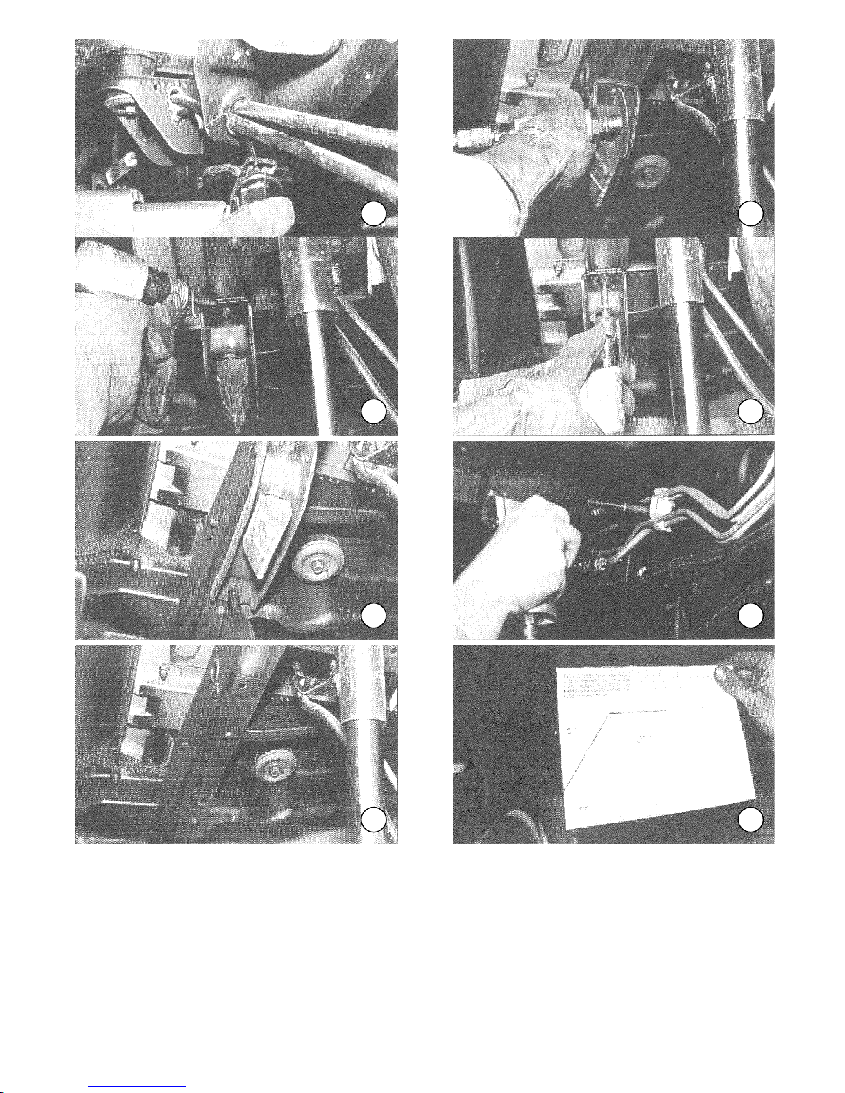
11. Remove the OEM bump stops by grinding a slot in the head of the rivet that secures the bump stop
bracket to the chassis. (PHOTO 10) Using an air chisel, or suitable tool, remove the slotted rivet head.
(PHOTO 11) Using an air chisel, or suitable tool, remove the remaining rivet shank from the bracket
and frame rail. (PHOTO 12) Remove the bolt in the forward portion of the bump stop bracket and
remove the bracket. (PHOTO 13) CAUTION: Be aware of fuel, brake and electrical components
inside of the frame rail when removing the rivet shank from the bump stop bracket. CAUTION:
Always wear eye protection when using power tools.
12. In the inside of the frame rail on the driver side of the vehicle there are three(3) plastic clips that secure
the brake and fuel lines to the inside of the frame rail. Remove the bolts that secure these clips to the
frame rail. (PHOTO 14 & 15) Also, there are several plastic ties that secure the electrical wire harness
to the inside of the frame rail, remove these ties as well. (Refer to PHOTO 15) Secure the brake, fuel
and electrical components as far away from the chassis rail as possible.
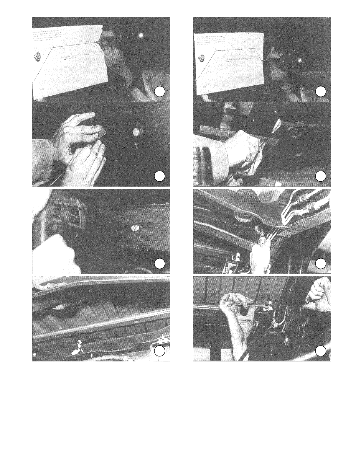
13. Locate the fuel line clip bolt hole that is forward of the rear axle. Secure the kit-supplied template to the
frame rail using this hole, and the bolt that came out of it, according to the instructions on the template.
(PHOTO 16)
14. Using a center punch, or suitable tool, transfer the locations marked as “B” from the template onto the
frame rail. (PHOTO 17) Also follow the angled lines on the template to the lowest point that these lines
are still on the frame. Transfer this location to the frame rail with the center punch. (PHOTO 18)
Remove the template from the frame and connect the transferred locations with a scribe or suitable
tool, (PHOTO 19) at the point that the scribed lines run off of the chassis scribe a line at right angles to
the chassis rail. (PHOTO 20)
15. Using a 3/8” drill bit, drill through the frame rail at the points that correspond with the “B” locations from
the template. (PHOTO 21) CAUTION: Be aware of the fuel, brake and electrical components inside
the frame rail when drilling through the frame, so as not to cause damage to these components.
CAUTION: Always wear eye protection when using power tools.

6640-888 9/05 ©
A Division of KW AUTOMOTIVE North America, Inc.
3
16. Using a die grinder with a cutoff wheel, or suitable tool, cut out the section of the frame rail marked by
the transferred locations from the template. CAUTION: Be aware of the fuel, brake and electrical
components inside the frame rail when cutting through the frame, so as not to cause damage to these
components. CAUTION: Always wear eye protection when using power tools.
17. Remove the two rivets that exist in the lower frame rail just forward and aft of the removed frame
section by grinding slots in the rivet heads using a die grinder with a cutoff wheel, or suitable tool.
Remove the heads of the rivets with an air chisel, or suitable tool. Drive the remaining rivet shanks
through the frame rail with an air chisel or suitable tool. CAUTION: Do not grind through the rivet
heads into the lower flange of the frame rail; also, be aware of the fuel, brake, and electrical
components inside the frame rail when driving the rivets through the frame. CAUTION: Always
wear eye protection when using power tools.
18. Trim the frame cross member that intersects the frame rail cutout to a height that is parallel with the
bottom of the frame rail cutout. (PHOTO 22) The middle aft section of this frame cross member must
be trimmed up to the top of the frame cross member so that the rear axle housing has clearance upon
full suspension compression. (PHOTO 23) CAUTION: Always wear eye protection when using
power tools.
19. The rear axle housing vent hose must be relocated and the original mounting strap trimmed off to
insure rear axle housing clearance during suspension compression. Remove the bolt that secures the
rear axle-housing vent to mount. (PHOTO 24) Open the vent tube clamp enough so that it can be
moved on the vent tube. Relocate the vent tube clamp to the existing hole in the fuel tank forward
cross member. (PHOTO 25) Install the kit-supplied hardware and torque to 15 Ft.-lbs. Trim off the vent
tube mount forward of the brake hose union. (PHOT 26) CAUTION: Always wear eye protection
when using power tools. Exercise caution when cutting near brake system components so that
damage does not disable the brake system.
20. Trim the front middle edge of the fuel tank retaining cross member directly behind the rear axle
housing approximately 7” wide and 1” deep so that the rear axle housing rear cover has sufficient
clearance upon full suspension compression. (PHOTO 27) NOTE: There is an electrical system
harness that lies on top of the cross member, remove the bolt and clip that retain this electrical
harness before any trimming is accomplished. After the trimming operation, replace the harness and
securing hardware. CAUTION: Always wear eye protection when using power tools.
21. Open up the underbody cross member directly over the center of the drive shaft by locating the kit
supplied template on the cross member and marking the cross member according to template
instructions. Cut out the marked section of the underbody cross member. (PHOTO 28 & 29)
CAUTION: Always wear eye protection when using power tools.
22. Position the kit supplied frame reinforcement on the frame, aligning the small hole in the reinforcement
with the vacant bolthole in the chassis rail. Clamp the reinforcement in place using c-clamps or a
suitable tool.
23. Using the frame reinforcement as a guide, drill through the frame rail at the 4 forward and 4 aft, and ½
“holes in the reinforcement using a ½” drill bit. (PHOTO 30) CAUTION: Be aware of the fuel, brake and
electrical components inside the frame rail as the frame is being drilled. CAUTION: Always wear eye
protection when using power tools. NOTE: The drilling operation can be eased by starting off with
a smaller “pilot” drill bit and working up gradually in drill bit size to this final drill bit size.
24. De-burr the drilled holes in the frame rail and install the kit supplied ½” hardware. Torque the hardware
to 100-120 Ft.-lbs. After the bolts that secure the frame reinforcement to the side of the chassis are
torqued, drill through the forward and aft holes in the bottom of the frame reinforcement and install the

6640-888 9/05 ©
A Division of KW AUTOMOTIVE North America, Inc.
4
kit supplied ½” hardware in these holes. Torque these bolts to 110-120 Ft.-lbs CAUTION: Be aware of
the fuel, brake and electrical components inside the frame rail as the frame is being drilled. CAUTION:
Always wear eye protection when using power tools. NOTE: The fuel and brake rigid lines should
be re-secured to the chassis rail with the original hardware and clips wherever possible. Use the kit
supplied “zip ties” to secure the electrical harness to the chassis brake lines to the kit supplied ½”
hardware. These rigid lines must be reconfigured as necessary so that they do not have contact with
any other parts.
25. Install the kit supplied elastic bump stop in the hole in the bottom center of the frame reinforcement
raised section. (PHOTO 31) Reconfigure fuel and brake lines as necessary to prevent line contact with
the other hardware.
26. Remove the front leaf spring hanger from the chassis by grinding slots in the heads of the hanger
securing rivets. (PHOTO 32) In the same manner as previously used, remove the slotted rivet heads
with an air chisel or suitable tool, and drive the remaining rivet shanks through the hanger and chassis
using an air chisel or suitable tool. CAUTION: Be aware of fuel, brake and electrical components
behind the frame rail when driving the rivets through the frame.
27. Drill out the vacated rivet holes using a ½” drill bit. (PHOTO 33) CAUTION: Be aware of fuel, brake
and electrical components behind the frame rail when drilling through the frame. De-burr these holes
and secure the kit supplied hanger to the frame rail using the kit supplied ½” hardware. (PHOTO 34)
Torque this ½” hardware to 110-120 Ft.-lbs.
28. Jack up the rear axle housing to the point that the rear leaf spring can be re-installed under the rear
axle housing. Install the kit supplied forward leaf spring eyebolt and nut and the shackle eyebolt and
nut, but do not tighten to final torque at this time.
29. Locate the kit supplied rear axle housing saddle over the leaf spring assembly center bolt with the hole
in the bottom of the saddle located forward of the part centerline. (PHOTO 35) Lower the rear axle
housing down into the saddle. Install the kit supplied U-bolts, leaf spring support plate and U-bolt
hardware, but tighten the U-bolt nuts only as necessary to maintain contact of all parts and not to final
torque at this time.
30. Repeat steps 4 through 27, as necessary, for the remaining side of the vehicle.
31. Remove, and put aside, the lower shock absorber hardware and swing the shock absorbers out of the
immediate work area. Remove the right hand emergency brake cable-retaining clamp from the cable
and discard the larger half of the clamp assembly.
32. Install the kit supplied shock absorber extensions with the crush-prevention sleeves between the “legs”
of the original shock absorber mounts. Torque the kit supplied hardware to 81 Ft.-lbs (PHOTO 36)
Attach the previously removed right hand emergency brake clamp to the rear of the right hand shock
extension with the kit supplied hardware and torque the 5/16” hardware to 12 Ft.-lbs. (PHOTO 37)
33. Install the lower shock absorber eye into the shock mount extension and torque the retained hardware
to 81 Ft.-lbs. NOTE: The stock shock absorbers may be too long for this application and a
quality aftermarket shock absorber should be fitted there if any question as to whether the
stock shock has enough travel for this application.
NOTE:
34. Placement of the exhaust system tailpipe should be analyzed at this point to determine if it extends
below a line sighted between the bottom of the frame reinforcement mounted bump stops. The

6640-888 9/05 ©
A Division of KW AUTOMOTIVE North America, Inc.
5
exhaust system should be a minimum of 1” above a line sighted between these points. If this
specification is not met, the exhaust system must be modified to accomplish this clearance.
35. Install wheels and tires. Torque the lug nuts to 120 Ft.-lbs.
36. Torque the rear axle retaining U-bolts to 85-110 Ft.-lbs. Raise the rear of the vehicle to clear the jack
stands. Remove the jack stands and lower the vehicle to the ground. Torque the rear leaf spring
forward eyebolt to 92 Ft.-lbs. and the rear leaf spring eye and shackle eyebolt to 81 Ft.-lbs.
37. Installation is complete. Check all of the hardware and re-torque at intervals for the first 10, 100, 1000
miles.
PART LIST FOR 6640 FLIP KIT
PART No. DESCRIPTION QTY.
6640-001 C-Section L/H 1
6640-003 C-Section R/H 1
6640-005 Spring Hanger L/H 1
6640-007 Spring Hanger R/H 1
6550-050 Shock Mount Extension 2
6600-005 Saddle 2
6600-010 U-Bolt Plates 2
6650-003 5/8”-18 x 9” U-Bolts 4
110502 5/8” A325 Flat washer 8
110505 5/8”-18 Ny Lock Nut 8
110456 9/16”-18 x 3-1/2” Grade 8 Bolt 2
110670 9/16” A325 Flat Washer 8
110454 9/16”-18 Ny Lock Nut 2
110408 ½”-20 x 1-1/4” Grade 8 Bolt 24
110402 ½”-20 Grade C Lock Nut 28
110660 ½” A325 Flat Washer 56
7000-880 Shock Sleeve 2
4918-001 Bump Stop 2
110201 5/16”-18 x 1” Grade 8 Bolt 3
110203 5/16”-18 Ny Lock Nut 3
110204 5/16” A325 Flat Washer 6
6640-888 9/05 ©
A Division of KW AUTOMOTIVE North America, Inc.
6
111125 14mm x 2.0 x 115mm Grade 8 Bolts 2
111135 14mm x 2.0 Grade C Nut 2
6640-188 Template 1
110409 HHCS ½” –20 x 1 ½” 4
1
2
34
56
78
6640-888 9/05 ©
A Division of KW AUTOMOTIVE North America, Inc.
7
9
10
11
12
13
14
15
16
6640-888 9/05 ©
A Division of KW AUTOMOTIVE North America, Inc.
8
17
18
19
20
21
22
23
24

6640-888 9/05 ©
A Division of KW AUTOMOTIVE North America, Inc.
9
25
26
27
28
29
30
31
32

6640-888 9/05 ©
A Division of KW AUTOMOTIVE North America, Inc.
10
33
34
35
36
37
Table of contents
Other Belltech Automobile Accessories manuals


Popular Automobile Accessories manuals by other brands


Cruz
Cruz Evo Rack Alu A23-140 Assembly instructions

ConWys
ConWys 12270535C Fitting instructions

Whispbar
Whispbar K444 Fitting Instructions for Basic Carrier

Alu-Cab
Alu-Cab SH-BKT-KH Fitment Instructions

DVB
DVB TCBR-01 installation manual

Continental Refrigerator
Continental Refrigerator ContiConnect installation manual