Bempu ApneBoot User manual

OPERATION MANUAL
TM

www.bempu.com
Disclaimer
All rights reserved. BEMPU Health Pvt. Ltd. reserves the right to revise spec-
ications and features shown herein, or discontinue the product described
herein at any time without prior notice or obligation. The contents of the
document are provided “as is”. Please check with BEMPU representative for
the most current information or any query.

www.bempu.com
About the company
BEMPU Health Pvt Ltd. provides a range of innovative and high-quality infant
healthcare products. You can nd out more at www.bempu.com .
Manufactured and Marketed by
BEMPU Health Pvt. Ltd.,
3C, 3rd Floor, Alsa Glenridge Apartment
32, Langford Road, Shanti Nagar,
Bengaluru, Karnataka, India 560027
BEMPU Customer Support
Email Address: [email protected]
For India 1 (800) 425 0192 (toll free)
Or
For Whatsapp and Calling +91 - 9481 841 872

www.bempu.com
ABOUT THE MANUAL
This manual contains necessary information for safe and proper setup and
use of the BEMPU ApneBoot device. Important safety information relating to
general use of the BEMPU ApneBoot is conveyed in this manual.
The BEMPU ApneBoot is subsequently referred to as ApneBoot, Pulse Rate
as PR and Oxygen Saturation as SpO2 throughout this manual.
Before using the ApneBoot, read the operation manual carefully for a thor-
ough understanding of the indications, contraindications, warnings, precau-
tions and safe operation. Only qualied service personnel should service this
product.
Caution: Rx Only.
Caution: This device should be used by trained medical personnel only.

www.bempu.com
CONTENTS
1. Product Description 7
1.1 Indications for Use and Contraindications 7
1.2 Declaration of Substances Usage 8
1.3 Device Details 8
2. Device Setup 11
2.1 Unpacking and Inspection 11
2.2 Setup 11
2.3 Preparation for Use 12
2.4 Method of Probe Placement 13
3. Operation 15
3.1 Main Screen 15
3.2 Conguring the Settings 18
3.3 History Button 22
3.4 Alarms and Indications 23
3.5 Operational States 24
4. Troubleshooting 27
4.1 Device 27
4.2 Safety 28
4.3 Warnings and Cautions 29
4.4 Specications 33
4.5 Guidance and manufacturer’s declaration-
Electromagnetic emissions 36
4.6 Guidance and manufacturer’s declaration-
Electromagnetic immunity 37
4.7 Recommended separation distances between portable
and mobile RF communications equipment and device 40
4.8 Symbols for packaging and Instructions 41
5. Service and Maintenance 43
5.1 Cleaning 43
5.2 Repair Policy 44
5.3 Return Procedure 44
5.4 Disposal of Device 44
BEMPU Customer Support Contact Details 45
Warranty 45
Exclusions from Warranty 45
No Implied License 47

6www.bempu.com

7www.bempu.com
1. PRODUCT DESCRIPTION
BEMPU ApneBoot is a pulse oximeter-based device that helps primary
apneas. It uses an inbuilt pulse-oximeter to monitor oxygen saturation and
pulse rate. In the event of apnea, as indicated by bradycardia and/or oxygen
desaturation, it uses a stimulator that vibrates the foot sole of the infant, to
stimulate the nervous system to restart breathing. The device also provides
an audio-visual alarm to get the caretakers attention to rapidly intervene
before any injury can occur.
The device operates on alternating current and also has an inbuilt battery to
provide a power backup of up to 12 hours.
1.1 Indications for Use and Contraindications
ApneBoot is intended to be used in clinical settings and mobile environments
like inter and intra-hospital transport, by trained medical personnel only. It
is intended to be used on preterm infants (with stimulation) and all infants
(without stimulation).
ApneBoot identies apnea through bradycardia and/or oxygen desaturation
and not by respiration rate.
NOTE: All bradycardia and oxygen desaturation events may or may not coin-
cide with an apneic event marked by cessation of breathing.
The ApneBoot is designed to provide safe stimulus to help resolve primary
apneas which are central in nature. It cannot resolve secondary or obstruc-
tive apneas.
The device is not intended to be used with highly critical infants who are kept
on ventilator support and/or any life support devices.
The device is not designed to be used at home and/or by any non-clinical
untrained sta.
Do not use this device in an MR environment.
Explosive Hazard: Do not use this device in an explosive atmosphere or in the
presence of ammable anesthetics or gases
This device does not meet debrillation-proof requirements per IEC 60601-1.
8www.bempu.com
1.2 Declaration of Substances Usage
ApneBoot is a non-invasive device and does not include any bio-substances
or tissue derivatives. The product is intended to be used in clinical settings
like hospitals.
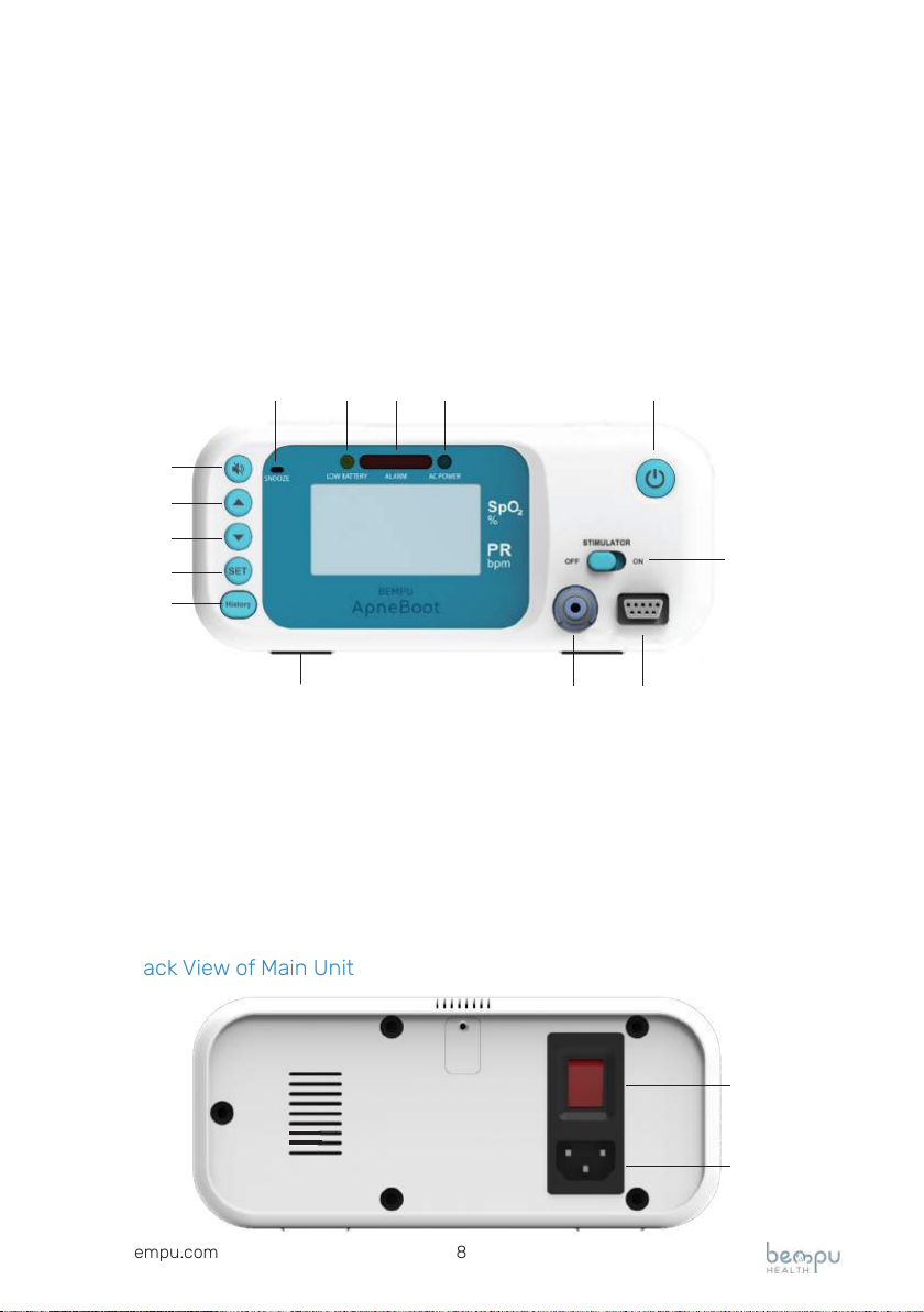
1.3 Device Details
1.3.1 Front View of Main Unit
1. Power Button 8. AC Power LED Indicator
2. Stimulator ON/OFF Switch 9. Alarm Snooze Button
3. Pulse Oximeter Probe Connector 10. Upward selection Button
4. Stimulator Boot Connector 11. Downward selection Button
5. Snooze LED Indicator 12. Set Button
6. Low Battery LED Indicator 13. History Button
7. Alarm LED Indicator 14. Base Pads
1.3.2 Back View of Main Unit
9
10
11
12
13
5 6 7 8 1
2
4 3
14
15
14

9www.bempu.com
14. AC Power ON/OFF Switch
15. AC Power Cord Connector
1.3.3 Stimulator Boot
The stimulator boot is the vibrating module which is wrapped around the
infant’s foot sole.
1.3.4 Pulse Oximeter Probe
The pulse oximeter probe is the sensor that is placed and wrapped around
the infant’s foot or any peripheral body site suitable for measuring oxygen
saturation and pulse rate.

10www.bempu.com

11www.bempu.com
2. DEVICE SETUP
This section contains step-by-step instructions on setting up and operating
the ApneBoot. It is advisable to go through this section in detail before using
the device. In case of any questions or concerns clarify with a BEMPU repre-
sentative before operating the device.
2.1 Unpacking and Inspection
This product must be checked before use. A defective product should not be
used. Parts that are broken, missing, distorted, or contaminated should be
replaced immediately. When such repair or replacement becomes necessary,
BEMPU recommends that a telephone request for service advice to be made
to BEMPU Health Pvt. Ltd. on the given Customer Support number (1800-
425-0192).
Before operating the ApneBoot check for the following and do not use if
there are any signs of damage as described below:
a) Packaging is damaged
b) Device or any of the accessories are physically damaged
c) Any of the described box contents are missing
The ApneBoot product purchase contains the following:
ApneBoot Main Unit 01
Pulse Oximeter Probe 01
Patient Extension Cable 01
Stimulator Boot 01
AC Power Cord 01
Instruction Manual 01
2.2 Setup
Step 1: Place the device on a at, horizontal and dry surface.
Caution: Make sure nothing is stacked up or placed above the main unit
blocking the speaker.
Note: Make sure that the device is placed in a manner to be easily visible and
readable.

12www.bempu.com
Step 2: Connect the power cord to the AC power cord connector and then
connect it to an AC power supply.
Step 3: Connect Pulse Oximeter Probe and Stimulator Boot to the device in
the respective slots given on the front panel of the main unit.
2.3 Preparation for Use
Step 1: Turn on the ApneBoot Device
(i) AC Powered:
Connect the AC power supply cord at the back panel of the device and turn
ON the AC power supply switch. The AC power switch turns RED. Now, turn
the power button on the front panel ON.
When the screen turns ON the following should appear as a part of the acti-
vation sequence.
1. The BEMPU logo appears
2. An audio alarm tone plays
3. Alarm LED blinks RED
4. Stimulator Boot vibrates
If you don’t nd the device turning on, please check the power cord and
repeat step 1. Call the BEMPU Customer Support number if the problem
persists and if the device fails to turn on even after all the connectors are
connected as described.
(ii) Battery Powered:
Turn ON the device using the power button given on the front panel. If there
is enough battery, the screen will turn ON and the following should appear as
a part of the activation sequence.
1. The BEMPU logo appears
2. An audio alarm tone plays
3. Alarm LED blinks RED
4. Stimulator Boot vibrates
If the device does not turn ON, change the battery by connecting the device
to AC power. If problem persists, call the BEMPU Customer Support number.
Step 2: Make sure that the device detects the probes and the screen does
NOT display following error messages:

13www.bempu.com
a) Probe Not Connected
It indicates that the pulse oximeter probe cable is not connected to the main
unit.
b) Stimulator Not found
It indicates that the stimulator boot cable is not connected to the main unit.
Step 3: Connect the device to the infant.
(i) Placement of Pulse Oximeter Probe: Place the Pulse Oximeter Probe on
the infant’s foot or other peripheral body site, suitable for measuring pulse
oximeter based oxygen saturation and pulse rate.
(ii) Placement of the Stimulator Boot: The stimulator boot must be wrapped
against the foot sole of the infant snuggly, neither too tight nor too loose.
Ensure that the stimulator wire passes through the toe side and not through
the heel side.
WARNING: The stimulator boot should ONLY be placed on the foot
sole and not on any other body site.
WARNING: Do not put the stimulator boot if the infant’s foot has any
skin allergies and is chapped/itchy/red. This may result in aggravation of the
allergy.
WARNING: Clean the probes using surgical spirit and cotton swab
before placing it against the infant’s foot sole. Refer to cleaning instructions
in Section 5.1.
The pulse oximeter probe will start measuring the infant’s Pulse (PR) and
Oxygen Saturation (SPO2). Make sure the device continuously displays both
the values on the screen of the unit. If not, check the placement of the Pulse
Oximeter Probe.
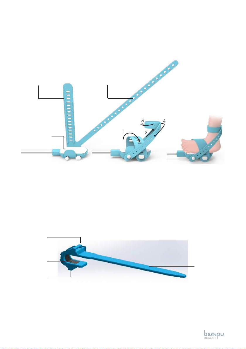
2.4 Method of Probe Placement
(i) Stimulator Boot
Place the stimulator boot on the infant’s foot sole with toes pointing in the
direction of wire.
Wrap the strap (a) over the foot in the direction marked as 1 in the below im-
age. Lock the strap (a), so that there is a rm tting of the foot.
!
!
!
14www.bempu.com
Wrap the belt (b) around the ankle of the infant. Initially, move the belt along
the leg in the direction marked as 2, then wrap around the leg (direction
marked as 3), and nally bring the belt (b) towards the wire (direction marked
as 4) so that it can be locked for a good t around the ankle.
(ii) Preparation of the Pulse Oximeter Probe
Place the pulse oximeter probe on the infant’s foot or any peripheral body
site suitable for monitoring oxygen saturation and pulse rate and wrap the
strap around the site. Secure the strap through the two loops and make sure
the pulse oximeter probe is tted snugly.
Once the pulse oximeter probe is correctly placed onto the foot, the screen
will display the SpO2 and PR values within 10 seconds. If not, then the screen
will show “Probe o patient”. Readjust the probe for proper placement.
12
34
Strap (a) Strap (b)
Loop 2
Loop 1
Sensor Strap
Stimulator
Capsule

15www.bempu.com
3. OPERATION
3.1 Main Screen
1. Operating Keys
The alarm snooze button snoozes the alarm for 60 seconds and the Snooze
LED turns RED.
There are two selection keys provided for controlling the upward and down-
ward direction of the cursor on the screen.
The set button helps in setting the dierent parameters, refer to the cong-
uring the settings in section 3.2.
On pressing the history button the details of desaturation and bradycardia
events are displayed. Refer to the History section 3.3.
12
3 4
Alarm Snooze Button
Upward Selection Button
Downward Selection Button
Set Button
History Button

16www.bempu.com
2. Panel Connectors and Switches
The power button is used to turn ON the main unit.
The stimulator boot vibration can be turned ON and OFF using the Stimulator
ON/OFF switch. Refer to the conguring the setting section 3.2.
The stimulator boot is connected to the main unit at the stimulator boot
connector.
The pulse oximeter probe is connected to the main unit at the pulse oximeter
probe connector.
3. LEDs
When the alarm snooze button is pressed, the snooze LED turns RED, alert-
ing the user that the alarm is snoozed.
When the main unit is battery powered and battery is low, the low battery
LED turns YELLOW.
In the event of apnea, indicated by bradycardia and/or oxygen desaturation,
Power Button
Stimulator ON/OFF Switch
Stimulator Boot Connector
Pulse Oximeter Probe Connector
Snooze Low Alarm AC
Battery Power

17www.bempu.com
along with the stimulator boot vibrations and audio alarm, the Alarm LED
blinks RED.
When the main unit is AC powered from the AC power cord which is connect-
ed at the back panel, the AC power LED turns blue.
4. Display Screen
The device displays the measured value of the oxygen saturation and pulse
rate on the right most side of the screen in a visibly large size.
The set threshold value of the oxygen saturation and pulse rate is displayed
on the left side of the measured value, in a smaller size.
The stimulation intensity of the stimulator boot set by the user is displayed
on the top left corner of the screen.
The perfusion index quality is displayed on the left side of the screen.
Oxygen
Saturation
Pulse Rate
StimMed
PI 85
GOOD
090
Stimulation
Intensity
Perfusion
Index
Quality
Threshold Measured
Value Value
18www.bempu.com
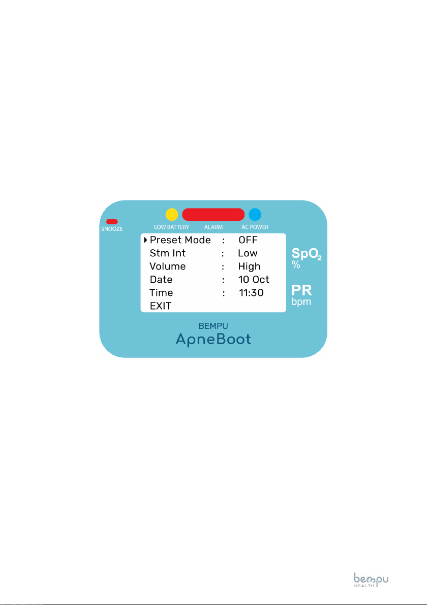
3.2 Conguring the Settings
The user can set the following parameters in the following manner:
1. Preset mode for predened thresholds of SpO2 and PR.
The device has a preset mode which includes predened threshold values
for SpO2 and PR for stimulation and alarm as described below. In the preset
mode the device will stimulate and alarm if any of the following conditions
are met:
a) If SpO2 < 85% AND PR < 100 bpm for 5 seconds
b) If SpO2 < 75% for 5 seconds
c) If PR < 90 bpm for 5 seconds
To select the PRESET mode press the SET button to open the menu screen
as shown below. Bring the cursor to Preset Mode and press the sub menu.
Select the ON option by pressing the SET button again. Use the downward
selection arrow to BACK or EXIT the menu.
2. Custom thresholds for SpO2, PR, duration of thresholds before stimulation
and alarm, the relationship AND/OR between SpO2 and PR.
When the Preset Mode is set OFF, the user can set the values for the SpO2,
PR, condition, duration before stimulation and alarm.
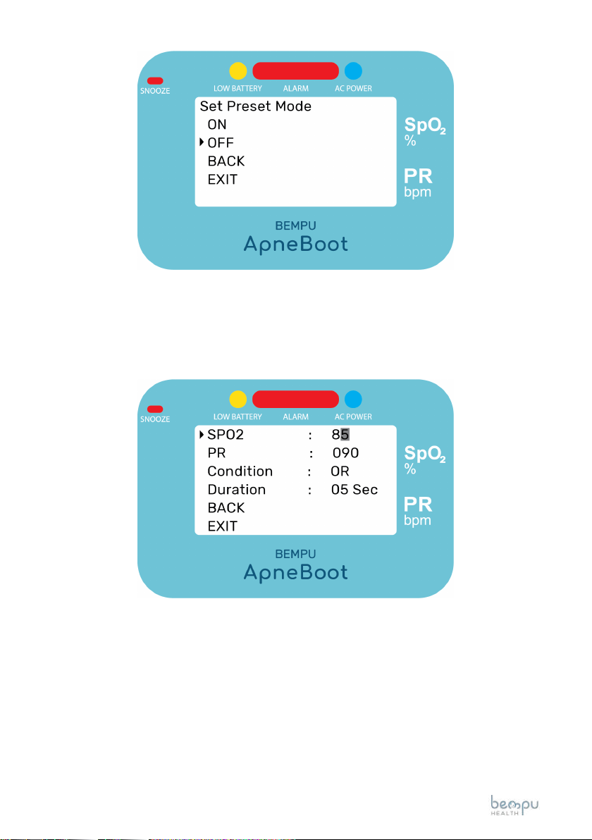
19www.bempu.com
To set the value of each of them, press the SET button to select and use the
arrow keys to change values. Pressing the SET button once more, will shift
the cursor from the units position to tens position.
Further, after setting the values, go back to the SET menu to set the other
values for stimulation intensity, volume of the alarm, date and time. Use the
downward selection button to back or exit the menu.
3. Stimulation Intensity of the boot can be set at either high, medium or low
according to the intensity of stimulation required for dierent infants.
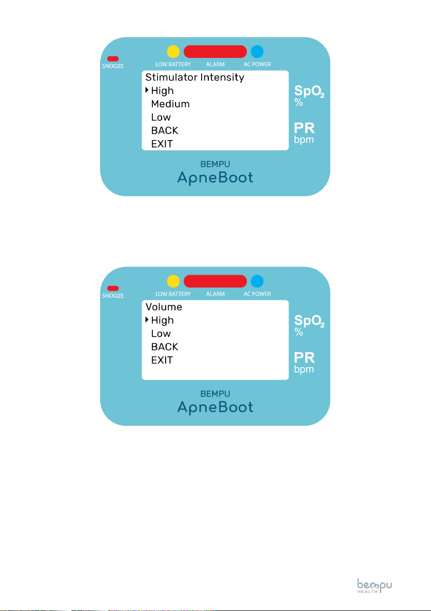
20www.bempu.com
4. The alarm volume can be set at either high or low, as per the user require-
ment.
5. The user can set the date, as required. Press the SET button when the
cursor is pointing at Date on the screen. This should display the rst screen
display on the screen.
Press the SET button once again to edit the Date and then with the help of
the upward and downward selection keys, the day, month and year can be
changed.
Table of contents


