MPI UltraScan User manual


UltraScan™ Table
Page 2 of 36 14512-L
DCR-00335
Table of Contents
Table of Contents ................................................................................ 2
Symbols and Definitions...................................................................... 4
Precautions.......................................................................................... 5
Intended Use ....................................................................................... 8
Set Up.................................................................................................. 8
Safety Features ................................................................................... 9
Operation........................................................................................... 10
Hand-Wand..................................................................................... 11
Individual Locking Casters ............................................................. 12
Single Pedal Brake (optional)......................................................... 13
Drop Sections (on select models) .................................................. 14
Back Rest (on select models)......................................................... 16
Non-Pinch Closure (on select models)........................................... 17
Manually Operated/Removable Foot-Drop Section....................... 18
Foot Board (on select models)....................................................... 19
Foot Stirrups................................................................................... 20
Removable Collection Tray (on select models) ............................. 20
Accessories ....................................................................................... 21
Safety Rails..................................................................................... 21
Sonographer’s Extension ............................................................... 23
Padded Arm Board.........................................................................24
Carotid Head Rest.......................................................................... 25
IV Pole Holder ................................................................................26
Patient Positioning Safe-T-Wedges™............................................26
Preventative Maintenance.................................................................27
Cleaning............................................................................................. 28
Troubleshooting Guide ...................................................................... 30
UltraScan™ Table Parts List ............................................................. 32
Specifications and Warranty..............................................................34
Specifications ................................................................................. 34
Warranty........................................................................................36

UltraScan™ Table
Page 3 of 36 14512-L
DCR-00335
MEDCIAL POSITIONING, INC
1146 Booth Street
Kansas City, KS 66103
UltraScan™ Table
Attribute
Rating (120V Version)
Rating (230V Version)
Voltage
120 VAC
230 VAC
Amperage
2 A
1 A
Cycle
50/60 Hz
50/60 Hz
Duty Cycle
10%, 1 min. on/10 min. off
10%, 1 min. on/10 min. off
Leakage Current
< 100 µA
< 100 µA
Maximum Distributed
Load
500 lbs.
500 lbs.
UL 60601-1 CLASSIFICATIONS:
•Class 1 Equipment
•Type B Applied Part
•Degree of Protection Against Ingress of Water / IPXO
•Equipment Not Suitable for Use in Flammable Anesthetic Mixture
All electrical circuitry is isolated from chassis.
Grounding reliability can only be achieved when the equipment is connected to
an equivalent receptacle marked “Hospital Only” or “Hospital Grade”
The power cord is to be used for mains disconnection.
MEDICAL EQUIPMENT WITH RESPECT TO ELECTRICAL SHOCK, FIRE AND
MECHANICAL HAZARDS ONLY IN ACCORDANCE WITH UL 60601-1 AND
CAN/CSA C22.2 NO. 601.1
Environment Operating Range
Temperature range within +5 to +40 C
Relative humidity range within 15% to 95%
Atmospheric pressure range within 700 to
1060 hPa
Transportation and storage:
Temperature range within -40 to 70 C
Relative humidity range within 10% to 100%
Atmospheric pressure range within 500 to
1080 hPa
UltraScan™ Table
Page 4 of 36 14512-L
DCR-00335
Symbols and Definitions
Blue circle with
white figure
holding book
Warning, follow instructions for use. Failure to comply may result in
injury.
Red circle with
line through it
with black figure
in background
Warning, stepping is prohibited. Failure to comply may result in injury.
Type B
Applied Part
Applied Part complying with specified requirements for protection
against electric shock. Type B Applied Parts are those parts, which are
usually Earth referenced. Type B are those parts not suitable for direct
cardiac application
Attention
Attention, consult accompanying documents
Protective
Earth
Any terminal which is intended for connection to an external protective
conductor for protection against electric shock in case of a fault
This device contains materials that are potentially hazardous to the
environment. In accordance with the DIRECTIVE 2002/96/EC OF THE
EUROPEAN PARLIAMENT AND OF THE CONCIL on waste electrical
and electronic equipment (WEEE), the UltraScan™ electrical system
and accessories should not be disposed as unsorted municipal waste.
Consult your instructional policies and local regulations regarding
disposal. Contact your Medical Positioning, Inc. Service
Representative if additional disposal details are required.
UltraScan™ Table
Page 5 of 36 14512-L
DCR-00335
Precautions
Your UltraScan™ Table has been pre-assembled and tested to ensure operation
on day one. Please closely inspect it when you receive it to ensure no damage
has occurred during shipment. Because it is a complex piece of equipment, make
note of the following precautions.
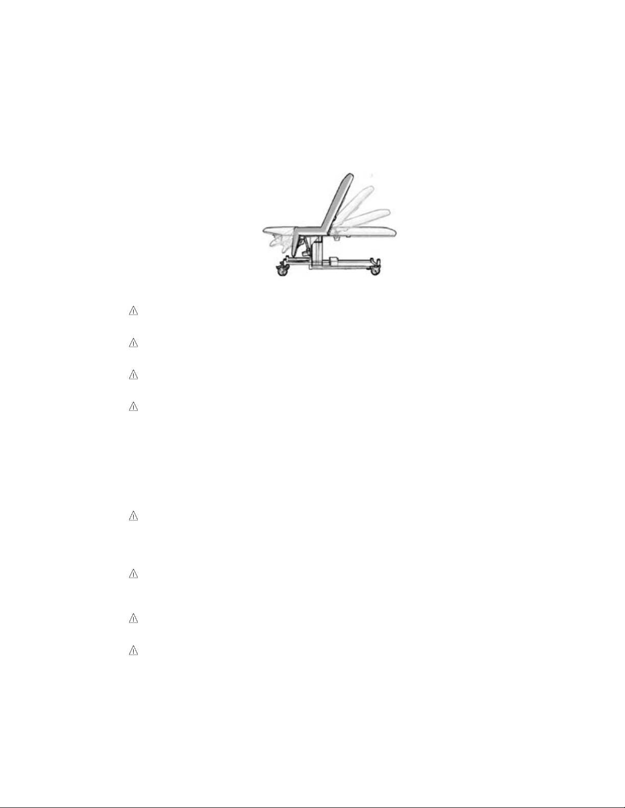
Figure 1
WARNING, POTENTIAL FOR INJURY OR DEATH. Do not leave patient
unattended while using the table.
WARNING, POTENTIAL FOR INJURY OR DEATH. Do not modify this
equipment without authorization of the manufacturer.
WARNING, POTENTIAL FOR INJURY OR DEATH. Do not use in oxygen
rich environment.
WARNING, POTENTIAL FOR INJURY OR DEATH. The foot drop section
is designed to support more weight than a patient’s legs alone, but it is
a collapsible and/or removable section and is not designed to support
full patient body weight. Never allow the patient to apply full body
weight to the extended foot drop section portion of the table while
entering or exiting the table as this may result in instability of the table.
Have the patient enter and exit the table from the side or from the foot
end with the foot section collapsed.
WARNING, POTENTIAL FOR INJURY OR DEATH. To reduce the risk of
electrical shock, grounding reliability can only be achieved when the
equipment is connected to an equivalent receptacle marked “hospital
only” or “hospital grade”.
WARNING, POTENTIAL FOR INJURY OR DEATH. To reduce the risk of
electrical shock, do not remove secured covers. Refer servicing to
qualified personnel.
WARNING, POTENTIAL FOR INJURY OR DEATH. To reduce the risk of
a potential fall, lock all casters before using equipment.
WARNING, POTENTIAL FOR INJURY OR DEATH. Once the table and
patient have been properly positioned, ensure the casters are locked
and the hand wand is placed in a safe position to prevent incidental
contact and unwanted movement of the table surface during the
procedure.

UltraScan™ Table
Page 6 of 36 14512-L
DCR-00335
WARNING, POTENTIAL FOR INJURY. To reduce the risk of a potential
fall, do not use the product to transport patient between rooms or over
thresholds.
WARNING, POTENTIAL FOR INJURY. Avoid placing your hand in or
near the drop section mechanism during operation
WARNING, POTENTIAL FOR INJURY OR DEATH. After closing, always
lift up on the drop section to assure that is totally locked before patient
entry or exit.
WARNING, POTENTIAL FOR INJURY. Failure to hold the back rest
when the lever release lever will result in the back rest lowering
suddenly, possibly causing injury to the patient.
WARNING, POTENTIAL FOR INJURY. Do not operate drop section or
back rest if non-pinch closure flap is absent. The flap is attached to the
bed with hook and loop tape and can easily be adjusted whenever
necessary.
WARNING, POTENTIAL FOR INJURY OR DEATH. Verify both sides of
the food drop section’s hinges have the pivot locks engaged when
raising the foot section. Failure to have both pivot locks engaged can
result in sudden lowering of the foot drop section.
WARNING, POTENTIAL FOR INJURY. Keep hands clear of the foot
section hinges during operation.
WARNING POTIENTIAL FOR INJURY. Periodically check both sides of
the foot drop section’s hinges to make sure they are between the
receivers mounted on both sides of the table’s frame.
WARNING, POTENTIAL FOR INJURY. Use care to firmly hold the
removed foot drop section. Failure to hold the foot drop section could
result in dropping the foot drop section.
WARNING, POTENTIAL FOR INJURY OR DEATH. Always raise the foot
board when in reverse Trendelenburg (foot end down) positions greater
than 15°. Failure to raise the foot board may result in the patient sliding
off the table surface.
WARNING, POTENTIAL FOR INJURY OR DEATH. The foot board is
designed to support more weight than a patient’s legs alone, but it is a
collapsible a section and is not designed to support full patient body
weight. Never allow the patient to apply full body weight to the
extended foot board while entering or exiting the table as this may
result in instability of the table. Have the patient enter and exit the table
from the side or from the foot end with the foot section collapsed.
WARNING, POTENTIAL FOR INJURY. Keep hands clear of the foot
board hinges during operation.
WARNING, POTIENTIAL FOR INJURY. The foot board is collapsible and
thus care should be taken when lowering the foot board to avoid
closing on the patient’s feet and/or legs.
WARNING, POTENTIAL FOR INJURY OR DEATH. The foot stirrup is
designed to support more weight than a patient’s legs alone, yet is not

UltraScan™ Table
Page 7 of 36 14512-L
DCR-00335
designed to support full patient body weight. Never allow the patient to
apply full body weight to the foot stirrup.
WARNING, POTENTIAL FOR INJURY OR DEATH. Always verify the
safety rail is securely latched in the up position before using the table
with the safety rail raised. Failure to have the safety rail latched in the
raised position may result in a patient fall.
WARNING, POTENTIAL FOR INJURY. Securely tighten the Hand Wheel
for the padded arm board prior to performing any procedures utilizing
the padded arm board.
WARNING, POTENTIAL FOR INJURY. Securely tighten the adjustment
knobs for the carotid head rest prior to performing any procedures
utilizing the carotid head rest.
CAUTION, PRODUCT DAMAGE MAY RESULT. Secure hand wand with
hook and loop fastener when not in use. Keep cable clear of moving
parts.
CAUTION, PRODUCT DAMAGE MAY RESULT. It is not necessary to
"slam" the arm board closed. Slamming the arm board closed will
startle the patient and may result in damage to the mechanism.
CAUTION, PRODUCT DAMAGE MAY RESULT. Protect vinyl upholstery
from sharp objects and abrasion to avoid damage.
CAUTION, PRODUCT DAMAGE MAY RESULT. Refer to instructions
located in this manual for vinyl cleaning recommendations.
CAUTION, PRODUCT DAMAGE MAY RESULT. Do not use abrasives to
clean painted surfaces.

UltraScan™ Table
Page 8 of 36 14512-L
DCR-00335
Intended Use
The product is intended for use with general ultrasound systems. The product is
intended for the environment where ultrasound systems are used, including
hospitals, outpatient facilities, and doctor’s offices. The product is
contraindicated for patients that cannot safely sit in a chair or lie on an elevated
surface.
WARNING, POTENTIAL FOR INJURY OR DEATH. Do not leave patient
unattended while using the table.
WARNING, POTENTIAL FOR INJURY OR DEATH. Do not modify this
equipment without authorization of the manufacturer.
WARNING, POTENTIAL FOR INJURY OR DEATH. Do not use in oxygen
rich environment.
Set Up
Your UltraScan™Table has been shipped to you in “plug and play” condition.
After unpacking the product, we recommend performing an initial test of your
UltraScan™Table to ensure that each function is in correct working order. After
reviewing this manual you are ready to begin using your UltraScan™Table.
System Test Procedure
The hand-wand is a low voltage, DC operated device. The cable begins at the
hand wand and plugs into the control box.
WARNING, POTENTIAL FOR INJURY OR DEATH. To reduce the risk of
electrical shock, grounding reliability can only be achieved when the
equipment is connected to an equivalent receptacle marked “hospital
only” or “hospital grade”.
STEP
ACTION
1
After removing padding and packaging materials, locate primary
power supply cord and attach to suitable grounded outlet.
2
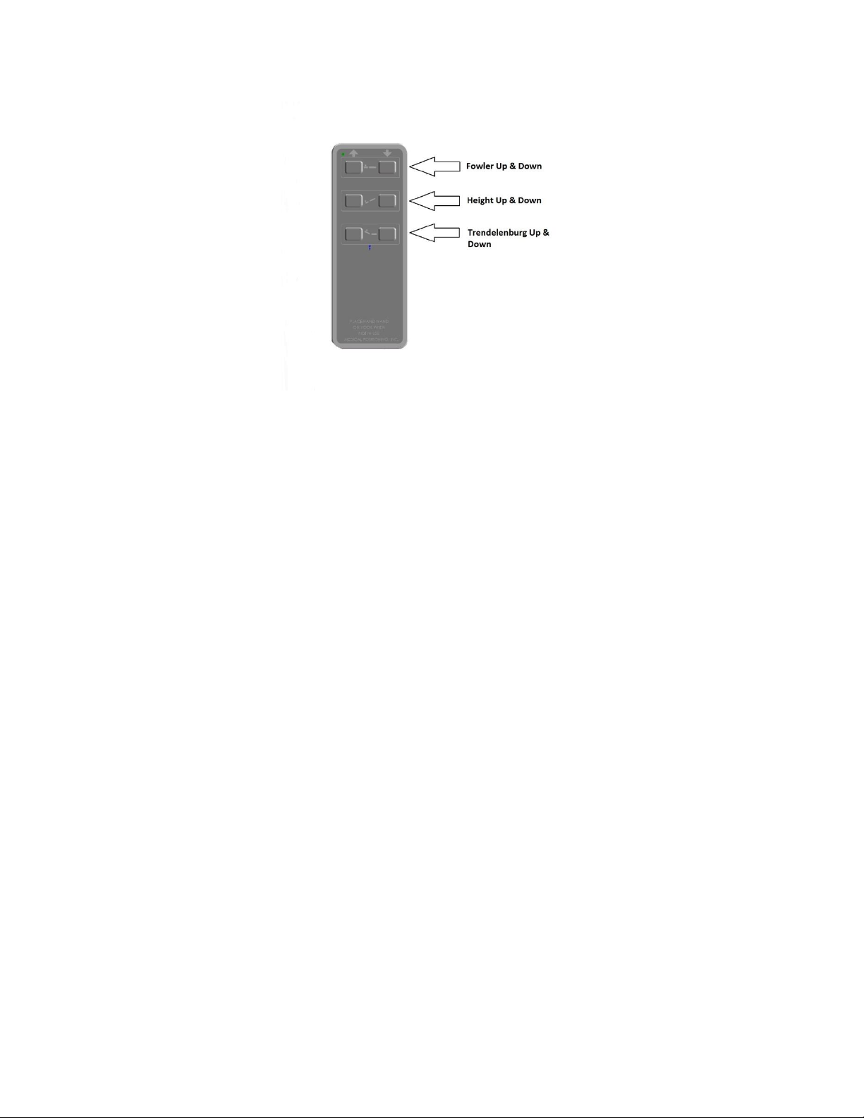
To test actuator function, locate the hand-wand and depress each
function button one at a time. (Depressing multiple buttons
simultaneously will prevent the motor from operating.) Figure 2.
3
If any function does not operate, perform the test procedures listed
in the Troubleshooting Guide
Isolation from the external electrical supply can be obtained by unplugging the
power cord from the wall outlet or by unplugging the power cord from the control
box.
UltraScan™ Table
Page 9 of 36 14512-L
DCR-00335
Figure 2
Only select models have Trendelenburg functionality.
Safety Features
•This product is equipped with multiple automated safety features to prevent
danger or damage during use. The entire system is electrically isolated to
UL/IEC 60601-1 and CAN/CSA C22.2 No. 601.1 hospital safety standards
•The actuator assemblies are current overload protected. If overloaded, the
actuators will stop and reset automatically.
•The sealed hand-wand operates the actuators by directing small amounts of
low voltage D.C. current to the control box. All of the actuator drives are
equipped with internal limit switches which automatically prevent over-
extension.
•The tables are equipped with total locking, sealed bearing, and braking
casters at all four corners.

UltraScan™ Table
Page 10 of 36 14512-L
DCR-00335
Operation
Your UltraScan™ Table is shipped assembled and ready for use. Each function
has been pre-tested to ensure perfect working order on day one.
A “Troubleshooting Guide” is included in this manual to assist you in the event
of a malfunction.
Functionality in this section
•Hand-wand
•Individual Locking Casters
•Single Pedal Brake (optional)
•Drop Sections (on select models)
•Back Rest (on select models)
•Non-Pinch Flap (on select models)
•Manually Operated/Removable Foot-Drop Section
•Foot Board (on select models)
•Foot Stirrups
•Removable Collection Tray (on select models)

UltraScan™ Table
Page 11 of 36 14512-L
DCR-00335
Hand-Wand
The hand wand is a low voltage device. The cable begins at the hand wand and
plugs into the control box on the other end. Select models offer Trendelenburg
functionality.
WARNING, POTENTIAL FOR INJURY OR DEATH. Once the table and
patient have been properly positioned, ensure the casters are locked
and the hand wand is placed in a safe position to prevent incidental
contact and unwanted movement of the table surface during the
procedure.
Figure 3
Only select models have Trendelenburg functionality.
The hand-wand has a hook strip on the back and the table has a loop strip on the
side. Additional hook and loop strips can be used to place the hand-wand in the
most convenient place for the end user.
CAUTION, PRODUCT DAMAGE MAY RESULT. Secure hand wand with
hook and loop fastener when not in use. Keep cable clear of moving
parts.
UltraScan™ Table
Page 12 of 36 14512-L
DCR-00335
Individual Locking Casters
The standard casters installed on your UltraScan™ Table are total locking
casters. When in the locked position, the caster is prevented from both rolling
and swiveling.
WARNING, POTENTIAL FOR INJURY OR DEATH. To reduce the risk of
a potential fall, lock all casters before using equipment.
WARNING, POTENTIAL FOR INJURY OR DEATH. Once the table and
patient have been properly positioned for compression, ensure the
casters are locked and the Hand Wand is placed in a safe position to
prevent incidental contact and unwanted movement of the table surface
during the procedure.
WARNING, POTENTIAL FOR INJURY. To reduce the risk of a potential
fall, do not use the product to transport patient between rooms or over
thresholds.
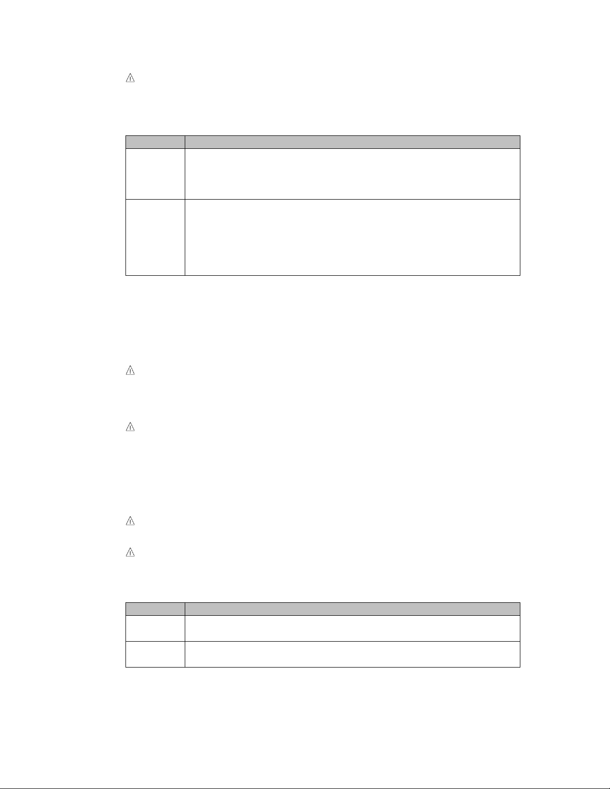
STEP
ACTION
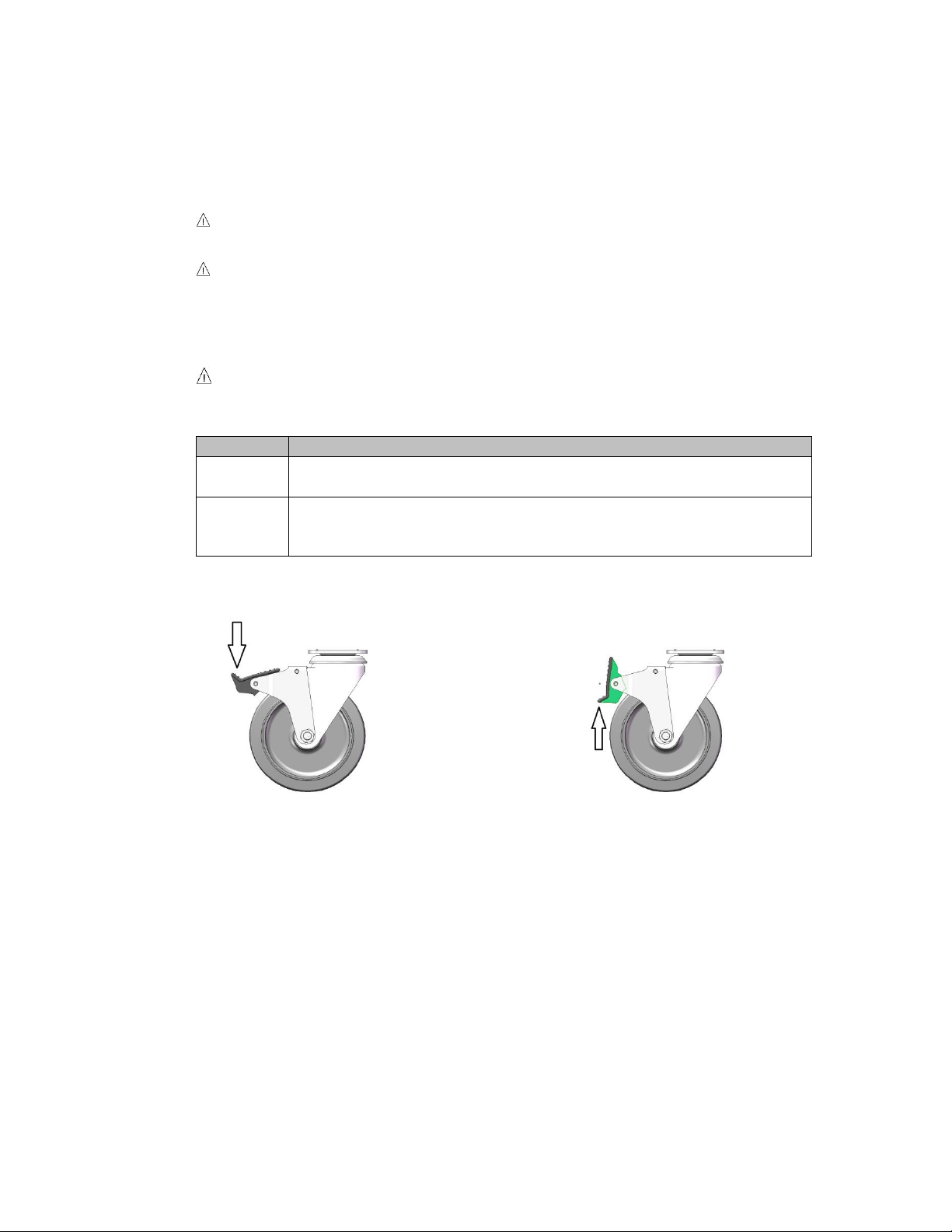
1
To lock the caster, step down on the outermost edge of the locking
tab located at the top of the caster wheel. (See Figure 4)
2
To unlock the caster step down on the top, innermost edge of the
locking tab OR lift up on the outermost edge of the tab. (See
Figure 5)
Figure 4
Figure 5

UltraScan™ Table
Page 13 of 36 14512-L
DCR-00335
Single Pedal Brake (optional)
The casters installed on your UltraScan™ Table with the optional Single Pedal
Break are total locking casters when in the locked position; the caster is
prevented from both rolling and swiveling. When in the neutral position, all
casters are free to roll and swivel. The last position is the steer position; with the
casters at the head end free to swivel and roll while the casters at the foot end
are free to roll but locked from swiveling.
WARNING, POTENTIAL FOR INJURY OR DEATH. To reduce the risk of
a potential fall, lock all casters before using equipment.
WARNING, POTENTIAL FOR INJURY OR DEATH. Once the table and
patient have been properly positioned, ensure the casters are locked
and the Hand Wand is placed in a safe position to prevent incidental
contact and unwanted movement of the table surface during the
procedure.
STEP
ACTION
1
To lock the casters, step down on pedal labeled lock on either side
of the table. (See Figure 6)
2
To unlock the casters and obtain the neutral position, step down
on the raised pedal on either side of the table until the pedals are
level.
3
To utilize the steer function, step down on the pedal labeled steer
on either side of the table.
Figure 6
Lock
Steer
UltraScan™ Table
Page 14 of 36 14512-L
DCR-00335
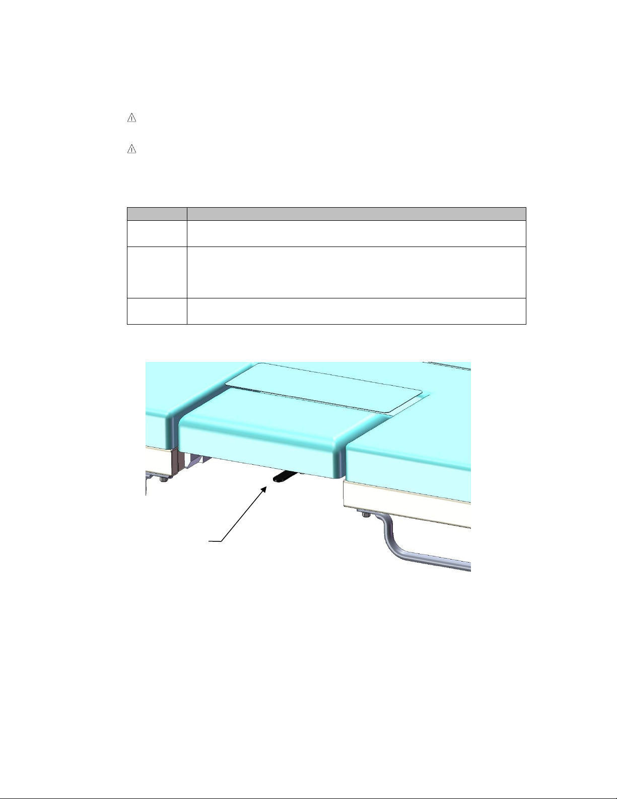
Drop Sections (on select models)
The drop section is designed to be opened or closed easily with one hand.
WARNING, POTENTIAL FOR INJURY. Avoid placing your hand in or
near the drop section mechanism during operation
WARNING, POTENTIAL FOR INJURY OR DEATH. After closing, always
lift up on the drop section to assure that is totally locked before patient
entry or exit.
STEP
ACTION
1
To open the drop section, locate the metal handle mounted on the
bottom of the drop section at the front edge. (See Figure 7)
2
Pulling the handle outward, from under the drop section, will
release the latch mechanism and allow the drop section to swing
open. Do not abruptly yank or jerk on handle, it is designed to work
with a smooth, steady pull
3
To close the drop section lift the drop section smoothly until it is
securely in the full, upright and locked position.
Figure 7
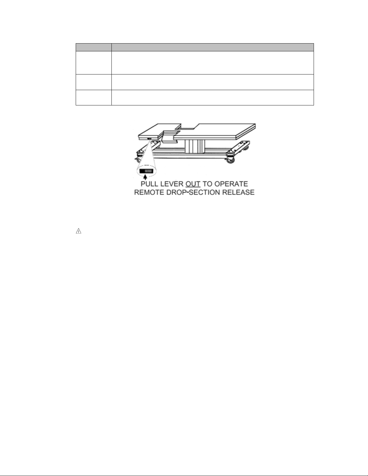
Additional the drop section on the patients left (imagining drop section) can be
opened remotely from the left side of the table.
Release Lever
UltraScan™ Table
Page 15 of 36 14512-L
DCR-00335
STEP
ACTION
1
To open the imagining drop section remotely, locate the remote
release on the patient’s right side just next to the left side drop
section on the side toward the head of the table. (See Figure 8)
2
Pulling the handle outward will release the latch mechanism and
allow the drop section to swing open.
3
To close the drop section lift the drop section smoothly until it is
securely in the full, upright and locked position.
Figure 8
CAUTION, PRODUCT DAMAGE MAY RESULT. It is not necessary to
"slam" the drop section closed. Slamming the drop section closed will
startle the patient and may result in damage to the mechanism.

UltraScan™ Table
Page 16 of 36 14512-L
DCR-00335
Back Rest (on select models)
Select models of the UltraScan™ Table that have drop sections also has a
convenient patient support back rest on the patient’s right side. The back rest is
part of a multi-functional feature that also operates as a drop section.
WARNING, POTENTIAL FOR INJURY. Failure to hold the back rest
when the lever release lever will result in the back rest lowering
suddenly, possibly causing injury to the patient.
STEP
ACTION
1
To raise, lift up on the outside edge of the back rest (drop section
on the patient right) until the locking pin engages and holds the
back rest in the elevated position.
2
To lower, grasp the top edge of the back rest and exert a little
pressure towards the center of the table and pulling the drop
section release handle (See Figure 7) will release the latch
mechanism Lower the back rest to the flat position.
UltraScan™ Table
Page 17 of 36 14512-L
DCR-00335
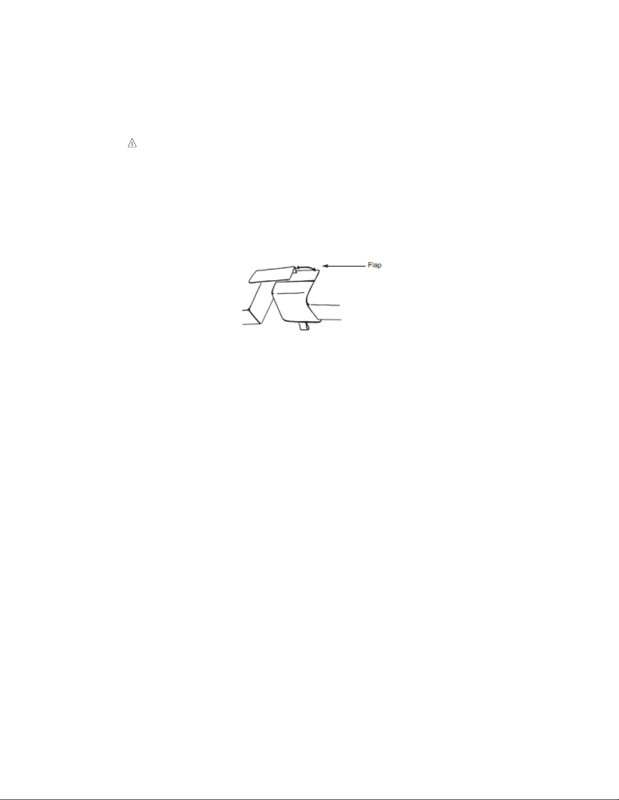
Non-Pinch Closure (on select models)
The non-pinch closure flap located at the back edge of the back rest is designed
to reduce the possibility of the patient being pinched when the back rest is raised
or lowered.
WARNING, POTENTIAL FOR INJURY. Do not operate drop section or
back rest if non-pinch closure flap is absent. The flap is attached to the
bed with hook and loop tape and can easily be adjusted whenever
necessary.
Examine the non-pinch closure flap with the back rest raised and lowered and
when the arm rest is open and closed. The flap attaches to the bed surface with
hook and loop tape that has been permanently attached to the surface. (See
Figure 9)
Figure 9
Occasionally the flap may become bent or creased. When that occurs, remove
the flap from the bed surface by separating the hook and loop strips. (See Figure
6) Next, return the flap back to original shape by bending it farther in the
opposite direction of the bend or crease and allowing it to spring back to flat.
Should the flap require replacement, you may order one through Medical
Positioning, Inc. at 1-800-593-ECHO (3246).

UltraScan™ Table
Page 18 of 36 14512-L
DCR-00335
Manually Operated/Removable Foot-Drop Section
The UltraScan™ is provided with a foot drop section that is designed to
comfortably and safely support the patient’s legs at times when the foot stirrups
are not used. The Ultra DBI™ is provided with a retractable Patient Foot Rest to
assist the patient in resting their feet when in the upright, seated position. The
patient’s feet should be placed on the metal strip on the front of the Foot Rest.
WARNING, POTENTIAL FOR INJURY OR DEATH. The foot drop section
is designed to support more weight than a patient’s legs alone, but it is
a collapsible and/or removable section and is not designed to support
full patient body weight. Never allow the patient to apply full body
weight to the extended foot drop section portion of the table while
entering or exiting the table as this may result in instability of the table.
Have the patient enter and exit the table from the side or from the foot
end with the foot section collapsed.
WARNING, POTENTIAL FOR INJURY OR DEATH. Verify both sides of
the foot drop section’s hinges have the pivot locks engaged when
raising the foot section. Failure to have both pivot locks engaged can
result in sudden lowering of the foot drop section.
WARNING, POTENTIAL FOR INJURY. Keep hands clear of the foot
section hinges during operation.
WARNING POTIENTIAL FOR INJURY. Periodically check both sides of
the foot drop section’s hinges to make sure they are between the
receivers mounted on both sides of the table’s frame.
Foot Drop Section Operation
STEP
ACTION
1
To lower the foot drop section, slightly lift the foot end of the foot
drop section and pull back approximately 1 inch. Carefully lower
the foot drop section until it is in a vertical position.
2
To raise the food drop section, grasp the foot drop section near the
bottom and swing it up to ta position slightly above horizontal.
While in this position, push the foot drop section in to engage the
pivot locks.
UltraScan™ Table
Page 19 of 36 14512-L
DCR-00335
WARNING, POTENTIAL FOR INJURY. Use care to firmly hold the
removed foot drop section. Failure to hold the foot drop section could
result in dropping the foot drop section.
Foot Drop Section Removal/Installation
STEP
ACTION
1
Begin by placing the foot drop section in the lowered position.
Grasp the foot drop section on the sides and lift straight up. Use
caution to not drop the foot drop section when removing from the
table.
2
Grasp the foot drop section on the sides and hold it vertical with
the pivot brackets pointing up. While in this position, carefully
place the foot drop section’s pivot brackets between the receivers
mounted to the sides of the table frame and allow the foot drop
section to hang in a vertical position. Raise the foot drop section
following the raising instructions above.
Foot Board (on select models)
The UltraScan™ is equipped with a foot board that can be opened for use in
extreme reverse Trendelenburg (foot end down) positions and when the foot drop
section is lowered as a foot rest.
WARNING, POTENTIAL FOR INJURY OR DEATH. Always raise the foot
board when in reverse Trendelenburg (foot end down) positions greater
than 15°. Failure to raise the foot board may result in the patient sliding
off the table surface.
WARNING, POTENTIAL FOR INJURY OR DEATH. The foot board is
designed to support more weight than a patient’s legs alone, but it is a
collapsible a section and is not designed to support full patient body
weight. Never allow the patient to apply full body weight to the
extended foot board while entering or exiting the table as this may
result in instability of the table. Have the patient enter and exit the table
from the side or from the foot end with the foot section collapsed.
WARNING, POTENTIAL FOR INJURY. Keep hands clear of the foot
board hinges during operation.
WARNING, POTIENTIAL FOR INJURY. The foot board is collapsible and
thus care should be taken when lowering the foot board to avoid
closing on the patient’s feet and/or legs.
STEP
ACTION
1
To raise the foot board, grasp the end toward the head of the table
and rotate up and toward the foot of the table.
2
To lower the foot board, grasp the end and rotate down and
toward the head of the table.

UltraScan™ Table
Page 20 of 36 14512-L
DCR-00335
Foot Stirrups
The foot stirrups are conveniently stored on the underside of the seat section of
the UltraScan™ when not in use. When needed, they are horizontally adjustable
and will lock in place anywhere along the travel of the support pars.
WARNING, POTENTIAL FOR INJURY OR DEATH. The foot stirrup is
designed to support more weight than a patient’s legs alone, yet is not
designed to support full patient body weight. Never allow the patient to
apply full body weight to the foot stirrup.
Foot Stirrup Operation
STEP
ACTION
1
To extend the foot stirrups from the storage position, grasp the
end, push down and pull out toward the foot end of the table.
Rotate the stirrup
2
Rotate the stirrup to the upright position.
3
Repeat the steps 1 and 2 for the other side.
4
The foot stirrups can adjust laterally and in length as desired. The
assembly uses a frictional lock to hold in place once weight is
applied by placing the patient’s foot in the stirrup.
Foot Stirrup Storage
STEP
ACTION
1
Rotate the stirrup toward the head end of the table and into the
storage position.
2
Grasping the end of the foot stirrup, slide the assembly under the
seat section of the table by pushing it toward the head end of the
table.
Removable Collection Tray (on select models)
The removable collection tray is included on UltraScan™ Tables equipped with
the posterior cut-out. The tray is easily removable and replaced when the foot
drop section has been removed from the table. The tray may be cleaned
according to your institutional policies.
Table of contents
Other MPI Medical Equipment manuals


