Bench Dog Tools ProCabinet 40-110 User manual

ProCabinet™
Stock No. 40-110
INSTRUCTIONS
Congratulations on your Bench Dog
ProCabinet purchase! Follow these
simple assembly instructions and you’ll
be ready to support the heaviest router
tops on the market.
Note: Please read these instructions
completely before starting to assemble your
ProCabinet. Familiarity with the process will
make the steps easier to understand. Please
follow all steps carefully.
(28331)
RTD10000609AA
2
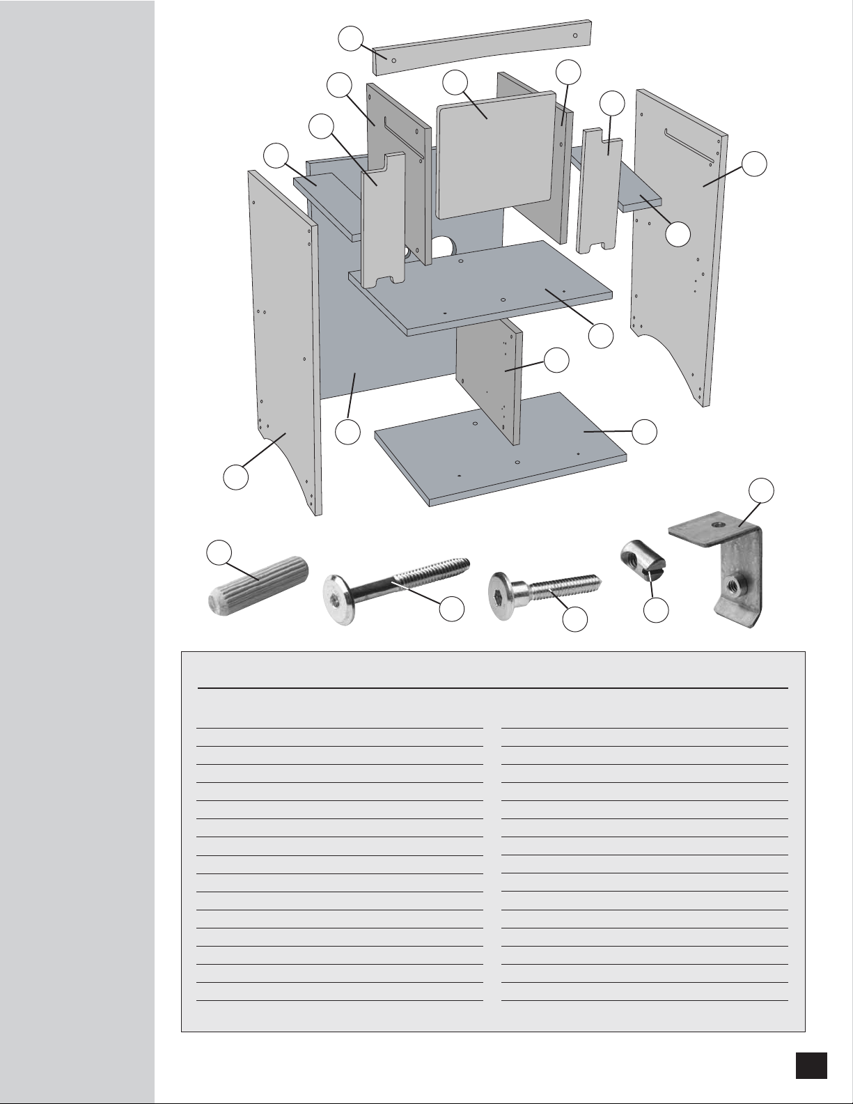
1 Shelf 1
2 Drawer Divider 1
3 Bottom 1
4 Left Side Panel 1
5 Right Side Panel 1
6 Back Panel 1
7 Bit Divider Left 1
8 Bit Divider Right 1
9 Header 1
10 Bit Storage Shelf 2
11 Door 1
12 Bit Storage Covers 2
13 Round head bolts, 1/4-20 x 2" 32
14 Phillips Pan Head Screw #6 x 1/2" (Not Shown) 4
15 Phillips Pan Head Screw #8 x 11⁄2"(Not Shown) 6
16 Phillips Pan Head Screw #6 x 3/4" (Not Shown) 8
17 Hex Wrench, 5/32" (Not Shown) 1
PARTS LIST
Quantity Quantity
18 Hex Wrench, 3/16" (Not Shown) 1
19 1/4-20 Cross Dowels 32
20 Thread Lock (Not Shown) 1
21 Decal (Not Shown) 1
22 Washers (Not Shown) 2
23 Brushed Nickel handle (Not Shown) 2
24 Wood Dowel 11
25 Guide Rail (Not Shown) 4
26 Dust Port (Not Shown) 1
27 Hinge (Not Shown) 2
28 Hinge Baseplate (Not Shown) 2
29 Shoulder Bolts, 1/4-20 x 40mm 4
30 Nylon Spring Pins (Not Shown) 4
31 Storage Door Locks (Not Shown) 3
32 Leveler Brackets (Not Shown) 4
33 Leveler (Not Shown) 4
34 Table Mounting Brackets 4
EXPLODED VIEW
12
7
9
11
12
6
1
2
3
5
8
4
10
24
13 19
34
29
10

3
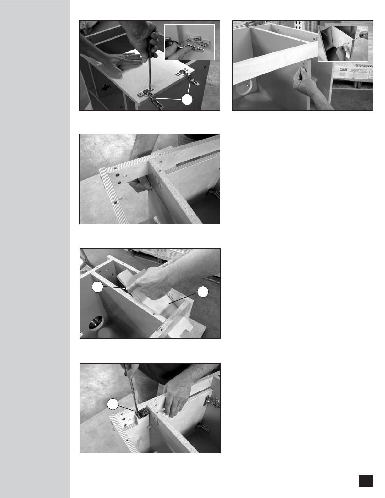
1. Attach the Drawer Divider (2) to the Shelf (1),
as shown in Fig. 1. Use two 1/4-20 x 2"
round-head bolts (13) and two steel
cross-dowels (19). Place a dab of thread-lock
on the end of the bolts and tighten using the
supplied 4mm Hex Wrench. Always install the
cross dowels before the bolts.
2. Follow the same procedure used in Step 1 to
attach the Drawer Divider (2) to the Bottom
(3), once again using two 1/4-20 x 2"
round-head bolts (13) and two steel cross
dowels (19). Fig. 2.
3. Install eight wood dowels (24) into the Shelf (1)
and Bottom (3), as shown in Fig. 3. Do not
glue the dowels, they are for alignment
purposes only. Be sure to place them in the
correct holes, which have a single hole drilled
through the end of the panel. The other holes
in the panels are double-drilled for use with the
bolt and steel cross dowels. These
double-drilled holes have two holes that
intersect, one through the top or bottom of
the panel, and the other through the end of
the panel.
4. Place the shelf assembly onto the Left Side
Panel (4), as shown in Fig. 4.
5. Place the Right Side Panel (5) onto the shelf
assembly. This panel is marked "R" on the
inside. Be sure to fit the dowels into their
proper holes.
6. Bolt the Right Side Panel (5) to the shelf
assembly using four 1/4-20 x 2" round-head
bolts (13) and four steel cross dowels (19).
Install the cross dowels first. Use the 4mm
hex wrench to lightly tighten the bolts. You
will fully tighten the bolts after the cabinet is
fully assembled. Fig. 5.
7. Follow the same procedure to bolt the Left
Side Panel (4) to the shelf assembly.
Fig. 1 Fig. 2
Fig. 3
Fig. 4
Fig. 5
CABINET ASSEMBLY
1
2
2
1
3
2
3
1
4
5

4
8. Place the Back Panel (6) onto the cabinet.
Note the orientation of the dust port and
cord cut-outs in Fig. 6. All steel cross-dowel
holes are located inside the cabinet. Use ten
1/4-20 x 2" round head bolts (13) and ten
steel cross dowels (19) to secure the panel.
Note: Some of the cross dowels will be
easier to install by positioning the cabinet
upside down.
9. Install a Guide Rail (25) to the Left and
Right Side Panels (4 & 5), using four #6 x 3/4"
flat head screws (16). These white nylon guide
rails are used for holding the pull-out router bit
storage trays.
Note: Position the flat and straight side of
the guide rail up. Also, there is a left and
right orientation.
10. Install Guide Rails (25) to the Router Bit
Storage Divider Panels (7 & 8), using four
#6 x 3/4" flat head screws (16). Begin by laying
out the panels, as shown in Fig. 7. Make sure
the "L" and "R" markings are right-side-up.
Note: There are left and right rails. Be sure
the flat side of the rail is "up".
11. Install the Left and Right Bit Divider Panels
(7 & 8), as shown in Fig. 8. The divider
panel marked "R" opposes the right side
panel marked "R", and the divider panel
marked "L" opposes the left side panel
marked "L". Use six 1/4-20 x 2" bolts (13)
and six steel cross dowels (19).
12. Install two Wood Dowels (24) into the front
of the divider panels, do not glue the dowels.
13. Attach the Header (9) to the cabinet with
four 1/4-20 x 2" bolts (13) and four cross
dowels (19). Fig. 9.
14. Attach the center-door Hinge Baseplates (28) to
the cabinet as shown in Fig. 10. The plate
resembles a cross. Position the top of the cross
nearest the front edge of the cabinet. The
release tab points to the back panel.
CABINET ASSEMBLY
Fig. 6 Fig. 7
Fig. 8
Fig. 9
Fig. 10
68
7
25
9
28
5
15. Install the two Hinges (27) by pressing the
cups into the pockets in the Door (11), and
turning the integral cam fasteners. Fig. 11.
Do not overtighten the cam.
16. Clip the Door (11) onto the cabinet.
Fig. 11 inset.
17. Install the center-door stop dowel by
placing one wood dowel (24) and a dab of
woodworking glue into the lower hole, as
shown in Fig. 12.
18. Install the Door Handle (23) using the
included hardware. Fig. 12 inset.
19. Install four Wood Dowels (24) into the
cabinet, as shown in Fig. 13. Place a dab of
woodworking glue on the dowels to keep
them in place. These dowels will support the
router bit storage covers.
20. Press the four Nylon Spring Pins (30) into the
router bit storage covers using a flat surface.
Note: When pins are fully depressed, they
will be flush with the surrounding surface.
The pins will stand proud of the surrounding
surface when not depressed.
21. Install the two Bit Storage Covers (12) onto
the cabinet, as shown in Fig 14. Note the
left and right orientation of the doors. You
will have to depress the spring pins and
align them with the routed grooves. The
covers will snap into the routed grooves in
the surrounding panels. Be sure to first
place the covers above the two wooden
dowels. If you must remove the covers from
the cabinet, first slide the covers all the way
back on grooves, then push up at the rear
and lift away.
22. Install two Storage Door Locks (31), as
shown in Fig. 15.
Note: If you need to adjust the tension,
gently pry apart the clip with a flat-head
screwdriver, as shown.
CABINET ASSEMBLY
Fig. 11 Fig. 12
Fig. 13
Fig. 14
Fig. 15
27
12
30
31
6
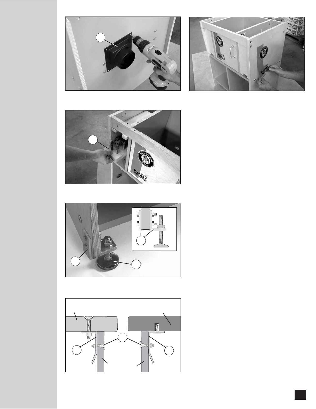
23. Install the Dust Port (25) as shown in Fig. 16.
Use four #6 x 1/2" pan head screws (13). Begin
by drilling four 3/32" pilot holes through the
port at the four corners. No pilot holes are
necessary in the cabinet.
24. Install the three Decals (20) as shown in
Fig. 17. Immediately peel away the decal if
repositioning is necessary.
25. Your cabinet comes with two Bit Storage
Shelves (10). You must drill your own
bit-holding holes. Use a drill bit slightly larger
than the diameter of your router bit's shank.
26. Your shelves slide into the cabinet, as shown in
Fig. 18. Your cabinet accepts up to four Bit
Storage Shelves.
27. Attach the two-piece Leveler/Caster Brackets to
the cabinet’s Side Panels as shown in Fig. 19.
Use two 1/4-20 Hex Bolts per bracket.
28. Mount the Leveling Feet to the Brackets as
shown in Fig. 19. For added versatility,
use Bench Dog’s ProCasters instead
(sold separately).
Mounting a Tabletop
1. Attach the four Table-Mounting Brackets (34)
to your tabletop, as shown in Fig. 20. Use the
hardware provided with your tabletop.
2. Position the tabletop in place on the ProCabinet
and attach the tabletop by putting the
1/4-20 x 40mm Shoulder Bolts (29) bolts
through the Header (9) and the Back Panel (6).
CABINET ASSEMBLY
Fig. 16 Fig. 17
Fig. 18
Fig. 19
Fig. 20
ProTop
Tabletop
ProMaxRT
Tabletop
ProCabinet
Sides
34
34
25
33
32
32
10
29

Rev 09/08
© 2008 Bench Dog Tools
7
WARRANTY & SAFETY
Important Safety Points
Before operating your router table please read this manual thoroughly. Safety and use tips are contained in
the manual. This page is not the sole source of safety information. Retain the manual for future reference.
Refer to your router owner's manual for safety instructions regarding use of that tool. This manual is not an
instruction book on how to do woodworking with a power tool. We encourage all woodworkers to continually
seek improvement in their woodworking skills, regardless of their craftsmanship or years of experience. The
router table, fence and accessories must only be used for their intended purpose: woodworking via normal
routing operations. “Normal operations” means basic shaping of wood in conditions where grounded electricity,
sharp tools, dust, and rapidly spinning parts can be used or encountered safely. The following instructions
elaborate on this concept.
1. Do not use your router table as a step or seat.
2. The top and cabinet must be properly secured, and must be level before use. Inspect your table and base for
damage and levelness prior to each use.
3. Keep work area clean, dry and well lit.
4. The hardware affixing the insert to the routertop must be installed for safe use. Tighten insert hold-down
screws before each use.
5. Safe operation requires a router table fence, bit guard, dust collection system, starting pin or fulcrum, and
speed reducer for large diameter bits. We recommend reducing router speed for 1" or larger diameter bits.
Consult your bit manufacturer for the exact speed.
6. Use the right tool for the job. Do not force a tool or attachment to do a job for which it was not designed.
7. Secure your work with a featherboard, clamps, or a vice when appropriate. The use of inappropriate
accessories may cause injury.
8. Wear safety glasses, dust mask, face shield and ear protection. This is not an exhaustive list. Every-day eye
glasses do not substitute for safety glasses.
9. Do not wear gloves or jewelry while using a power tool and ProMAX
10. Maintain your equipment and its accessories in good working condition. Look for wear, poor alignment of
moving parts, binding of moving parts, breakage, poor mounting, or other conditions that may affect
operation and safety. Repair or replace any damaged parts.
11. Disconnect the power before moving, adjusting, or repairing parts, or otherwise maintaining your router table
and any accessories you may be using.
12. Keep children, pets, and those who may disregard safety away from work area, cords, sockets and tools.
13. Wear snug fitting clothes and keep long hair back to avoid catching in moving parts.
14. Do not overreach. Maintain balanced footing and stance.
15. Stay alert. Use common sense.
LIMITED TWO-YEAR WARRANTY
We make every effort to assure that our products meet quality and durability standards, and warrant to the
original retail purchaser that this product is free from defects in materials and workmanship for two years. Remedy
shall be limited to Bench Dog’s choice of repair, replacement or refund. This warranty does not provide remedy
for consequential economic loss.
This is a limited two-year warranty. It requires the purchaser to contact Bench Dog in writing within 30 days of
discovering the defect. Warranty does not apply to defects due directly or indirectly to misuse, abuse, negligence
or accidents, repairs or alterations, or due to lack of maintenance. It excludes components and parts not
manufactured by Bench Dog, defects caused by failure to provide a suitable installation environment, and damage
caused by use for purposes other than those for which the product was designed. Bench Dog, Inc. reserves the
right to make product changes without notice and without obligation to make these changes on products
previously sold. It excludes warranties of fitness for a particular purpose.
If the product is defective, we reserve the right to fix it, replace it, or refund the cost of the product to you.
Typically, this results in a refund. All claims are limited to the two-year claims period. We must receive the product
before a credit or refund will be issued. The warranty language on the product or in the product’s manual may
contain additional limitations, which govern.
If you wish to return something, call the dealer where you purchased the product. If you wish to return something
purchased from Bench Dog directly, call 1-800-786-8902 to receive an RMA number. Upon receipt and inspection of
the goods, a credit or replacement will be issued for defective products. Return of nondefective items to Bench
Dog are subject to a 7% restocking charge. This is necessary due to the cost of checking, repackaging, and
inventorying the stock.
BENCH DOG DISCLAIMS AND BUYER EXPRESSLY WAIVES ANY AND ALL WARRANTIES, EXPRESS OR
IMPLIED, INCLUDING BUT NOT LIMITED TO, IMPLIED CONDITIONS OF FITNESS FOR A PARTICULAR
PURPOSE, MERCHANTABILITY, OR ANY OTHER MATTER.
Table of contents


