ELME 586TB User manual

MANUAL
Servicebox 586TB / 588TB
INNOVATION

Thank you for purchasing
this Servicebox to your
586TB / 588TB!
This guide provides the informaon needed to service and maintain
your spreader. A spreader used and serviced properly retain their
qualies for a long and protable life in service, and you get the full
advantage of all the features.
Maintenance may only be carried out by qualied personnel.
For more detailed informaon about spare parts and service
instrucons, we refer to our manual for the specic spreader.
All informaon, illustraons and specicaons in this manual are based on the latest informaon
at the me of publicaon. The right is reserved to make changes at any me without noce.
COPYRIGHT© 2021 ELME Spreader AB.
Index
Twistlock Assembly 3-5
Wear pads & Shims 6-8
Flextrack Chain 9
Back up Parts 10-13
Summary of all parts included 14
Why use Genuine Parts? 15

The twistlock is a genuine ELME part, which is cered and marked with a unique
serial number.
TWISTLOCK ASSEMBLY
3

4
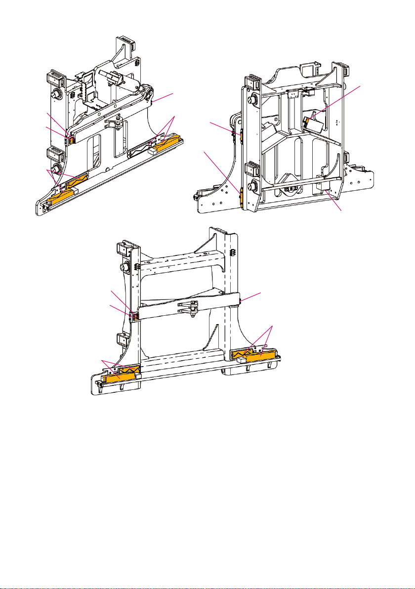
To remove the twistlock and sleeve, proceed as follows:
1 Remove the cover (item 23).
2 Remove the sensor bracket (item 1), by loosening and remove the two bolts
(item 2).
3 Loosen and remove the two screw allens (item 3).
4 Remove the seated bracket assembly. This assembly includes nut, indicator,
springs, bracket and e rod (item 4).
111
2
12 12
5
8
9
10
7
21
12
13
14
20
18
19
15
16
17
4
3
4
65
22
23

5 Loosen and remove the screw allen (item 5). Then remove the seated pin (item 6).
6 To give space, remove the two sensors (including hose clamps/brackets) by
loosening and removing the bolts and the washers (item 7).
7 Remove the bolt (item 8), the washer (item 9) and the lock washer (item 10).
Turn the twistlock cylinder away (item 11), to give space.
8 Remove the four bolts and washers (item 12) from the crank (item 13).
9 Li o the crank and remove the sleeve (item 14), the key (item 15) and the roll
pin (item 16) aached to the twistlock (item 17).
10 Remove the twistlock (item 17).
11 Finally, loosen and remove the bolts and the washers (item 18) from the twistlock
sleeve (item 19) and remove it.
Inspection/greasing prior to reassembly
12 Aer removal of all twistlock parts, remove all grease and dirt from the parts and
also from the corner of the head. Steam clean or clean with some form of solvent.
13 Check the twistlock (item 17) for wear on the head. The sleeve (item 14) and the
crank (item 13) should also be inspected for possible wear or damage and
replaced if necessary.
It should be noted that the state of the sleeve (item 14) and the recess in the
twistlock (item 17) is very important, as these parts are carrying the load when
acontainerislied.
14 Before reassembling the twist lock parts, it is very important to plenful grease
the bushing inside the twist lock sleeve (item 19), the spacer (item 20) and the
surface it is placed on. Also grease the head of the twistlock (item 17) and inside
the tower (item 22) before mounng the seated pin (item 6).
15 It is also very important to plenful grease the surface both on top of and
underneath the area as shown on the gure on page 4 (item 21) before
reassembling.
Replacing / Fitting twistlocks
16 Replace/reassemble in reverse order, see above (from point 10 and backwards)
5

To eliminate mechanical fricon, there are plasc pads between extension beams and
main frame. The pads are posioned for support to reduce and also to absorb horizon-
tal and vercal shock loads, they are mounted in several retainers. This design makes
inspecon and replacement easy. There are also plasc pads on the carriage and the
PPS frame (opon), see next two pages.
WEAR PADS & SHIMS
6
Plastic wear pads
The plasc wear pads (item 1) should be inspected for wear. Replacing the wear pads
can be done with ordinary hand tools and without removing the beams. The wear
pads (items 3) are not likely to wear and are therefore not included in the service
box.
Shims
If the play on the sides of the extension beam is more than 10 mm, it is possible to
use dierent sizes of shims (item 2) to reduce the play. Always check the play in 30
posion or where the extension beam is the greatest. Minimum play should be 1 mm
aer shimming.
7
1
1
1,2
1,2
1
1
33
3
3
1,2
1
1
1,2
PPS
MPS

8
Plastic wear pads
The plasc wear pads (item 1) should be inspected for wear. Replacing the wear pads
can be done with ordinary hand tools and without removing the beams. The wear
pads (items 3) are not likely to wear and are therefore not included in the service
box.
Shims
If the play on the sides of the extension beam is more than 10 mm, it is possible to
use dierent sizes of shims (item 2) to reduce the play. Always check the play in 30
posion or where the extension beam is the greatest. Minimum play should be 1 mm
aer shimming.
1
1
3
1
1
1
3
1
3
FRONT
FRONT
2
1
1
1
1
1

9
Included in this service box are complete extrack chains. On this page, you will nd
instrucons how to replace them.
FLEXTRACK CHAIN
Remove the extrack chain (item 1) by rst opening all links on it.
IMPORTANT! Carefully open each link with a suitable screwdriver or similar.
When all links are opened, unscrew the bolts (item 2), the washers (item 3) and
the nuts (item 4) on the brackets mounted in each end of the extrack chain
(item 1).
Remove the extrack chain. Replace with the new chain, by mounng it in reverse
order.
1
1
3
2Removable links
2
3
4
3
Removable links
Flextrack chain on carriage
1,2,3
10
BACK UP PARTS
A number of back up parts are also included in this servicebox, in case of breakdown.
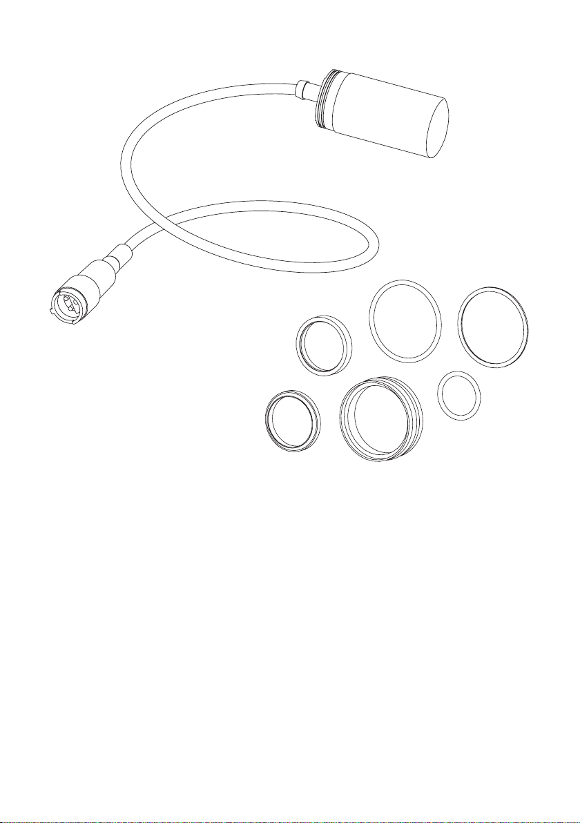
Proximity switch
For replacement of proximity switch / sensor in hook assembly.
Seal kits
For replacement of seal kits in extension, sideshi, lt and side clamp cylinders.
A seal kit for replacement in electro valve is also included in this servicebox.

Seal replacement - Sideshift cylinder and Tilt cylinder (PPS option)
Remove the side shi cylinder or e up the cylinder when working on the spreader.
Loosen gland (item 3) and hydraulic hoses and pull out the piston rod (item 1).
Be careful not to damage the piston rod when removing and beware of the oil spill.
Remove the nut (item 5), the piston (item 4) and the gland (item 3) from the piston
rod. Check the piston rod and cylinder for damages that can cause leakage and repair
or replace when necessary.
Carefully remove the seals (items 2), do not damage the surfaces. Clean all parts.
Place the new seals with oil or grease. Place the gland and the piston on the piston
rod, ghten the nut and secure it with the roll pin. Slide the piston rod assy. into the
cylinder and ghten the gland.
1
2
32
4
2
5
11

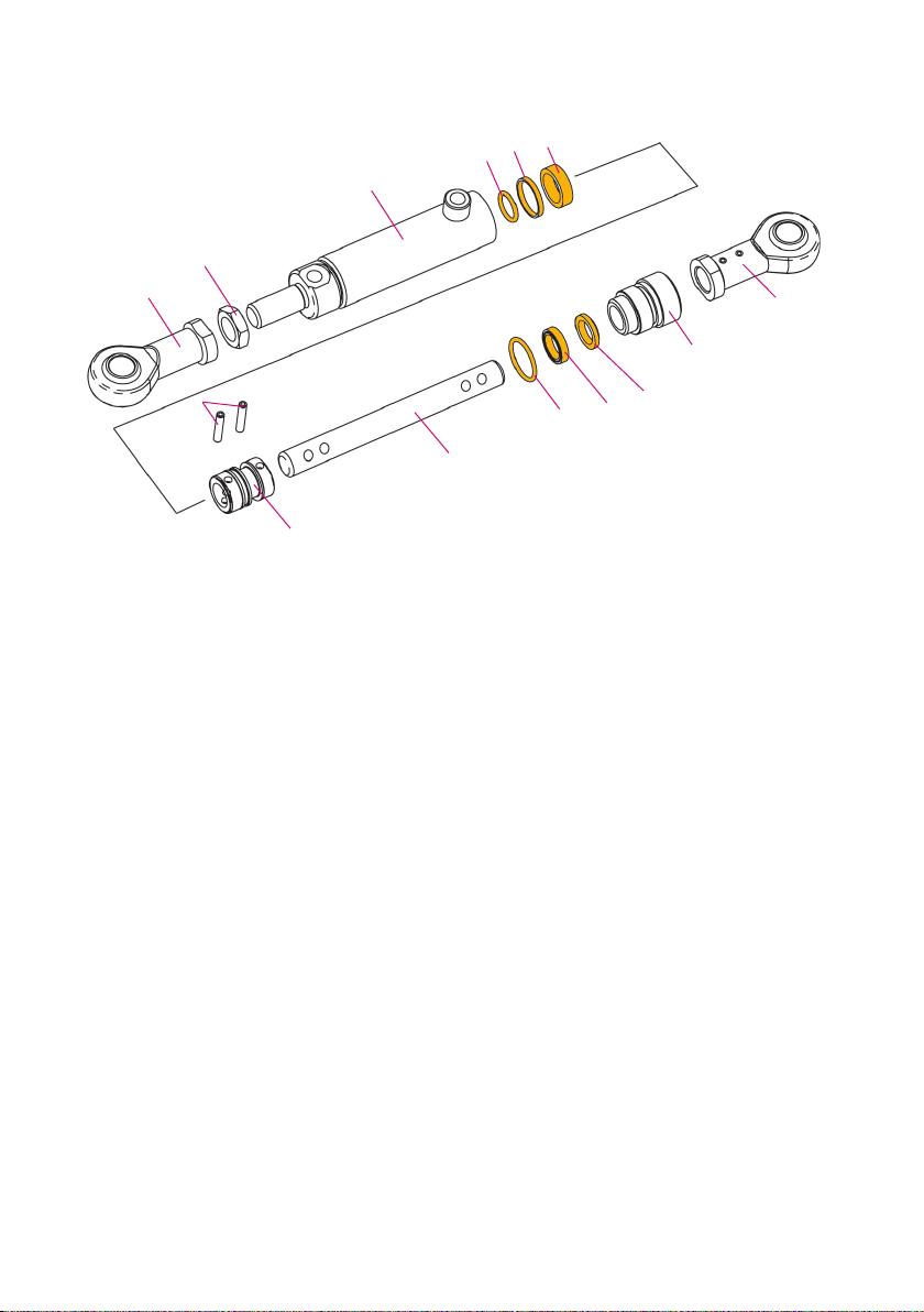
Seal replacement - Extension cylinder
Remove the extension cylinder from the spreader.
Loosen the 8 bolts (item 12) and pull out the piston rod. Be carefulnot to damage the
piston rod and beware of oil spill. (It is best if you aach a hose on the front oil
connecon of the cylinder and place the other end in a oil bin or a jerry can)
Remove the roll pin (item 2), the nut (item 3), the piston (item 4), the spacer
(item 5), the gland (item 7) and the washer (item 9) from the rod. Be sure that the
ring (item 10) stays on the painted part of the rod or take it o.
Check the piston rod and cylinder for damages that can cause leakage and repair or
replace when necessary.
Carefully remove the seals (items 1) from the piston, spacer, gland and washer, do
not damage the surfaces. Clean all parts. Place the new seals with oil or grease.
Place the washer, gland and the piston on the piston rod, ghten the nut and secure
it with the roll pin.
Slide the piston rod assembly into the cylinder and ghten the bolts (torque 23 Nm).
12
13
41
516
71891
10
11 12 13 15
14
16
17
18
19
2
Seal replacement - Twistlock cylinder
Loosen the gland (item 6) and pull out the piston rod (item 4), no need to loosen the
rod head. Use a dri punch to remove the roll pins (item 11) from the piston (item 2)
and remove the piston and the gland from the rod.
Carefully remove the seals (items 7, 3, 13, 5, 8 and 9), do not damage the surfaces.
Check the piston rod and cylinder for damages that can cause leakage and repair or
replace when necessary.
Clean all parts. Place the new seals with oil or grease. Place the gland and the piston
on the piston rod so that the securing holes line up and place the roll pins.
Slide the piston rod assembly in the cylinder and ghten the gland.
4
2
13
13
1
5
6
7
89
3
11
10
12
14

Summary of all parts included in the box:
Twistlock Assembly 1x Twistlock kit (Le)
1x Twistlock kit (Right)
2x Seated pin
2x Nut*
2x Compression spring*
2x Compression spring*
2x Tie rod*
2x Seated bracket*
2x Indicator*
Wear pads & Shims 4x Wear pad - Endbeam
30x Wear pad - Mainframe
6x Wear pad - Carriage
6x Shims - Mainframe
2x Shims 1 mm - Carriage
2x Shims 2 mm - Carriage
Flextrack Chain 2x Flex track chain - Extension
1x Flex track chain - Carriage
Back up Parts 2x Proximity switch
1x Seal kit - Sideshi cylinder
1x Seal kit - Extension cylinder
1x Seal kit - Twistlock cylinder
1x Seal kit - Electro valve
PPS (option) 6x Wear pads (carriage)
2x Shims 1 mm (carriage)
2x Shims 2 mm (carriage)
1x Seal kit - Tilt cylinder
* these parts are assembled.
14

ELME GENUINE PARTS
By using ELME genuine parts, you always get parts you can rely on and true peace of
mind. If you are using non-genuine parts, you put weak links into a strong, perfectly
designed chain of interacve components. Please note that non-genuine parts are made
by factories that have not been approved by ELME and they are oen manufactured to be
as cheap as possible, using inferior materials, workmanship and by reversed engineering.
Non-genuine parts are high risk. Real cost and real risk is measured not in the price, but in
the cost of the component in the event of failure. Use of non-genuine parts may lead to
higher downme and lower producvity due to more frequent failures. For correct operaon
of the spreader, only ELME Genuine Parts and accessories which are approved by ELME should
be used. If non-genuine parts are used, the warranty is not valid. By using ELME Genuine Parts
and accessories approved by ELME, you will maintain original standard. ELME will disclaim all
responsibility if parts from third party are used.
INSPECTION/MAINTENANCE
Always inspect your spreader before using it. If any kind of damage is detected – which may af-
fect the funcon of the spreader - this must be corrected before use. If the spreader needs to be
repaired, please contact a specialist and see to that only ELME Genuine Parts are used if need of
replacement. This is to ensure that the spreader sll is reliable. Repairs made by a non-qualied
person or use of non-genuine parts may lead to increased risk of personal injuries or damages.
Service and maintenance are necessary to keep capacity and eciency of the spreader for many
years.
MODIFICATION OF THE SPREADER/PRODUCT LIABILITY/WARRANTY
For the avoidance of doubt, ELME is not liable in case of damage due to factors beyond ELME’s
control or due to a lack of maintenance or the use of non-genuine parts. The spreader should
not be modied without consultaon with ELME. If so, this means that the spreader is not CE
approved and thus ELME has no product liability.
Why use Genuine Parts?
15

HEADOFFICE
ELME Spreader AB
Älmhult, Sweden
www.elme.com
SALES AND SPARE PARTS
ELME Spreader Trading (Shanghai) Co. Ltd
Shanghai, China
SPARE PARTS
ELME Americas Inc.
Marn, TN, United States
© ELME Spreader AB • 2021 Servicebok 586TB INN, 588TB INN Manual
This manual suits for next models
1
Table of contents
Other ELME Service Equipment manuals


