Benchcrafted Classic with Crisscross User manual

1
Package Contents:
Qty. Description
1 Hub
1 Flange
1 Main screw
1 Handle assembly (1 handle, 2
mushroom nuts)
1 Nut
1 3/16” x 1-1/4” groove pin
1 Acetal bushing
2 #12 x 1-1/2 round head wood
screw (for flange)
3 #9 x 1-1/2” round head wood
screw (for main nut)
3 #9 x 1-1/2” round head wood
screw (for acetal bushing)
1 spring plunger
2 leather washers
1 Crubber for lining insides of
vise jaws
The follwing included only if you
purchased a Classic w/ Crisscross.
2 Crisscross arms
1 pivot pin
3 snap rings (one extra)
2 8” mounting pins (Solo only)
2 2-1/2” mounting pins (Retro
only)
2 Mounting brackets (Retro
only)
4 5/16” x 1-1/4” cap screws
(Retro only)
2 1-3/4” steel bearing plates
2 #8 flat head wood screws
Installation Instructions
Copyright, Benchcrafted - Version Feb. 2018
www.benchcrafted.com

2
ATTENTION!
Read and understand these instructions COMPLETELY AND THOROUGHLY
before starting the installation or cutting into your bench.
We highly recommend that you NOT begin installation unless you have ALL
vise hardware in your possession.
Unpacking your vise:
Some parts are heavy. Be careful as you unpack and handle them. Also be aware that although we make
every effort to ease all edges, being cast and machined parts you may encounter a sharp egde or burr. If
you do, ease it with some fine abrasive paper or a fine file. Some components may have a rust preventa-
tive oil applied. You may want to remove this oil before installing the vise. Wipe it off with a paper towel.
This will leave a light film of oil on the parts that will help prevent rust and keep the parts moving smoothly.
You may find a slight excess of powder coating in the 3/8” holes in the Crisscross arms and Retro brack-
ets, making the mounting pins a little difficult to insert. Simply run a 3/8” twist bit, at slow speed in a hand
drill, through the holes to clear any excess coating.
Assembly
To assemble your vise you’ll need the hub, flange, main screw and the groove pin from the hardware kit.
You’ll need a small hammer and a 1/8” punch. If you don’t have a 1/8” punch, you can use a large nail set.
First slide the flange onto the shaft of the screw. The flat side faces the screw threads, since the concave
side mates with the back of the hub. Now insert the shaft into the hole in the hub. The fit is precise, so
don’t force it if you feel resistance, simply rotate the two parts in your hand, keeping them straight to each
other until they slide together. If it doesn’t go, look for burrs on the hub or screw. You can create a burr if
you hit the hub or screw against each other while unpacking the vise.
Look into the 3/16” cross hole in the hub and rotate the screw until you see it line up with the hole in the
shaft. Our current screws have two holes in the shaft (the hole closer to the screw threads is for our Glide
leg vise) it will be readily apparent that you’ll use the hole that’s closer to the end of the shaft since the
other one will be impossible to line up. Now insert the groove pin into the hub, smooth end first. It will slide
in freely until it contacts the shaft. If it doesn’t slide in freely use a 3/16” drill bit in a portable drill to ream
the hole. Variations the groove pin manufacturing process sometimes require this little step. Now rotate
the shaft slightly until the pin drops into the hole in the shaft. When the grooves in the end of the pin en-
counter the perimeter of the hub, begin tapping on the pin with your hammer until it begins to tighten up in
the hub. When tapping the pin into the hub, you should use a block of hardwood to raise up the hub so its
supported firmly under your hammer taps, instead of resting on the flange’s edge. Once the pin is tapped
nearly fully into the hub, use the punch or nail set to finish driving the pin into the hub. Tap the pin until its
centered in the hub. It’s very important that the pin be centered. If it’s not, you can shear the pin off with the
action of the vise.The vise is now assembled. The flange should spin freely on the shaft.

3
The Benchcrafted Classic Leg Vise
We developed the Classic Leg Vise for woodworkers who prefer the traditional look and function of
classic bench hardware from the 19th century and earlier. Unlike American examples, which use a T-
shaped casting and sliding wooden handle, we patterned our vise after extant French examples. The
classic look and function pairs excellently with the Benchcrafted Crisscross and maintains our ideal of
effortless workholding.
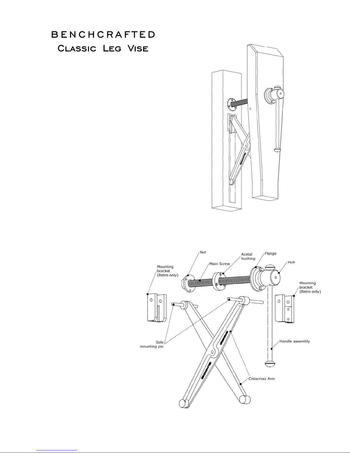
The Benchcrafted Crisscross
A popular mechanism for maintaining parallelism in vise jaws began to surface in the American patent
record in the mid 19th century. There are also documented sources of this mechanism in the La Forge
Royale catalog, Paris, late 19th to early 20th c. This device is basically two pieces or "arms" of metal or
wood, equal in length, joined in the middle to create a pivot. The upper ends of the arms (also on pivots)
are joined to the bench's leg and the chop. The resulting mechanism not only maintains a parallel open-
ing, but also supports the weight of itself, the vise screw, and the chop. The beauty of the mechanism is
its simplicity. In modern times this mechanism has become known as the "St. Peter's Cross", taken from
an early 20th c. publication describing it as such. To our knowledge, this is the only reference to this
device by name. There has been some discussion about the history of this moniker, and the possible
misnomer, since it was the Apostle Andrew that was crucified on an "X"-shaped cross, St. Peter being
crucified on a "T"-shaped cross, albeit upside down. We eventually acquired a 19th century version of the
St. Peter's Cross, and used it to prototype our version, the Benchcrafted Crisscross.
The Crisscross is built with a small amount of toe-in. In other words, the chop will contact the bench top at
the upper end of the vise slightly before it contacts the bottom. This helps hold thin or irregular stock. You
will need to follow the specific installation sequence in order to install the Crisscross to best effect.
About these instructions
We don't like to be wordy, and we don't like complexity. The length of these instructions is such as to
convey the information you need to install the vise intelligently. If it's superfluous, we won't include it, if its
useful for the installation, you bet we're going to include it. We know you don't want any surprises, and we
know this vise is going into some beautiful benches. This is the info you need to get it right straightway.
It's an easy install, but you can screw it up if you dive in without reading this.
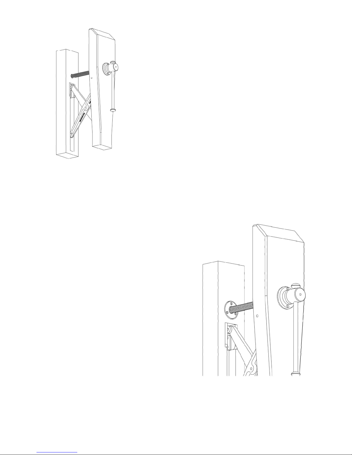
Illustrations are shown with a bench leg and chop only, without any joinery, for clarity.
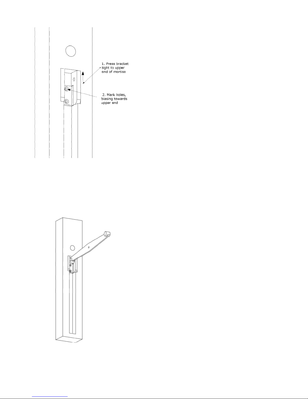
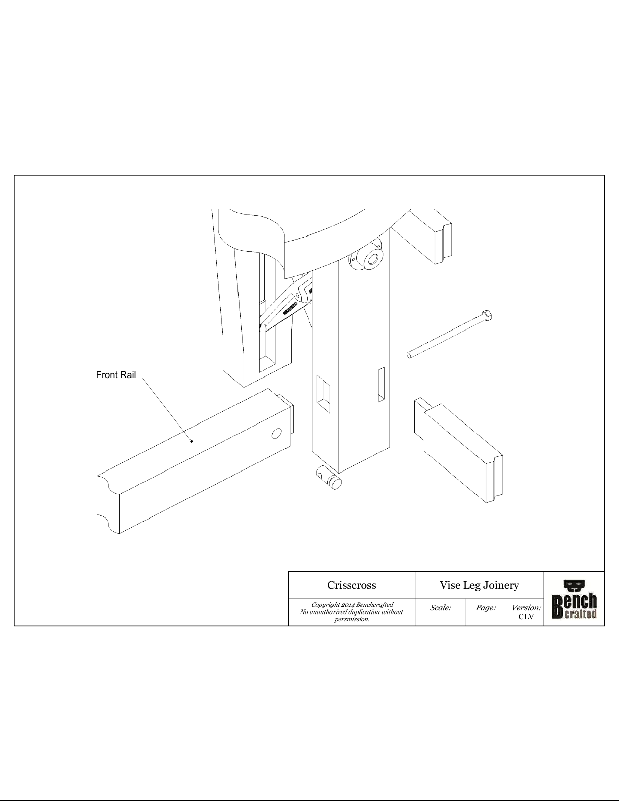
1. Layout
First you’ll layout and install the Crisscross, then once that’s done, you’ll attach the flange, nut and acetal
bushing of the Classic Leg Vise. It’s important to install the Crisscross first.
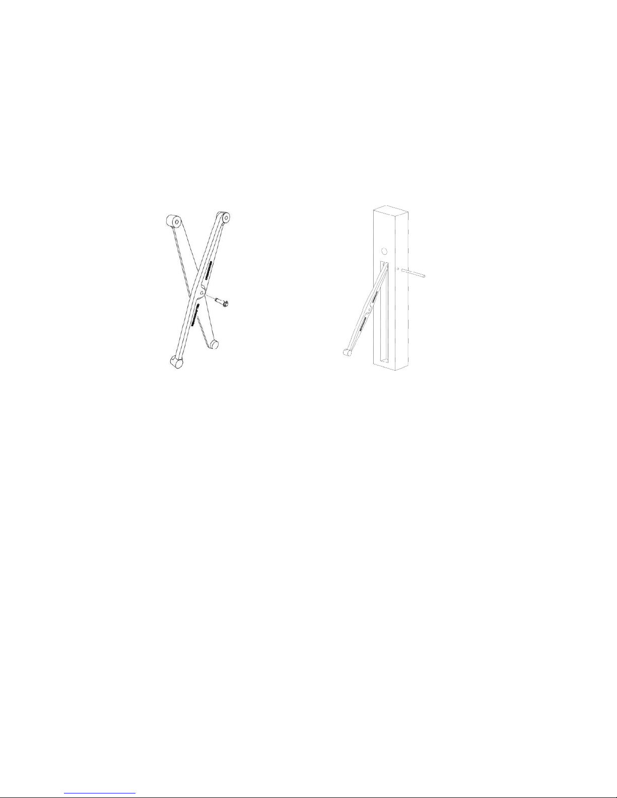
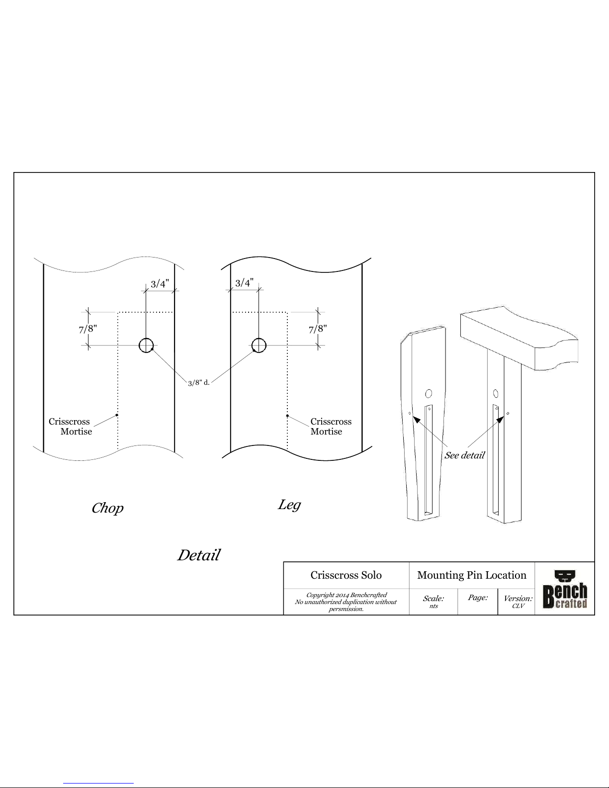
The Crisscross Solo and Retro occupies 19-1/2” of vertical space in your bench leg and chop. You can
position the Crisscross anywhere you like vertically (it should be centered left-to-right in the leg and chop)
even to the point of the mortise starting at the very bottom of the leg. If possible, try to keep some material
below the mortise (as pictured in the illustrations.) You should not mount the Crisscross Solo in a bench
leg that’s narrower than 3”, or the Retro in a leg narrower than 4”. Bench leg and chop each need to be at
least 2-1/2” thick. You don’t need solid stock, you can laminate 8/4 stock onto 4/4 stock to achieve that
thickness. Position the glue lines towards the inside face so the mortise floor falls within solid stock (not

4
on a glue line.) The chop can be as narrow as 5”, but you’ll get better holding if you make it around 8”
wide at the top. You can cut any design you like onto the sides of the chop--tombstone shape, coves and
curves-whatever. Just save that step for the very end.
To layout the Crisscross mortises, refer to the measured drawings at the end of these instructions. It is not
necessary for the Crisscross to be a specific distance below the vise screw. The location on the drawing
is simply a lowest ideal of both the Crisscross and vise screw together in a given bench height. You can
shift both the Crisscross and your vise screw locations up or down to suit your bench (Dimension “X”)
Layout everything in full size before you cut anything, especially if you’re installing this vise in an existing
bench. As an aid, we’ve included examples of how our Split Top Roubo bench joinery works with the
Crisscross.
There are four things to keep in mind when determining where to
vertically position your Crisscross:
1. The distance below the Crisscross: ideally, you don't want the mortise to be open at the bottom of
the leg. Best to keep some material here. Although if you have a wide and thick leg (5" or more) an open
mortise won’t pose any problems.
2. The distance between the top end of the Crisscross mortise and the vise screw: leave enough
material so the acetal bushing doesn’t intersect with the Crisscross mortise. Leave at least 1/4” between
the bottom of the acetal bushing’s counterbore and the top end of the Crisscross mortise. The drawing
shows the minimum.
3. Height of the bench: If you have a tallish bench, 36" or so, you might want to move everything up a
little. The drawings show, again, lowest ideal position. This makes for a lot of room above the screw (e.g.
holding wide boards) but you might want to reduce this so you’re not bending over too much to grab the
vise handle.
4. Possible interference with bench base and/or the benchtop. Make sure the vise components
(especially the nut) and Crisscross won’t interfere with your bench base or top.This especially important
in very short benches. Again, layout in full size before cutting or drilling.
2. Crisscross Solo Installation
(see section 5 if installing a Crisscross Retro)
NOTE: DO NOT install the Classic Leg Vise components before installing the Crisscross Solo. But DO
layout for it. Accomplish all installation work on the chop and leg with the leg itself not yet permanently
joined to the bench. You can layout and cut joinery, but its easiest to install your vise in the free leg, before
its permanently joined to your bench.
Refer to the drawings for the Crisscross Solo installation. Make sure you leave your chop a little long at
the top, since you'll cut it flush with the top surface of the bench after the Crisscross is completely
mounted and your bench is finally assembled.
Drill the holes for the mounting pins with a drill press.If you don’t have a large press, you may need to drill
as deep as possible, then finish up with a hand-held drill and a long bit. The hole you drilled with the press
will guide your bit straight through the leg/chop. Note: This is where the Solo is best used. If you don't
have a drill press, or aren't confident in drilling deep, straight holes, you should use the Crisscross Retro.

5
Tip: when drilling deep holes use a sharp, high quality bit and back the bit out frequently (every 1/2” or so)
to clear chips. Drill clear through the leg and chop to make installation easier should you need to tap the
pins out from the opposite side.
Once the holes are drilled, cut the mortises with your method of choice. You're just getting wood out of the
way here, the mortises don't have to be perfect, although the bottom portions do need to be flat for the
bearing plates to seat flatly. We hog out most of the waste on the drill press with a large Fortsner bit, then
finish with a fence-guided router.
After the mortises are cut, install the two bearing plates with the included screws at the bottom of each
mortise.
Next, assemble the Crisscross arms, with the flat backs together and the ends with holes on the same
end (up). Align the center hole and insert the pivot pin with ONLY ONE snap ring installed. Leaving one
snap ring off lets you test fit and disassemble easily during the installation process. The pin might shift
around a little during the install, but that won't affect anything. Once your installation is completely finished,
you can snap the other ring into place. To get a ring off, pry it open slightly with a small, flat head screw-
driver placed in one of the small openings in the perimeter of the snap ring.
Now drive the mounting pins into the holes in the chop and leg until they just come into the mortise. Place
one half of the assembled Crisscross into the leg mortise and tap the pin until it passes through the hole
in the arm, and into the opposite hole in the leg. Now get the chop and repeat the same process for the
other half of the Crisscross. Make sure the Crisscross isn't rubbing on the sides of the mortise. If it is,
shift it left or right. Once its in position, it will find its own center and stay there. The chop should now
“float” in and out quite easily as the Crisscross supports the weight of the chop. Mark the final length of
the mounting pins where they exit the chop and leg.
To remove a mounting pin, use a smaller pin (we use a hex ball driver with screwdriver handle) to drive it
out. The smaller pin will catch the hole in the Crisscross and keep the arm engaged with the chop/leg.
You can now pull the smaller pin out easily since it’s loose in the hole and safely remove the Crisscross
arm from the mortise. Now you can cut the mounting pins to final length and polish the ends for a finished
look.

6
3. Check for Toe-in
The Crisscross is manufactured with a small amount of toe-in.
This ensures that the very top of the chop contacts the front of
your bench first. Normally you can acheive this by planing your
inside chop face to a taper. But since this feature is built into the
Crisscross, you can keep your chop faces parallel. The amount of
toe-in will vary depending on your Crisscross vertical placement,
the length of your chop, and how well you installed the Crisscross.
With the top of the chop just touching the edge of the bench, the
gap at the bottom of the chop should be about 1/8”-
3/8”
You will ultimately test for functional toe-in once the vise is com-
pletely installed, not including the suede. Your workpiece should
be held tight to the bench right at the top of the chop. If it the chop
grabs lower down you’ll need to remove the chop and relieve
some material from the inside face until the chop holds first at the
top. Do not attempt to increase toe-in by further shimming the
chop’s bearing plate. This will add toe-in, but it will also tilt the
mounting flange, possibly causing it to bind on the screw’s shaft.
4. Mount the Classic Leg Vise
Once you’ve got the Crisscross functioning properly, it’s time to mount the Classic Leg Vise components
to the chop and leg. Double check your layout marks for the the through holes in the chop and leg with the
Crisscross installed--they should line up exactly. If not, make the necessary corrections.
Drill the holes in the chop and leg with a 1-1/4” bit.
Next, you’ll mount the flange to the chop with the two round head wood screws. You’ll need to center the
screw in the hole. Place the chop flat on a bench with the hole past the edge of the bench. Now insert the
screw assembly into the hole until the flange is resting on the outside face of the chop. Push the whole
assembly to the “12 o’clock” position of the hole until the screw touches the perimeter of the hole. Now
mark the chop by tracing your pencil along the top and bottom edge of the flange for about 1/2”. Now
push the assembly to the 6 o’clock position and repeat the marks. Do this for the 3 o’clock and 9 o’clock
positions as well. You can now use these marks as visual aids to center up the screw, via the flange, in
the hole. Once you’ve got it centered, use a punch (or a bradpoint bit) to mark the two mounting holes
onto the face of the chop. It’s okay if you make a mistake and get the position incorrect. You can simply
rotate the flange and drill new holes. It doesn’t matter if the mounting screws end up a little off perfectly
vertical or horizontal--they can end up anywhere around the “clock face”.

7
Here's a critical step: You need to position the vise’s nut and fasten it to the bench leg so its in
line with the movement of the Crisscross. Here's how you do it:
Remount the Crisscross and with the flange/screw assembly attached to the chop and passing through
the leg, thread the nut onto the screw until it gets close to the back of the leg. Make sure the chop is
centered left-to-right on the leg. Now with one hand, press hard on the vise's hub directly in line with the
screw. This will push the chop closed, forcing the back end of the hub to seat firmly with the flange and
forcing the screw into a parallel orientation with the Crisscross. As you’re pushing in, you can observe the
end of the screw raising up and finding its center within the leg’s clearance hole. It should be in the center
of the 1-1/4” hole. If you want your vise to work at its peak, the screw must not touch any wood.
While still pushing in, tighten the nut against the back of the leg until snug. Now with one hand hold the nut
in its position tightly while operating the vise with your other hand (you should have the handle in the vise’s
hub.) Don’t let the nut move.The vise should operate smoothly. If not, shift around the position of the nut
until it does. What you’re doing is finding the “sweet spot” where there is no excess friction of the screw
inside the nut. Once you find the sweet spot for the nut, close the vise to snug the nut in that position. Now
mark for the three mounting screws with a punch or bradpoint bit. Mark the nut so when you install it, its in
the same orientation as before. Drill the mounting holes and attach the nut. Thread the screw back
through the nut and test the action. The vise should now
work sweetly.
Continue with section 6, Installing The Acetal Bushing.
5. Crisscross Retro Installation
NOTE: DO NOT install the Classic Leg Vise compo-
nents before installing the Crisscross Retro. But DO
layout for it. Accomplish all installation work on the chop
and leg with the leg itself not yet permanently joined to
the bench. You can layout and cut joinery, but its easiest
to install your vise in the free leg, before its permanently
joined to your bench.
Refer to the drawings for the Crisscross Retro installa-
tion. Make sure you leave your chop a little long at the
top, since you'll cut it flush with the top surface of the
bench after the Crisscross is completely mounted and
your bench is finally assembled.
With your layout complete, cut the stepped mortises for
the mounting brackets and arms. At the upper end of
each mortise where the two machined surfaces of the
mounting bracket bear against the wood, be diligent to
chop the end grain of the mortise so it’s square to floor
of the mortise. The bracket needs to seat firmly and
squarely here both in the leg and chop. See illustration
to the right.

8
Next, place a bracket in the mortise and press it tight
to the upper end of the mortise (where it butts into end
grain) and while holding it tight, use a transfer punch or
awl to mark for the two mounting screws. Try to bias
the location slightly towards the upper end of the
mortise, so as you install the screws the bracket will
be drawn tight to the end of the mortise. You can see
why its important to layout your mortise carefully, since
the end of the mortise here, where you chopped it
square, determines the vertical position of the Criss-
cross and the alignment of the arms to each other. Be
diligent to get everything correct here. Take your time
and work with care and attention. Drill and tap for the
5/16” mounting screws. (See the addendum at the end
for info on tapping wood for machine screws) Then
test mount both brackets in the leg and chop. After
you’ve determined that they fit properly you’ll need to
remove them to install the arms.Install the two bearing
plates at the very bottom of each mortise with the
included wood screws.
To mount the Crisscross Retro, first join each arm to
the brackets with the 2-1/2” mounting pins. See the
illustration at left to get the orientation correct. The
pins just slip in place and fit loosely and rotate with no
resistance. These are held in place by the walls of the
mortise, and once the bracket is installed, they are
trapped in place.
Now place the bracket in the mortise and drive the two
mounting screws. You’ll need to swing the arm up and
out of the way to access the mounting holes. Mount
both assemblies to the leg and the chop.
With the chop and leg laying on their side on a work-
bench, place the pivot pin in one of the arms with only
one snap ring installed--leaving one snap ring off lets
you test fit and disassemble easily during the installa-
tion process. The pin might shift around a little during
the installation, but that won't affect anything. Once
your leg vise and Crisscross are completely finished,
you can snap the other ring into place. To get a ring
off, pry it open slightly with a small, flat head screw
driver placed in one of the small openings in the
perimeter of the snap ring.
Now swing the arms together (flat back to flat back)
until the central pivot pin holes align. Push the pin into

9
the other arm. With the pivot pin in place, set the chop/
leg upright and test the action of the Crisscross (you
might want to clamp the leg to a bench to steady it.) The
chop should now “float” in and out quite easily as the
Crisscross supports the weight of the chop.
Next, follow the steps in sections 3 and 4 to continue the
install.
6. Installing the acetal bushing
A special bushing which stabilizes the lateral movement
of the screw, but still allows free movement is installed
next. The bushing is made from acetal, a very durable
material that is widely used in bearing applications. The
bushing is milled to be just a few thousandths larger than
the screw’s width, helping stabilize left-right movement
while adjusting the vise.
Unthread the screw from the nut, then pull on the chop/
hub/screw assembly until the end of the screw clears the
front of the leg (you don’t need to separate the Criss-
cross arms.) Slip the bushing over the end of the screw
with the counterbores facing out. Then feed the screw
back through the leg and engage it in the nut a few turns.
Orient the bushing so the elongated central hole is verti-
cal, since the bushing only provides horizontal (left-right)
stabilization.
With the bushing pressed against the face of the leg,
wiggle the chop back and forth so you can observe the
postion of the bushing. You want to find the center of that
left-right movement. Once you’ve got it, position the
bushing up/down so the elongated hole is positioned
equidistant from the screw on top and bottom---you want
an equal gap top and bottom. Trace the perimeter of the
bushing onto the face of the leg with a pencil. Dismantle
the vise and then prepare to excavate the mortise for the
bushing. The bushing itself is 2-1/2” diameter, but you’ll
want to make the mortise larger than this, at least 2-5/8”
diameter. This allows for some adjustability. You can drill
this mortise with a Fortsner bit, circle-cutting jig and
router, or with a fly cutter, followed by simply drilling or
routing out the interior. You don’t want the bushing to be
proud of the leg’s surface, it should be dead flush or

10
slightly recessed.
Reinstall the Crisscross and chop/screw assembly along with the bushing and advance the screw a few
turns.
Move the chop back and forth (left and right) until the bushing is centered in the mortise. Use a transfer
punch (or bradpoint bit) to mark the bottom of the bushing’s mortise in all three hole locations, while
keeping the chop still. Pre-drill, then install the bushing with three round head wood screws. You may
need to remove the chop to get your drill in there. Don’t cinch them down yet.
Test the action of the vise with the bushing in place. The vise screw should turn freely and smoothly.
Tighten one of the bushing screws and test again. Now gradually tighten the remaining screws incremen-
tally while turning the vise screw. If you feel the vise screw getting tighter as you turn, loosen the mounting
screw and start again. The bushing is there to provide stability, it should not hamper the rotation of the
vise’s screw.
It’s also very important that the bottom of the mortise be flat. If it’s not, the bushing will be distorted as you
tighten the cap screw, possibly binding the main screw. If you need to remove more material from the
bottom of the mortise to get it flat, do so. It doesn’t matter if the bushing is slightly recessed into the leg a
bit.
Once the vise is completely installed and functioning smoothly, mark and cut the chop to final length. Of
course you should disassemble the vise to work on the chop.
Now you can bevel the top outside corner of the chop or round it over. This is also a good time to glue on
the Crubber. We use water-based contact cement, but any glue will work.The Crubber is an important
part of the vise. It provides incredible holding power with little effort. We line all of our vises with Crubber,
including the faces of our bench dogs.
A Note on Leg-to-base Joinery
The Crisscross mortise in the leg requires some different joinery between the leg and front rail in typical
Roubo-style workbenches. In the Benchcrafted Split Top Roubo, the typical placement of the mortise and
tenon of the front rail, and the bolt and barrel nut falls within the Crisscross mortise. To solve this issue, a
thicker front rail (and tenon) is made to allow the bolt and barrel nut to be installed behind the Crisscross
mortise. These joinery designs can work for other benches as well. See illustrations at the end of these
instructions.
Using the Classic Leg Vise
The spring plunger in the center of the hub is adjustable. You can set it lightly against the sliding handle, or
more firmly depending on how you like to work. The thread-locking element will last for 3 or 4 installation
cycles, so leave it out while you install your vise. Find your favorite setting, then leave it. It won’t change. If
you end up wearing out the locking element, you can use some locktite to keep it in position. The
v-groove milled into the center of the handle is designed to engage the plunger so you can quickly bal-
ance the handle for making gross adjustments. A tighter setting makes it easier and quicker to center up
the handle, but may inhibit the handle from sliding freely. There is a sweet spot that allows quick engaging
with the spring plunger, and free sliding when you want. Another advantage of the spring plunger is that
you can reposition the handle so it’s not interfering with your work or your body. If you use the vise so the

11
handle slides down to the hub when you release it, the mushroom nuts may eventually loosen from this
action. Applying some Locktite to the mushroom nut threads will prevent them from loosening.
The screw travels 1/2” per revolution. This is twice as fast as typical metal vise screws. Subsequently, you
don’t need to crank down on the handle as much as you’d expect to hold your work securely.
Troubleshooting
The main causes of potential trouble will be:
1. If the two mounting pins (Solo) or two brackets (Retro) are not mounted at the same height
If the arm mounted to the leg is lower than the one in the chop, this will increase toe-in, but if its extreme
enough, it may cause the mechanism to bind. Likewise, if the arm mounted to the chop is lower than the
one in the leg, this will decrease toe-in, but if its extreme enough, it may cause the mechanism to bind.
Thus, the mounting pin locations of each arm MUST BE equidistant from the screw. If you used the Solo,
you’ll need to redrill the mounting pin holes correctly in a new location higher or lower. You’ll have to adjust
the length of the mortise as well. You can’t plug the holes and redrill--your bit will want to follow the plug.
An easier fix may simply be to purchase a pair of Retro brackets and install those. If you mounted a Retro
and its off, you may need to adjust the mortise length to shift the bracket up. You may need to replace the
machine screws with longer ones and drill clear through the leg and attach the bracket with nuts, since
you won’t be able to tap a plugged hole. Try to make any adjustments in the leg half of the Crisscross so
you don’t have to work on the chop where fixes would be more visible.
2. If the screw is not running in line (parallel) with the in-out travel of the Crisscross.
The easiest way to correct an out of alignment screw is to reposition the nut. You can remove the mount-
ing screws from the nut and shift it around manually to find the location that allows the freest vise move-
ment. Once you find it, you’ll need to rotate the nut so you can drive the mounting screws into fresh wood.
3. The mounting pins are not parallel with each other, either in the Solo or the Retro.
For the Retro, try adjusting the floor of the mortise so the brackets seat parallel to each other. If they are
out of parallel the other direction you’ll need to adjust the end grain of the mortise and possible redrill the
mounting holes. See instructions in troubleshooting #1. If you used a Solo, you’ll have to relocate the
holes, or mount Retro brackets. Again, see #1 for instructions.
Maintenance
The visible parts of the Classic Leg Vise handle, hub, and flange are parkerized, a military-grade matte-
black finish that suggests a traditional forged look. These parts will arrive with a coating of light oil, which
you can wipe off with a paper towel. A thin coating of oil deepens the color. Eventually, the finish will take
on a more dull look with use, gradually developing a nice patina like an old hunting rifle. Dull in some
spots, shinier in others where you handle it. You should keep all the vise parts lightly oiled if your shop is
not climate controlled. If you want a more vintage look, you can rub the parkerized parts with 0000 steel
wool. This will impart more of a sheen to the parts, and give it a wonderful patinated look.
The mating surfaces between the hub and flange are dished.This allows for a better bearing surface
under the pressure of holding work. The parkerized finish also has a lubricating effect. You may want to

12
lightly oil this area from time to time for the smoothest action.
The Crisscross is finished with a black coating and doesn’t require any additional attention.
If you have any questions about the installation, we’re glad to help. Contact us at info@benchcrafted.com.
Thank you for purchasing the Benchcrafted Classic Leg Vise. We hope you enjoy using the vise as much
as we do.
Addendum
Tapping Holes In Wood For Machine Screws
Aside from the typical woodworking tools required to build the wood components of the vise and
install it, you'll need a machine screw tap to install the machine screws in the Retro brackets. Many of you
will already have this tap, and for those who don't, you'll be able to pick them up at any hardware store or
home center. Mail order suppliers like Enco or McMaster will also have taps. Taps are inexpensive.
To attach the brackets you'll need a 5/16-18 bottoming tap. Standard plug taps will work fine in a
pinch, and if you’re careful, but bottoming taps (they cut threads almost to the bottom of a hole) will re-
quire a shallower hole. This is important for the Retro, especially in the chop which may have less wood
thickness available for tapping. Pilot hole size for 5/16-18 is 1/4”, or a tad less like 15/64 if you have it.
The holding power of machine screws in wood is about the same as using a threaded insert, and
you don't have to buy the inserts. It's also a great technique for making jigs and knock-down joints.
Once you drill the pilot hole (use a drill press for accuracy if possible) chuck the tap in a small,
cordless, variable-speed driver with the torque set for driving screws(the slower setting). Hold the drill
perpendicular to the surface and without pushing on the drill (just support its weight while keeping it
square) press the trigger and let the tap feed itself into the hole slowly. It helps to cut a small countersink
in the pilot hole to help get the tap started. When you feel the tap tighten up a bit and you've reached the
depth of threads you're after, release the trigger. Switch the drill into reverse and press the trigger without
pulling on the drill. Let the tap thread itself out of the hole slowly. It's important to go slow and feel how the
tap is working. If you go too fast you risk binding the tap. At that point the tap becomes a drill bit and you
just end up making a larger hole. If you're new to this, practice on some scrap first. You can also tap the
holes by hand, but once you get the hang of using the driver it makes tapping quick and easy.

Crisscross
Leg And Chop Layout
Scale:
not to scale
Copyright 2015 Benchcrafted
No unauthorized duplication without
permission.
Page:
Version:
Jan 2015
Chop
Benchtop
Leg
19 -1/2"
19 -1/2"
1-3/4"
1-3/4"
4"
2-1/2"
Extend mortise to dotted lines
if installing Crisscross Retro
(leg and chop)
1-3/4" min.
1"
3/4"
Benchcrafted acetal
bushing mortise
2-3/4" dia. x 1/2" deep
Benchcrafted Classic and
Glide main screw through
hole 1-1/4" dia.**
Benchcrafted
Classic and Glide
main screw
through hole
1-1/4" dia.**
Rail
Mortise locations from bottom of
leg and chop shown in lowest
ideal position. See instructions for more info.
X*
*Dimension X will vary
depending on your
bench height
Crisscross Mortise depth:
1-7/16"
in chop and leg
1-3/4" min.
Retro
mortise ill.
Solo
mortise ill.
** Others' bench hardware
may vary
Crisscross
Mortise
Crisscross
Mortise

Crisscross Solo
Mounting Pin Location
Scale:
nts
Copyright 2014 Benchcrafted
No unauthorized duplication without
persmission.
Page:
Version:
CLV
See detail
Detail
Leg
Chop
Crisscross
Mortise
Crisscross
Mortise
7/8"
7/8"
3/4"
3/4"
3/8" d.

Crisscross
Long Rail Mortise
Scale:
none
Copyright 2014 Benchcrafted
No unauthorized duplication without
persmission.
Page:
1:1
Version:
CLV
Front of Leg
Back of Leg
5-5/8"
5/8"
3"
1-3/4"
Leg Vise leg shown (w/ Crisscross mortise.)
Cut mirror-image rail mortise on
opposite front leg.
7/8" deep mortise
1-1/2"
7-1/8"

Crisscross
Front Rail Tenon
Scale:
none
Copyright 2014 Benchcrafted
No unauthorized duplication without
persmission.
Page:
Version:
CLV
3"
4 -1/4"
5/8"
5/8"
5/8"
5/8"
1"
CL
Cut on both ends of front rail.
tenon length: 3/4"
3/4"
2"
2-1/8"
1" dia.
1-5/8" deep
Barrel Nut location

Crisscross
Vise Leg Joinery
Scale:
Copyright 2014 Benchcrafted
No unauthorized duplication without
persmission.
Page:
Version:
CLV
Front Rail

Crisscross
Vise Leg Joinery 2
Scale:
Copyright 2014 Benchcrafted
No unauthorized duplication without
persmission.
Page:
Version:
CLV
Front Rail

Crisscross
Leg Joinery X-Section
Scale:
Copyright 2014 Benchcrafted
No unauthorized duplication without
persmission.
Page:
Version:
Bolt passes behind Crisscross
mortise to engage barrel nut
in front rail
This manual suits for next models
3
Table of contents
Popular Power Tools manuals by other brands

MSW Motor Technics
MSW Motor Technics MSW-HS-1500 MSW-HS-2000 user manual

iBell Tools
iBell Tools CA 12-97 Operator's manual

Geo Knight
Geo Knight Digital Knight DK20SP user manual

BGS technic
BGS technic 1927 quick start guide

Meec
Meec 051-014 operating instructions

Westfalia
Westfalia 85 88 17 instruction manual