Benchmark 1150-002 User manual

READ ALL INSTRUCTIONS BEFORE FIRST USE.
KEEP THIS MANUAL FOR FUTURE REFERENCE.
KEEP AWAY FROM CHILDREN.
WEAR CSA APPROVED
EYE PROTECTION
WEAR EAR
PROTECTION
WEAR A
FACE MASK
229683
Inverter FC 125
120V 60Hz
5 year limited warranty on tool
INVERTER FLUX-CORE
WELDER KIT

1
PRODUCT SPECIFICATIONS
BENCHMARK FLUX CORE WELDER
Input Voltage 1ph 120V
Input Power (KVA) 2.76
Input Current (A) 23
Output Current Range (A) 30-125A
Max. Output Current 125A/20.3V
No-load Voltage (V) 42
Rated Duty Cycle 30% at 90A
85
Power Factor 0.67
Protection Class IP21S
Insulation Class H
Welder Dimensions 12.5"x5.6"x10.2" (31.6x14.1x26cm)
Net Weight 16.5Lb (7.5 Kg)
Input Power Cord Length 3m/10ft
MIG Torch Length 1.8m/5.9ft
Earth Clamp Length 1.8m/5.9ft
NEED ASSISTANCE?
Call us on our toll- free customer support line:
1-866-349-8665 (Monday through Friday 9am – 5pm Eastern Standard Time)
• Technical questions
• Replacement parts
• Parts missing from package

1150-002
INVERTER FLUX-CORE WELDER KIT
2
TABLE OF CONTENTS
Product Specifications .................................................................................. 1
Table of Contents .......................................................................................... 2
General Safety Warnings ............................................................................... 3
Specific Safety Rules for Flux Core Welder ..................................................... 7
Safety Symbols ............................................................................................. 9
Know Your Benchmark Flux Core Welder ...................................................... 10
Assembly..................................................................................................... 12
Operation .................................................................................................... 17
Troubleshooting .......................................................................................... 22
Exploded View ............................................................................................ 23
Parts List .................................................................................................... 24
Warranty ..................................................................................................... 25
3
GENERAL SAFETY WARNINGS
IMPORTANT SAFETY INSTRUCTIONS
Read and understand all safety and operational instructions. failure to follow the
safety rules listed below and other basic safety precautions may result in serious
personal injury. Keep this manual, sales receipts and applicable warranty forms
for future reference.
SAFETY SYMBOLS
The purpose of safety symbols is to alert you of the potential safety RISKS.
Recognize and understand them. Follow the instructions provided.
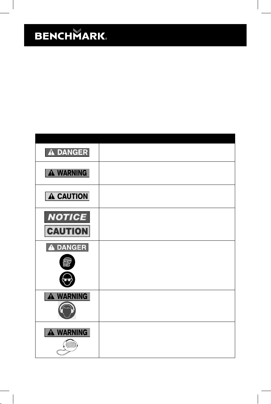
SYMBOL MEANING
Failure to obey a DANGER safety alert WILL result in serious personal
injury or death to you or to others. Always obey all messages following
this symbol to reduce the risk of serious personal injury or death.
Failure to obey a WARNING safety alert MAY result in serious personal
injury or death to you or to others. Always obey all messages following
this symbol to reduce the risk of potential serious personal injury or
death.
Failure to obey a CAUTION safety alert MAY result in personal injury
or property damage to you or to others. Always obey all messages
following this symbol to reduce the risk of personal injury or
property damage.
Failure to obey a NOTICE or a CAUTION (without a safety alert)
MAY result in property damage to you or to others. Always obey all
messages following this symbol to reduce the risk of property damage.
ALWAYS WEAR EYE PROTECTION THAT CONFORMS WITH CSA
Z94.3 or ANSI SAFETY STANDARD Z87.1
FLYING DEBRIS can cause permanent eye damage. Prescription
eyeglasses ARE NOT a replacement for proper eye protection. The
usage of a safety standard compliant face shield placed over proper
safety glasses or goggles can reduce the risk of facial injury.
Non-compliant eyewear can cause serious injury if broken during
the operation of a power tool.
Use hearing protection, particularly during extended periods of
operation of the tool, or if the operation is noisy.
WEAR A DUST MASK THAT IS DESIGNED TO BE USED WHEN
OPERATING A POWER TOOL IN A DUSTY ENVIRONMENT.
1150-002
INVERTER FLUX-CORE WELDER KIT
4
SYMBOL MEANING
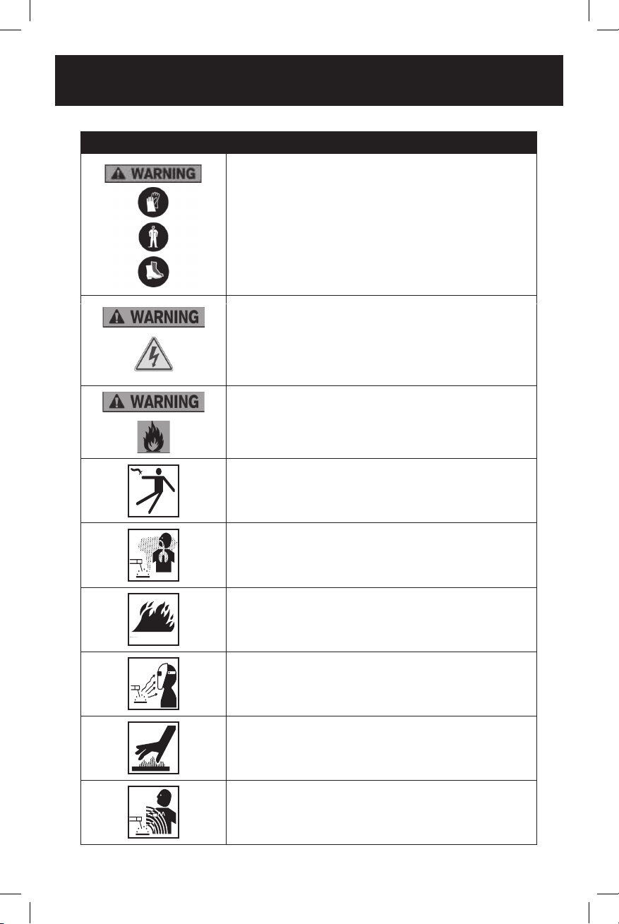
Always wear non-slip gloves that fit properly to protect your hands
and to help you grip the tool.
Always wear sturdy clothing with long sleeves and long pants.
Never operate the tool while wearing shorts, short sleeve shirt or
while shirtless.
Always wear non-slip safety boots to prevent foot injuries and slipping
that could cause loss of control of the tool.
To avoid electrical hazards, fire hazards or damage to the tool,
use proper circuit protection.
WARNING: Ventilation openings in batteries and chargers must
always be open to allow cooling air to circulate freely. Air vents that
are blocked, restricted or covered may result in the battery or charger
overheating. Overheating may lead to damage to the tool or cause a
fire, resulting in possible serious injury.
ELECTRIC SHOCK CAN KILL
FUMES AND GASES
FIRE HAZARDS
ARC RAYS
HOT MATERIALS
MAGNETIC FIELDS
This machine is wired at the factory for 120V AC operations.
Plug the power cord into a properly grounded, GFCI protected 120VAC
receptacle that matches the plug. The circuit must be equipped with
delayed action-type circuit breaker or fuses. To avoid shock or fire,
replace power cord immediately if it is worn, cut or damaged in any way.

5
GENERAL SAFETY INSTRUCTIONS
WARNING: OWNER’S MANUAL.
Read and understand this owner’s manual BEFORE using machine.
TRAINED OPERATORS ONLY. Untrained operators have a higher risk of being
hurt or killed. Only allow trained/supervised people to use this machine. When
machine is not being used, dis- connect power, remove switch keys, or lock-out
machine to prevent unauthorized use - especially around children. Make your
workshop kid proof!
DANGEROUS ENVIRONMENTS. Do not use machinery in areas that are wet,
cluttered, or have poor lighting. Operating machinery in these areas greatly
increases the risk of accidents and injury.
MENTAL ALERTNESS REQUIRED. Full mental alertness is required for safe
operation of machinery. Never operate under the influence of drugs or alcohol,
when tired, or when distracted.
ELECTRICAL EQUIPMENT INJURY RISKS. You can be shocked, burned, or
killed by touching live electrical components or improperly grounded machinery.
To reduce this risk, only allow qualified service personnel to do electrical
installation or repair work, and always disconnect power before accessing or
exposing electrical equipment.
DISCONNECT POWER FIRST. Always disconnect machine from power supply
before making adjustments, changing tooling, or servicing machine. This prevents
an injury risk from unintended startup or contact with live electrical components.
EYE PROTECTION. Always wear ANSI-approved safety glasses or a face shield
when operating or observing machinery to reduce the risk of eye injury or blindness
from flying particles. Everyday eyeglasses are NOT approved safety glasses.
WEARING PROPER APPAREL. Do not wear clothing, apparel or jewellery that
can become entangled in moving parts. Always tie back or cover long hair. Wear
non-slip footwear to reduce risk of slipping and losing control or accidentally
contacting cutting tool or moving parts.
HAZARDOUS DUST. Dust created by machinery operations may cause cancer,
birth defects, or long-term respiratory damage. Be aware of dust hazards
associated with each workpiece material. Always wear a NIOSH-approved
respirator to reduce your risk.
HEARING PROTECTION. Always wear hearing protection when operating or
observing loud machinery. Extended exposure to this noise without hearing
protection can cause permanent hearing loss.
REMOVE ADJUSTING TOOLS. Tools left on machinery can become dangerous
projectiles upon startup. Never leave chuck keys, wrenches, or any other tools on
machine. Always verify removal before starting!
USE CORRECT TOOL FOR THE JOB. Only use this tool for its intended purpose
- do not force it or an attachment to do a job for which it was not designed. Never
intended may result in malfunction or mechanical failure that can lead to personal
injury or death!

1150-002
INVERTER FLUX-CORE WELDER KIT
6
AWKWARD POSITIONS. Keep proper footing and balance at all times when
operating machine. Do not overreach! Avoid awkward hand positions that make
workpiece control dicult or increase the risk of accidental injury.
CHILDREN & BYSTANDERS. Keep children and bystanders at a safe distance
from the work area. Stop using machine if they become a distraction.
GUARDS & COVERS. Guards and covers reduce accidental contact with moving
parts or flying debris. Make sure they are properly installed, undamaged, and
working correctly before operating machine.
FORCING MACHINERY. Do not force machine. It will do the job safer and better at
the rate for which it was designed.
NEVER STAND ON MACHINE. Serious injury may occur if machine is tipped or if
the cutting tool is unintentionally contacted.
STABLE MACHINE. Unexpected movement during operation greatly increases risk
of injury or loss of control. Before starting, verify machine is stable and mobile base
(if used) is locked.
USE RECOMMENDED ACCESSORIES. Consult this owner’s manual or the
manufacturer for recommended accessories. Using improper accessories will
increase the risk of serious injury.
UNATTENDED OPERATION. To reduce the risk of accidental injury, turn machine
OFF and ensure all moving parts completely stop before walking away. Never leave
machine running while unattended.
MAINTAIN WITH CARE. Follow all maintenance instructions and lubrication
schedules to keep machine in good working condition. A machine that is improperly
maintained could malfunction, leading to serious personal injury or death.
DAMAGED PARTS. Regularly inspect machine for damaged, loose, or misaligned
parts - or any condition that could aect safe operation. Immediately repair/replace
before operating machine. For your own safety, DO NOT operate machine with
damaged parts!
MAINTAIN POWER CORDS. When disconnecting cord-connected machines
from power, grab and pull the plug—NOT the cord. Pulling the cord may damage
the wires inside. Do not handle cord/plug with wet hands. Avoid cord damage by
keeping it away from heated surfaces, high trac areas, harsh chemicals, and wet/
damp locations.
SERVICE
• Have your machinery serviced by a qualified repair person using only identical
replacement parts. This will ensure that the safety of the machinery is
maintained.

7
SPECIFIC SAFETY RULES FOR FLUX CORE WELDER
WARNING: In order to avoid mistakes that could cause serious injury, read the
following steps carefully and understand them thoroughly before using this welder.
WELDING FUMES. Breathing welding fumes can cause suocation or poisoning
without warning. Keep your head out of welding fumes. Use adequate ventilation at
the arc to safely remove the fumes from your breathing zone and the general area.
Use ANSI approved respirators for the type of welding operation. Protect others
from these fumes.
WELDING IN A CONFINED SPACE CAN BE HAZARDOUS. Always open all
covers, sustain forced ventilation, remove toxic and hazardous materials, and
provide a power disconnect to the welder inside the workspace. Always work with
someone who can give you help from outside the space. Welding can displace
oxygen. Always check for safe breathing atmosphere and provide air-supplied
respirators if necessary. Keep in mind that all normal welding hazards are intensified
in a confined space.
ELECTRIC SHOCK. DO NOT touch live electrical parts. Connect welder to power
source with approved earth ground. Make sure all electrical connections are tight,
clean, and dry. Connect workpiece to approved earth ground. The work lead is NOT
a ground connection and is to be used only to complete the working welding circuit.
PREVENT FIRES. Welding work zones must be kept clear of flammable liquids,
such as gasoline and solvents; combustible solids, such as paper and wood; and
flammable gases, such as acetylene and hydrogen. Provide approved fire barriers
and fire extinguishing equipment for the welding zone. Stay alert for sparks and
spatter thrown into cracks and crevices that can start a smoldering fire. Inspect the
work area again one hour after welding for any potential fire hazards.
WORKING AREA. Keep working area clear of any material not involved in the
welding operation. Keep all equipment, workpieces, and work surfaces clean, dry,
and free of entanglements. Keep lead cables organized and away from your body.
PROTECT BODY FROM ARC BURNS, SPARKS, AND SPATTER. Wear correct
and approved eye, ear, and body protection. Wear complete body protection, such
as clean and oil-free protective clothing, leather gloves, protective cap, heavy long-
sleeve shirt, cuess pants, and high leather boots. DO NOT wear jewellery or frayed
clothing. Use a welding helmet with the correct shade of filter for the operation.
Protect other people and property in your working zone from exposure to arc
radiation, sparks, and spatter.
HANDLING GAS CYLINDERS. Regardless of content, pressurized gas cylinders
can explode. Always secure a protector cap in place over the outlet valve assembly
when moving the cylinder. A broken o valve could release the pressurized contents
and cause the cylinder to be hurled about at dangerously high speeds, causing
serious property damage, personal injury, or death. Always use safe methods when
moving gas cylinders. Always secure a gas cylinder to a wall or approved cylinder
cart with a chain before using or storing.
PROTECT GAS CYLINDERS FROM HEAT OR DAMAGE. An excess of heat can
cause the pressurized gas to expand and explode the cylinder. Never weld on the
gas cylinder. Damaging the outside of the cylinder can cause the cylinder to crack

1150-002
INVERTER FLUX-CORE WELDER KIT
8
and explode. Exploding pressurized gas cylinders can cause serious property
damage, personal injury, or death.
ELECTRIC AND MAGNETIC FIELDS (EMF). Welding operations create EMF
around the welding equipment and workpieces. Workers who have pacemakers
must consult with their physician before using this equipment or being within 50
feet of welding operations.
EXPERIENCING DIFFICULTIES. If you are experiencing diculties performing the
intended operation, stop using the equipment.
Keep the environment you will be welding in free from flammable materials.
Always keep a fire extinguisher accessible to your welding environment.
Always have a qualified person install and operate this equipment.
Make sure the area is clean, dry and ventilated. Do not operate the welder in humid,
wet or poorly ventilated areas.
Always have your welder maintained by a qualified technician in accordance with
local, provincial and national codes.
Always be aware of your work environment. Be sure to keep other people, especially
children, away from you while welding.
Check all components to ensure they are clean and in good operating condition
before use.
Do not operate the welder if the output cable, wire, or any part of the system is wet.
Do not immerse them in water.
Do not allow any body part to come in contact with the wire if you are in contact with
the material being welded, ground or wire from another welder.
Do not weld if you are in an awkward position. Always have a secure stance while
welding to prevent accidents. Wear a safety harness if working above ground.
Do not drape cables over or around your body.
Wear a full-coverage helmet with shade (see ANSI Z87.1 safety standard)
and safety glasses while welding.
Wear proper gloves and protective clothing to prevent your skin from being exposed
to hot metals, UV and IR rays.
Do not overuse or overheat your welder.
Allow proper cooling time between duty cycles.
Always use this welder in the rated duty cycle to prevent excessive heat and failure.
Do not attempt to repair or maintain the welder while the power is on.
Do not touch the electrode and the ground or grounded work piece at
the same time.
Do not use a welder to thaw frozen pipes.
SAVE THIS USER MANUAL
WARNING:
MISUSE or failure to follow the safety rules stated in this instruction manual
may cause serious personal injury.

9
SAFETY SYMBOLS
The rating plate on your tool may show symbols. These represent important
information about the product or instructions on its use.
WARNING: Please read all of the safety and operating instructions
carefully before using this tool. Please pay particular attention to all
sections of this User Guide that carry warning symbols and notices. Some
of the following symbols may be used on this tool.
Observe caution and safety notes.
To reduce the risk of injury, user must read and understand User Guide
before using this tool.
Wear ear protection.
Wear protective helmet and eye protection.
maintenance.
Do not use in the rain or leave outdoors while it is raining.
Keep bystanders away.
Don’t touch the inlet and outlet when the vacuum cover is opened or the
tube is removed.
Double insulation.
Remove plug from the power source immediately if the power cord is
damaged or cut.
This symbol designates that this tool is listed with Canadian and U.S.
requirements by CSA Group conforms to CAN/CSA C22.2 No. 0; CAN/CSA C22.2
No. 0.4; CSA-C22.2 No. 60-M1990; UL551(8th Edition)
229683
Inverter FC 125
1150-002
INVERTER FLUX-CORE WELDER KIT
10
KNOW YOUR BENCHMARK FLUX CORE WELDER
Attention
Always be sure that the machinery is switched o and unplugged before adjusting
or checking function on the machinery.
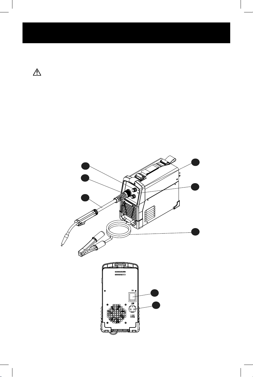
FUNCTIONS
1. POWER INDICATOR
2. OVERLOAD INDICATOR
3. WELDING CURRENT
4. VOLTAGE
5. WELDING CABLE AND FLUX-CORE GUN
6. GROUND CABLE AND CLAMP
7. ON/OFF SWITCH
8. POWER CORD
7
8
��
�
�
�
�
1
2
6
3
4
5

11
POWER INDICATOR
When the machine is turned on, the power indicator will be on.
Overload Indicator
When this indicator is on, it shows the machine is overloaded and the internal
temperature is too high. Weld output will turn o automatically but the fan will
still be working. When the internal temperature is decreased, the overload light
will turn o and the machine will be ready to weld.
Welding Voltage
Set output voltage and wire speed. Refer to the “set up” chart inside the
wire feed compartment.
Welding cable and Flux-Core Gun
The welding wire is driven through the welding cable and Flux-Core gun to
the work piece. It is fixed to the drive system.
Ground Cable and Clamp
The ground cable and clamp is attached to the work piece to complete
the flow of current needed to weld.
ON/OFF Switch
In the “o” position, no power is being supplied to the welder. In the “ON” position,
power is supplied to the main transformer and control circuit.
Power Cord
The power cord connects the welder to the 120-V power supply.
Plug into a 120-V/20-A receptacle to supply power to the welder

1150-002
INVERTER FLUX-CORE WELDER KIT
12
ASSEMBLY
INSTRUCTIONS FOR SHOULDER STRAP INSTALLATION
Step 1
Get the strap through
the buckle
Step 2
Step 4
Pull the strap tight enough until it is
locked in place by the buckle
Step 3
Pull the two ends through the buckle
Install the strap onto the machine
Leave 165 mm
on each end
Put the shoulder pad in
the middle of the strap
ASSEMBLY INSTRUCTIONS
1. Power requirement
AC single-phase 120 V (110-130 V), 60 Hz fused with a 20-A time-delayed fuse
or circuit breaker is required. DO NOT OPERATE THIS UNIT if the ACTUAL power
source voltage is less than 105 V AC or greater than 132 V AC.
BEFORE YOU START—DESCRIPTION
Connect your welder’s power cord to a properly grounded 120-V AC, 60-Hz, single-
phase, 20-A power source.
2. Extension cord
During normal use an extension cord is not necessary. It is strongly recommended
that an extension cord should not be used because of the voltage drop they
produce. This drop in voltage can aect the performance of the welder. If you need
to use an extension cord it must be a #12 gauge cord at the least. Do not use an
extension cord over 25' (7.6 m) in length.
13
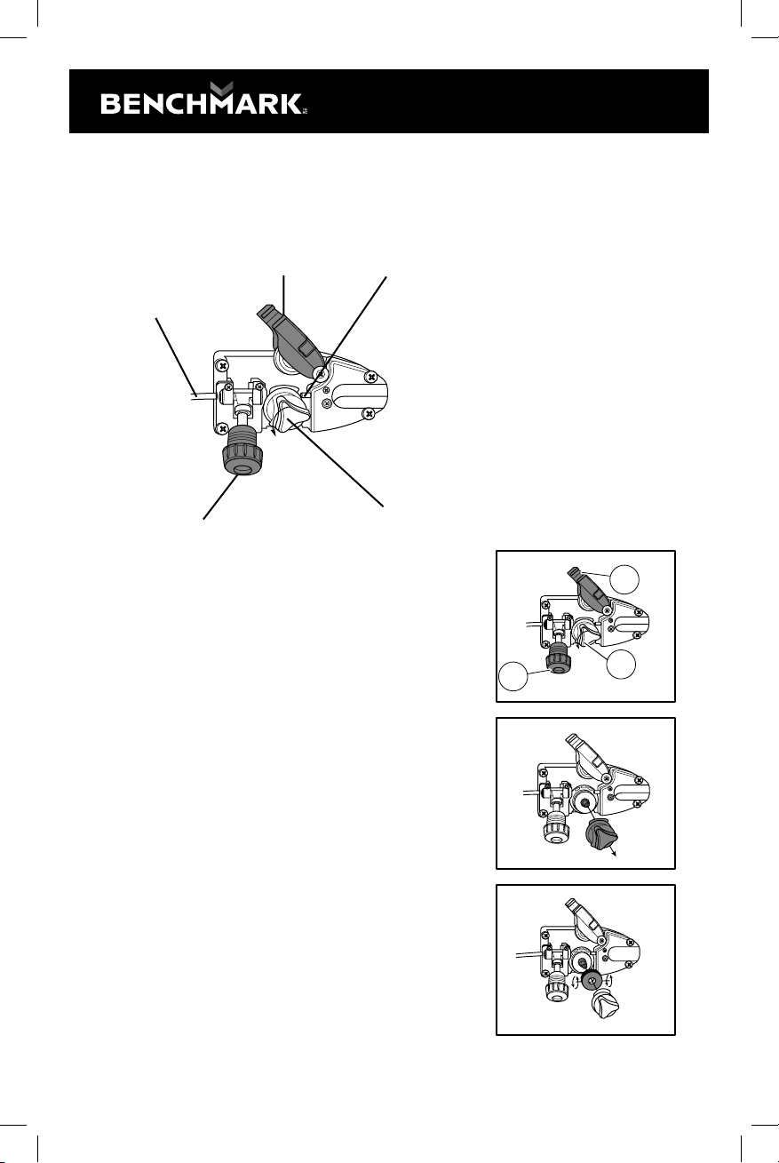
3. Install the wire roller
Before installing any welding wire into the unit, the properly-sized groove must be
positioned on the wire drive mechanism. Adjust the drive roller according to the
following steps, see following picture about the wire feeder structure:
3.1. Open the door to the welder drive compartment.
3.2. Remove the drive tension (see 1) by loosening
the tension adjusting knob and lifting the drive
tension adjustor away from the drive tension arm
(see 2).
Pull the drive tension arm away from the drive
roller (see 3). See following images for reference.
3.3. If a wire is already installed in the welder, roll it
back onto the wire spool by hand-turning the
spool counter-clockwise. Be careful not to allow
the wire to come out of the rear end of the inlet
guide tube without holding onto it or it will unspool
itself. Put the end of the wire into the hole on the
outside edge of the wire spool and bend it over to
hold the wire in place. Remove the spool of wire
from the drive compartment of the welder.
3.4. Rotate the drive roller cap counter-clockwise and
remove it from the drive roller.
3.5. Pull the drive roller o of the drive roller shaft.
Drive tension arm Gun liner
Drive roller
Drive tension arm
Inlet guide tube
6.
0
Fig 2
Fig 3
2
13
Fig 1
1150-002
INVERTER FLUX-CORE WELDER KIT
14
RECOMMENDED WIRE
3.6 Depending on the wire diameter, select the correct groove according to the
following table about the relationship between wire diameter and wire roller
groove size.
The drive roller has two wire-size grooves built
into it. When installing the drive roller, the number
stamped on the drive roller for the wire size you
are using should be facing you. Push the drive
roller onto the drive roller shaft.
3.7. Reinstall the drive roller cap and lock in place by turning it clockwise.
3.8. Close the door to the welder drive compartment.
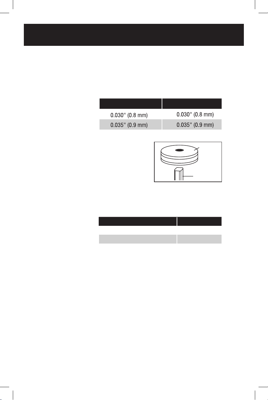
4. Install the wire
4.1 Select the wire.
4" (10 cm) wire spools of 0.030" (0.8 mm) or 0.035" (0.9 mm).
Self-shielding flux-core wire can be used on this welder.
Steel from 18 gauge up to 3/16” thick can be welded with this wire.
NOTE:
- Metal thinner than 18 gauge cannot be welded with this machine. Attempting
to do so will cause burn-through in the metal you are intending to weld.
- Remove any wire that is rusty; if the whole spool is rusty, discard it.
This welder uses both 4" (10 cm) spools of 0.030 or 0.035"
(0.8 or 0.9 mm) thick wire.
4.2 Install the wire.
4.2.1 Remove the nozzle and contact tip from the end of the torch assembly.
4.2. 2 Make sure the proper groove on the drive roller is in place for
the wire installed.
Wire Diameter Roller Groove
Motor shaft
Drive
roller
0.035
MIG wire No
Flux-core wire 0.030" (0.8 mm)
Flux-core wire 0.035" (0.9 mm) Yes
Wire Type Available or not
Yes
FLUX CORED WIRE SELECTION---- E71T-GS

15
If not, change the drive roller as described above.
4.2.3 Unwrap the spool of wire and then find the leading end of the wire. The wire
goes through a hole in the outer edge of the spool and is bent over the spool edge to
prevent the wire from unspooling BUT DO NOT UNHOOK IT at this point.
4.2.4 Place the spool on the spool holder in such a manner that the welding wire
comes o the bottom of the spool into the drive mechanism. See following diagram.
WARNING!
Electric shock can kill! Always turn the POWER switch OFF and unplug the power
cord from the AC power source before installing wire.
• Metal thinner than 18 gauge cannot be welded with this machine. Attempting to
do so will cause burn through in the metal you are intending to weld.
•
If the wire is rusty, remove any wire with rust. If the whole spool is rusty, discard it.
• Before installing, make sure that you have removed any old wire from the torch
assembly. This will help to prevent the possibility of the wire jamming inside the
torch liner.
• Be very careful when removing the welding nozzle. The contact tip on this welder
is live whenever the torch trigger is pulled. Make sure the POWER is turned OFF.
4.2.5 The welder can use 4" (10 cm) spool, please see the following chart. The
adjustment knob is designed to adjust the pressure tension of the wire spool.
4.2.6. Once adjustment knob is installed, set the spool tension.
a) With one hand, turn the wire spool and continue turning it while adjusting
the tension on the spool.
b) With your free hand, tighten the drive tension adjustment knob.
c) Stop tightening when drag is felt on the wire spool that you are turning,
then stop hand-turning the wire spool.
Wire installation
Right way Wrong way
4" (10 cm)
spool

4.2.7. After checking to make sure that your welder is disconnected from the AC
power source, free the leading end of the wire from the spool, but do not let go of it
until told to do so, or the wire will unspool itself.
4.2.8. Using a wire cutter, cut the bent end o the leading end of the wire so that
only a straight leading end remains.
4.2.9. Loosen the tension adjusting knob holding the drive tension arm in place
and lift the tension arm up o the drive roller.
4.2.10. Insert the leading end of the wire into the inlet guide tube.
Then push it across the drive roller and into the torch assembly about 6" (15 cm).
4.2.11. Line the wire up to place in the groove of drive roller, then allow the drive
tension arm to drop onto the drive roller.
4.2.12. Flip the quick-release drive tension back up into position on the
drive tension arm.
4.2.13. Tighten (turn clockwise) the drive tension adjusting knob until the
tension roller is applying enough force on the wire to prevent it from slipping
out of the drive assembly.
4.2.14. Let go of the wire.
CAUTION
If TOO MUCH tension is applied to the wire spool, the wire will slip on the drive roller
or will not be able to feed at all. If TOO LITTLE tension is applied, the spool of wire
will want to unspool itself. Readjust the drive brake tension as necessary to correct
for either problem.
4.2.15. Connect the welder power cord to the AC power source. Turn the welder
ON. Set the VOLTAGE switch to the voltage (heat) setting recommended for the
gauge metal that is to be welded. Refer to the label mounted on the cover, inside
the drive compartment.
4.2.16. Set the WIRE SPEED control to the middle of the wire speed range.
4.2.17. Straighten the torch cable and pull the trigger on the welding torch to feed
the wire through the torch assembly. When at least 1" (2.5 cm) of the wire sticks
out past the end of the torch, release the trigger.
4.2.18. Turn the power switch to the OFF position.
4..2.19. Select a contact tip stamped with the same diameter as the wire being used.
NOTE: Due to inherent variances in flux-cored welding wire, it may be necessary
to use a contact tip one size larger than your flux core wire if wire jams occur.
4.2.20. Slide the contact tip over the wire (protruding from the end of the torch).
Thread the contact tip into the end of the torch and hand-tighten securely.
4.2.21. Install the nozzle on the torch assembly. For best results, coat the insid
of the nozzle with antistick spray or gel.
4.2.22. Cut o the excess wire that extends past the end of the nozzle.
4.2.23. Turn the welder ON.
5. Setting the wire tension
5.1. Press the trigger on the torch.
1150-002
INVERTER FLUX-CORE WELDER KIT
16

17
5.2. Turn the drive tension adjustment knob clockwise, increasing the drive tension
until the wire seems to feed smoothly without slipping.
WARNING:
Arc flash can injure eyes! To reduce the risk of arc flash, make sure that the wire
coming out of the end of the torch does not come into contact with work piece,
ground clamp or any grounded material during the drive tension setting process, or
arcing will occur.
OPERATION
1. Main control component
Power switch - The power switch supplies electrical current to the welder. Whenever
the power switch is in the ON position, the welding circuit is activated. ALWAYS turn
the power switch to the OFF position and unplug the welder before performing any
maintenance.
Voltage selector - The voltage selector controls the welding heat. This unit has two-
step voltage control. Refer to the label inside the welder side door for recommended
voltage selector settings for your welding job.
Wire speed control - The wire speed control adjusts the speed at which the wire
is fed out of the welding torch. The wire speed needs to be closely matched
(tuned in) to the rate at which it is being melted o. Some things that aect wire
speed selection are the type and diameter of the wire being used, the heat setting
selected, and the welding position to be used.
Note: The wire will feed faster without an arc. When an arc is being drawn, the wire
speed will slow down.
2. Hold the torch
The best way to hold the welding torch is the way that feels most comfortable to you.
While practicing using your new welder, experiment holding the torch in dierent
positions until you find the one that seems to work best for you.
3. Position the torch to the work piece
There are two angles of the torch nozzle in relation to the work piece that must be
considered when welding.
3.1. Angle A can be varied, but in most cases the optimum angle will be 60
degrees, the point at which the torch handle is parallel to the work piece. If angle
A is increased, penetration will increase. If angle A is decreased, penetration will
decrease as well.

1150-002
INVERTER FLUX-CORE WELDER KIT
18
3.2. Angle B can be varied for two reasons: to improve the ability to see the arc in
relation to the weld puddle and to direct the force of the arc.
4. Distance from the work piece
If the nozzle is held o the work piece, the distance between the nozzle and the
work piece should be kept constant and should not exceed 1/4" (6 mm) or the arc
may begin sputtering, signaling a loss in welding performance.
5. Tuning in the wire speed
This is one of the most important parts of MIG welder operation and must be done
before starting each welding job or whenever any of the following variables are
changed: heat setting, wire diameter, or wire type.
5.1. Connect the ground clamp to a scrap piece of the same type of material which
you will be welding. It should be equal to or greater than the thickness of the actual
work piece, and free of oil, paint, rust, etc.
5.2. Select a heat setting.
5.3. Hold the torch in one hand, allowing the nozzle to rest on the edge of the
workpiece farthest away from you, and at an angle similar to that which will be used
when welding.
5.4. With your free hand, turn the wire speed dial to maximum and continue to hold
onto the knob.
5.5. Lower your welding helmet and pull the trigger on the torch to start an arc, then
begin to drag the torch toward you while simultaneously turning the wire speed dial
counter-clockwise.
5.6. LISTEN! As you decrease the wire speed, the sound that the arc makes will
change from a sputtering to a high-pitched buzzing sound and then will begin
sputtering again if you decrease the wire speed too much. The point on the wire
speed adjustment where the high-pitched buzzing sound is achieved is the correct
setting. You can use the wire speed control to slightly increase or decrease the heat
and penetration for a given heat setting by selecting higher or lower wire speed
settings. Repeat this tune-in procedure if you select a new heat setting, a dierent
diameter wire, or a dierent type of welding wire.
6. Welding Techniques
6.1 Moving the torch
Torch travel refers to the movement of the torch along the weld joint and is broken
into two elements: direction and speed. A solid weld bead requires that the welding
torch be moved steadily and at the right speed along the weld joint. Moving the
torch too fast, too slow, or erratically will prevent proper fusion or create a lumpy,
uneven bead.

19
Travel direction is the direction the torch is moved along the weld joint in relation to
the weld puddle. The torch is either PUSHED into the weld puddle or PULLED away
from the weld puddle.
For most welding jobs, you will pull the torch along the weld joint to take advantage
of the greater weld puddle visibility.
Travel speed is the rate at which the torch is being pushed or pulled along the weld
joint. For a fixed heat setting, the faster the travel speed, the lower the penetration
and the lower and narrower the finished weld bead. Likewise, the slower the travel
speed, the deeper the penetration and the higher and wider the finished weld bead.
6.2. Types of welding bead
As you become more familiar with your new
welder and better at laying some simple weld
beads, you can begin to try some dierent weld
bead types.
The stringer bead is formed by travelling with
the torch in a straight line while keeping the
wire and nozzle centered over the weld joint.
See following figure.
The weave bead is used when you want to
deposit metal over a wider space than would
be possible with a stringer bead. It is made by
weaving from side to side while moving with the
torch. It is best to pause momentarily at each
side before weaving back the other way.
6.3 Welding position
FLAT POSITION This is easiest of the welding
positions and is most commonly used. It is
best if you can weld in the flat position if at all
possible as good results are easier to achieve.
Push Pull
Weld
puddle
Table of contents
Popular Inverter manuals by other brands


Agilent Technologies
Agilent Technologies E8247C PSG CW user guide

Dometic
Dometic TEC60 operating manual

Duracell
Duracell Digital inverter 400 owner's guide

Terex
Terex T25 Service manual

Omnik New Energy
Omnik New Energy Omniksol-1k-TL2 user manual

Morningstar
Morningstar SureSine 150 Installation and operation manual


