manuals.online logo
Brands
  1. Home
  2. •
  3. Brands
  4. •
  5. MYERS
  6. •
  7. Inverter
  8. •
  9. MYERS LVU-2 User manual

MYERS LVU-2 User manual

INSTRUCTION MANUAL
SAVE THIS INSTRUCTIONS
LVU-2/5
WWW.MYERSEPS.COM
UNIVERSAL MICRO INVERTER
PURE SINUSOIDAL AC OUTPUT
OUTPUT VOLTAGE AUTO SETTING EQUAL TO INPUT VOLTAGE
AUTO DIMMING (1-10V) OF CONNECTED LOAD
IMPORTANT SAFEGUARDS
WHEN USING ELECTRICAL EQUIPMENT, BASIC SAFETY PRECAUTIONS SHOULD ALWAYS BE FOLLOWED, INCLUDING THE FOLLOWING
READ AND FOLLOW ALL SAFETY INSTRUCTIONS
1. To prevent electric shock, switch off the mains power until installation is complete and
AC input power is supplied to this product.
2. This product requires an unswitched AC power supply of 120-277V, 50/60Hz.
3. Make sure all connections are in accordance with the National or Canadian Electrical
code and any local regulations.
4. To reduce the risk of electrical shock, disconnect both normal power, emergency power
supplies and unit connector of this product before servicing.
5. For emergency operation of LED, incandescent, fluorescent fixtures and screw-base
lamps.
6. Use this product in 0°C minimum, 50°C maximum ambient temperatures (Ta). To ensure
the emergency operating time over 90 minutes, the output emergency power of LVU-2/5
should be maximum of 25W for the LVU-2 and 50W for the LVU-5.
7. Use with grounded, UL Listed, damp location rated fixtures. Do not use outdoors. Do
not mount it near gas, heaters, air outlets or other hazardous locations.
8. Do not attempt to service the batteries. A sealed, non-maintenance battery is used that
is not field replaceable. Contact the manufacturer for information or service.
9. The use of accessory equipment not recommended by the manufacturer may cause an
unsafe condition and void warranty.
10. Do not use this product for other than intended use.
11. Installation and service should be performed by qualified service personnel.
12. This product should be mounted in locations and at heights where it will not readily be
subjected to tampering by unauthorized personnel.
E95719
18G9
44 South Commerce Way, Bethlehem, PA 18017 Technical Support: 610-868-5400
THIS PRODUCT CONTAINS A RECHARGEABLE NICKEL-CADMIUM BATTERY.
THE BATTERY MUST BE RECYCLED OR DISPOSED OF PROPERLY.
Ni-cd
INSTALLATION
2/4
OUTSIDE THE LUMINAIRE
LVU-2/5
1. SPECIFICATION OF LVU-2/5
2. INSTALLING THE LVU-2/5
The LVU-2/5 can be mounted inside or outside (nearby or on top of) the luminaire.
3. INSTALLING THE LED TEST SWITCH (LTS)
Select a convenient location for the LTS so that it can be seen after installation.
Drill a 1/2"(12 mm) hole for mounting the LTS. Connect the wires from LTS to the
LVU-2/5 model according to the wiring diagram on page 3.
INSIDE THE LUMINAIRE
LVU-2/5
CAUTION: MAKE CERTAIN THE AC POWER IS OFF AND THE LVU-2/5 UNIT CONNECTOR IS
DISCONNECTED UNTIL THE INSTALLATION IS COMPLETE.
WWW.MYERSEPS.COM
LED test switch
LED test switch
One 7/8" (22mm) hole
with conduit connector for LVU-2/5
LVU-2 LVU-5
Output
Output power
Voltage
Input
208V/60Hz
120V/60Hz
25W 50W
208V/60Hz
120V/60Hz
277V/60Hz 277V/60Hz
44 South Commerce Way, Bethlehem, PA 18017 Technical Support: 610-868-5400
3/4
WIRING
CAUTION: DO NOT MATE UNIT CONNECTOR UNTIL INSTALLATION IS COMPLETE AND
AC POWER IS SUPPLIED.
WWW.MYERSEPS.COM
ANY QUANTITY
LVU-2/5
YELLOW
BLACK
YELLOW/GREEN
WHITE
NEUTRAL
GROUND
SWITCH
HOT
LED Test Switch
120-277 VAC
LED
FLUORESCENT
INCANDESCENT
LUMINAIRE
RED (+)
RED/WHITE (-)
RED (+)
RED/WHITE (-)
DIM IN VIOLET (+)
DIM IN GRAY (-)
①
①
④
⑤
⑥
⑦
WHITE/ORANGE (OUT NEUTRAL) ③
ORANGE (OUT HOT) 120-277 VAC
③
⑥
BROWN UNIT CONNECTOR
BROWN
LED
FLUORESCENT
INCANDESCENT
LUMINAIRE
LED
FLUORESCENT
INCANDESCENT
LUMINAIRE
FOR EMERGENCY
LED
FLUORESCENT
INCANDESCENT
LUMINAIRE
FOR EMERGENCY
0-10V
DIMMER
DIM OUT VIOLET/WHITE (+)
DIM OUT GRAY/WHITE (-)
②
②
* The max. linkable luminaire quantity for
emergency will be different due to different
electrical appliances, which needs to be
verified by end users.
WIRING DIAGRAM FOR NON-DIMMABLE EMERGENCY LIGHTING SYSTEM
TOTAL POWER LVU-2=25W
ANY QUANTITY
LVU-5=50W
LVU-2/5
YELLOW
BLACK
YELLOW/GREEN
WHITE
NEUTRAL
GROUND
SWITCH
HOT 120-277 VAC
LED
FLUORESCENT
INCANDESCENT
LUMINAIRE
RED/WHITE (-) RED/WHITE (-)
DIM IN VIOLET (+)
DIM IN GRAY (-)
①
LED Test Switch
RED (+) RED (+)
①
④
⑤
⑥
⑦
WHITE/ORANGE (OUT NEUTRAL) ③
ORANGE (OUT HOT) 120-277 VAC
③
⑥
BROWN UNIT CONNECTOR
BROWN
LED
FLUORESCENT
INCANDESCENT
LUMINAIRE
LED
FLUORESCENT
INCANDESCENT
LUMINAIRE
FOR EMERGENCY
LED
FLUORESCENT
INCANDESCENT
LUMINAIRE
FOR EMERGENCY
DIM OUT VIOLET/WHITE (+)
DIM OUT GRAY/WHITE (-)
②
②
1. The LVU-2/5 requires an unswitched AC power supply of 120-277 volt, 50/60Hz.
2. For all loads connect hot wire to black.
3.For Normally On Loads-Connect Hot wire to Yellow. For Normally Off Loads-Yellow wire is not Connected.
Switched Loads-Connect switch to Yellow wire.
4. Refer to the wiring diagrams below. Make connections in the following order 1 2 3 4 5 6 7
5. Consult the factory for other wiring diagram.
WIRING DIAGRAM FOR 1-10V DIMMABLE EMERGENCY LIGHTING SYSTEM
Cap unused leads
Cap unused leads
TOTAL NORMAL POWER 125W DIMMED TO 25W (LVU-2)
250W DIMMED TO 50W (LVU-5)
44 South Commerce Way, Bethlehem, PA 18017 Technical Support: 610-868-5400
REMOTE TEST
SHOWN WITH OPTIONAL
REMOTE TEST SWITCH
REMOTE TEST
SHOWN WITH OPTIONAL
REMOTE TEST SWITCH
4/4
OPERATION / TESTING / MAINTENANCE
WWW.MYERSEPS.COM
OPERATION
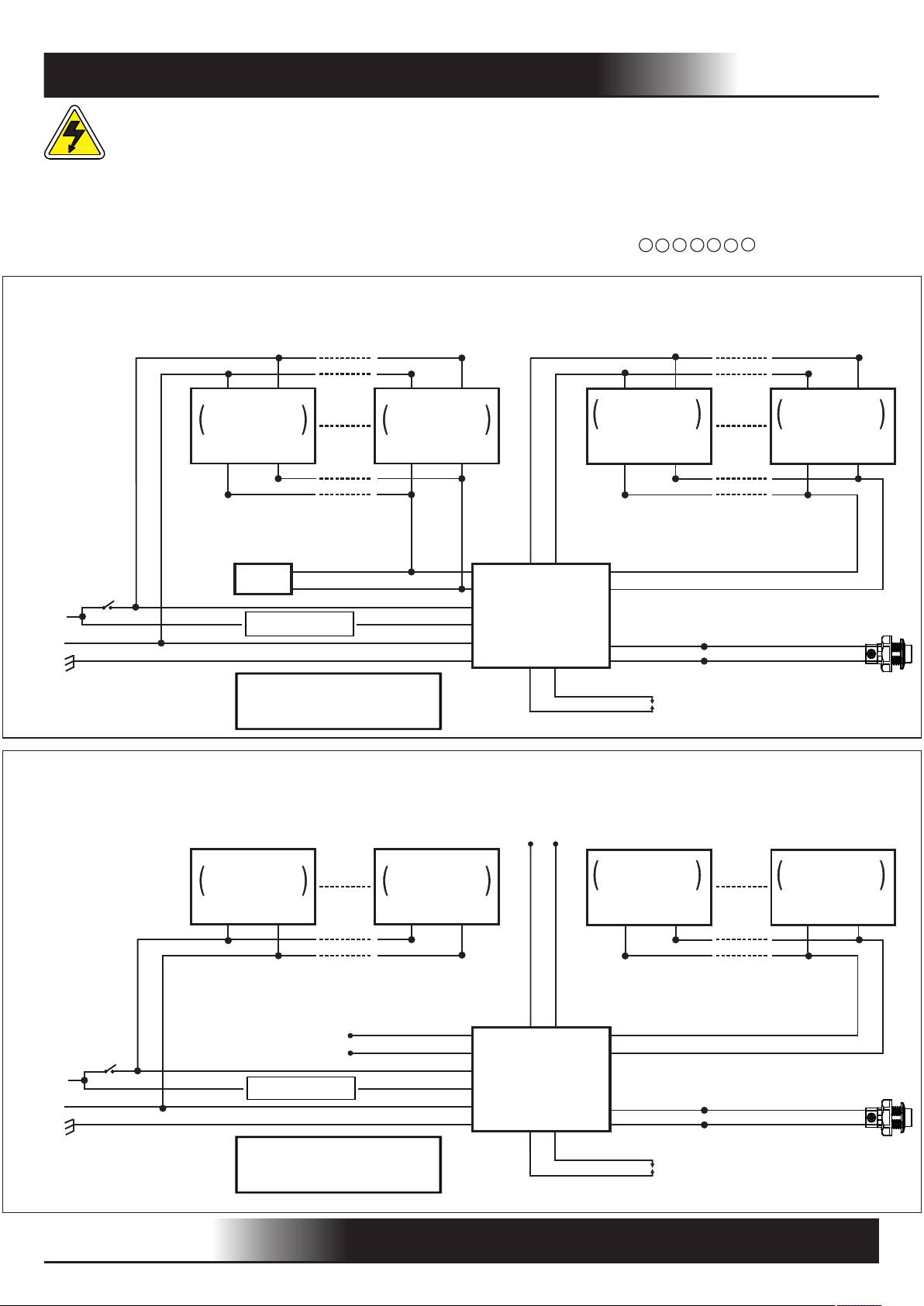
When AC power is applied, the LED test switch (LTS) is illuminated, indicating that the batteries are being charged.
When AC power fails, the LVU-2/5 automatically switches to emergency (battery) power, which can be maintained
for >90 minutes, operating the loads specified emergency power level. The LTS is switched off. When AC power is
restored, the LVU-2/5 switches the system back to normal mode and resumes battery charging. The charging time
for the full discharged battery is 24 Hours.
TESTING AND MAINTENANCE
Periodic tests are recommended to ensure the system is functioning normally:
1. Visually inspect the LTS monthly. It should be illuminated when AC power is applied.
2. Conduct a 30 second discharge test by switching off the mains power every month.
3. Conduct a 90 minute discharge test once per year. The loads should be illuminated at least 90 minutes.
AUTO TEST
The LVU-2/5 series has integrated Auto Test functions as follows:
1. Instant Auto Test
When the system is connected and powered on, the LVU-2/5 model will Auto Test to verify proper connection of
LED load and connection/charging of battery pack. In case of LED load or Battery pack problem, the LTS will flash.
When the abnormal condition is corrected, the LTS will stop flashing.
2. Preprogrammed Auto Test
1) The initial monthly Auto Test begins 24 hours to 7 days after initial power up; monthly Auto Tests repeat once
every 30 days.
2) Annual Auto Tests repeat every 52 weeks after initial power up.
- Monthly Auto Test
Monthly Auto Test is executed every 30 days, testing:
(a)Transfer from normal to emergency mode, and the reverse;
(b)Battery charging in normal mode and discharging in emergency mode;
Test time is about 30 seconds.
- Annual Auto Test
Annual Auto Test is executed every 52 weeks after 24 hours full charging, testing:
(a)Transfer from normal to emergency mode, and the reverse;
(b)Emergency operation meets 90 minutes minimum; And battery voltage after 90 minutes emergency operation
is equal or higher than 87.5% of initial voltage.
3) During Auto Test, in case of power failure and cannot be on till the auto test completes, the Auto Test will be
executed again 24 hours after the power has been resumed.
4) If the emergency mode causes the battery discharged completely under the power-off condition, the
Preprogrammed Auto Test will be reset after power has been resumed.
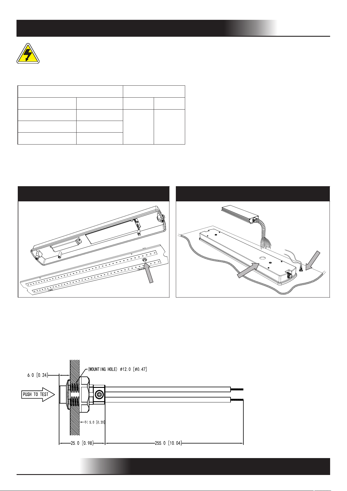
MANUAL TEST
- Press LTS one time to simulate emergency mode.
- Press LTS 2 times within 5 seconds to initiate monthly test. Upon completion of this test, the Monthly auto-test
counter is set to repeat after 30 days.
- Press LTS 3 times within 5 seconds to initiate annual test. Upon completion of this test, the Annual auto-test
counter is set to repeat after 52 weeks.
- During the manual test, press and hold the LTS for longer than 3 seconds or press LTS 3 times to terminate the
test. (The next-occurring preprogrammed Auto Tests – Monthly and Annual -- will remain scheduled).
LED test switch (LTS) INDICATION
- LTS slow flash: In charging
- LTS on: Normal
- LTS off: Power failure
- LTS gradual change: In testing mode
- LTS quick flickering: Abnormal condition - Corrective required
44 South Commerce Way, Bethlehem, PA 18017 Technical Support: 610-868-5400

This manual suits for next models

1

Other MYERS Inverter manuals

MYERS LVM-125 User manual

MYERS

MYERS LVM-125 User manual

MYERS EM Series User manual

MYERS

MYERS EM Series User manual

MYERS Illuminator System CM Series User manual

MYERS

MYERS Illuminator System CM Series User manual

MYERS Illuminator Supernova Series User manual

MYERS

MYERS Illuminator Supernova Series User manual

MYERS EM Series Operation manual

MYERS

MYERS EM Series Operation manual

MYERS LV Series User manual

MYERS

MYERS LV Series User manual

MYERS LVU-2 User manual

MYERS

MYERS LVU-2 User manual

Popular Inverter manuals by other brands

Hitachi NES1-OP Basic Manual

Hitachi

Hitachi NES1-OP Basic Manual

Steca coolcept StecaGrid 1500 Installation and operating instructions

Steca

Steca coolcept StecaGrid 1500 Installation and operating instructions

Sterling Power Pro Power SB Series quick start guide

Sterling Power

Sterling Power Pro Power SB Series quick start guide

EINHELL GC-PW-4030 Service manual

EINHELL

EINHELL GC-PW-4030 Service manual

enphase IQ 7 Installation and operation manual

enphase

enphase IQ 7 Installation and operation manual

GoWISE Power Tech-On PS1001 user manual

GoWISE

GoWISE Power Tech-On PS1001 user manual

WFCO WF-5300 Series product manual

WFCO

WFCO WF-5300 Series product manual

Huawei SUN2000L-5KTL quick guide

Huawei

Huawei SUN2000L-5KTL quick guide

Grape Solar GS-PWM-20A Quick connect guide

Grape Solar

Grape Solar GS-PWM-20A Quick connect guide

Huawei SUN2000-111KTL-NHM0 quick guide

Huawei

Huawei SUN2000-111KTL-NHM0 quick guide

SolaX Power X3-Matebox Quick installation guide

SolaX Power

SolaX Power X3-Matebox Quick installation guide

Champion 201003 quick start guide

Champion

Champion 201003 quick start guide

Meanwell PB-300 instruction manual

Meanwell

Meanwell PB-300 instruction manual

SUNGOLD POWER LFPV Series user manual

SUNGOLD POWER

SUNGOLD POWER LFPV Series user manual

OutBack Power GS7048E Operator's manual

OutBack Power

OutBack Power GS7048E Operator's manual

Go Power GP-1000 owner's manual

Go Power

Go Power GP-1000 owner's manual

Delta RPI H3 110 Quick installation guide

Delta

Delta RPI H3 110 Quick installation guide

East EAHI-6000-SL manual

East

East EAHI-6000-SL manual

manuals.online logo
manuals.online logoBrands
  • About & Mission
  • Contact us
  • Privacy Policy
  • Terms and Conditions

Copyright 2025 Manuals.Online. All Rights Reserved.