Bend-Pak 1000-BL Operation manual
1 Bender Operation Manual Revision 90196
BendPak®
INCORPORATED
Bend-Pak®
INCORPORATED
FORWARD THIS MANUAL TO ALL
OPERATORS. FAILURE TO OPERATE
THIS EQUIPMENT AS DIRECTED HEREIN
MAY CAUSE INJURY
OPERATION AND SERVICE MANUAL
“America’s Most Popular
Tubing Bender”
Models:
1000-BL 1302-BL (“Blue Bullet”)
1000-BAS 1302-BAS
1000-BA 1302-BA
1502-BL
1502-BAS
1502-BA
Model 1502-BA
shown with typical
tooling package.
SHIPPING DAMAGE CLAIMS
When this equipment is shipped, title passes to the pur-
chaser upon receipt from the carrier. Consequently, claims
for material damaged in shipment must be made by the
purchaser against the transportation company at the time
shipment is received.
BE SAFE
Bend-Pak, Inc. benders are designed and built with safety
in mind. However, your overall safety can be increased by
proper training and thoughtful operation on the part of the
operator. DO NOT operate or repair this equipment without
reading this manual and the important safety instructions
shown inside.
1645 Lemonwood Drive
Santa Paula, CA 93060 U.S.A.
Tel: 805-529-3675
Fax: 805-529-2909

TABLE OF CONTENTS
Identification Data / Warranty.....................................................................................................................................3
Specifications .............................................................................................................................................................4
Important Safety Instructions......................................................................................................................................5
Definition Of Terms / Model Identification ..................................................................................................................6
Installing The Electrical Plug ......................................................................................................................................7
Turning Your New Bender On ....................................................................................................................................8
Introduction Of Tooling Identification ..........................................................................................................................8
Segment Identification Chart..................................................................................................................................... 11
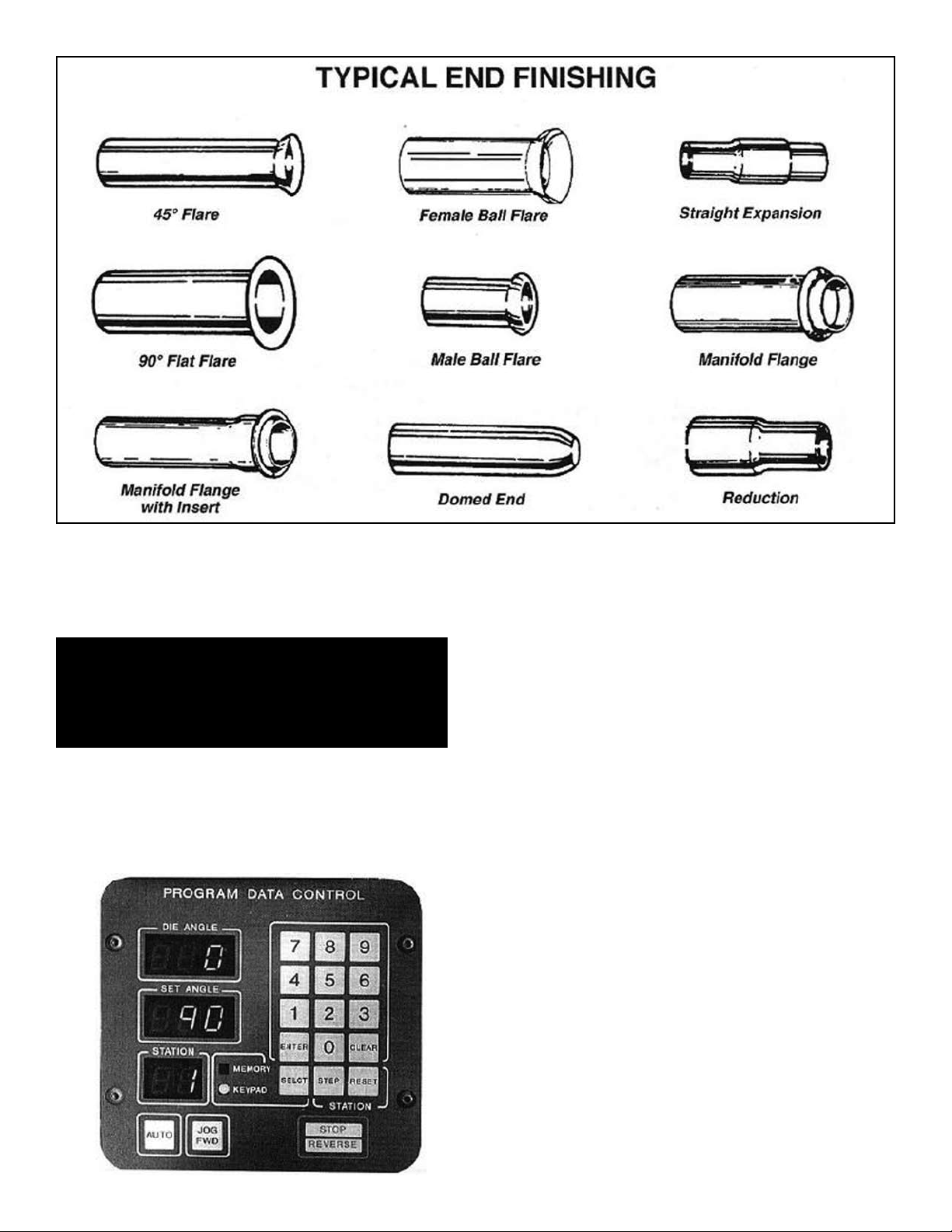
Typical End Finishing Illustrations .............................................................................................................................12
Description Of Digital Controls (BA Models) .............................................................................................................12
Operating The Digital Control Board (BA Models) ....................................................................................................13
Description Of Three-Button Control ((BAS Models) ................................................................................................14
Operating The Manual Knee Control (BL / Bullet Models)........................................................................................15
Introduction Of Bending Operations..........................................................................................................................15
Using The Program Cards ........................................................................................................................................15
Pattern Bending.........................................................................................................................................................19
Blank Program Card..................................................................................................................................................20
Three Inch Tube Bending Procedure ........................................................................................................................21
Stainless Tube Bending Procedure...........................................................................................................................22
Using The Standard Segment Expanders.................................................................................................................23
Using The Ball-Joint Segment Expanders ................................................................................................................24
Using The Flare Segment Expanders.......................................................................................................................24
Using The Manifold Flange Segment Expanders .....................................................................................................25
Introduction Of The Swager Assembly......................................................................................................................25
Using The STED Expander Dies...............................................................................................................................25
Making Male Ball Expansions ...................................................................................................................................26
Making Female Ball Expansions ...............................................................................................................................27
Making 45 Degree Flares..........................................................................................................................................27
Making A Manifold Flange Using The HPF-300 Tool ................................................................................................28
Making A Manifold Flange Using The CFT Tool........................................................................................................30
Using the Reducing Tool ...........................................................................................................................................30
Using The Doming Die To Finish Tailpipe Ends ........................................................................................................31
Making Header Collectors Using the HCT-2I4/2I2 Tool ............................................................................................ 3I
Maintenance Introduction ..........................................................................................................................................32
Hydraulic Oil Service.................................................................................................................................................32
Recommended Weekly / Monthly Maintenance........................................................................................................32
Pressure Settings ......................................................................................................................................................33
Chain Adjusting Procedure........................................................................................................................................34
Aligning The Guide Plate ..........................................................................................................................................35
Barrel Bushing Maintenance .....................................................................................................................................36
Aligning The Swager Box Cylinder............................................................................................................................37
Pusher Block Maintenance........................................................................................................................................38
Calibrating The Depth-Of-Bend Plate Manual Models..............................................................................................39
Calibrating The Depth-Of-Bend Switch (BAS Models).............................................................................................. 39
Calibrating The Digital Readout Display (BA Models)...............................................................................................40
Using The Jumper Board BA Models........................................................................................................................41
Operating The Machine Manually Using The Solenoid Valve...................................................................................42
Solenoid Valve Maintenance .....................................................................................................................................43
Checking The Micro Switches (Automatic Models)..................................................................................................43
Motor Lead Connections ...........................................................................................................................................43
Checking Motor Rotation...........................................................................................................................................44
Manual Electric Starter..............................................................................................................................................44
Trouble Shooting Procedures................................................................................................................................. 45-47
Bending Problems .....................................................................................................................................................48
Electrical Wiring Diagrams (Models BA & BAS)..................................................................................................... 49,50
Service Parts .............................................................................................................................................................51
Deluxe 302 Die Package...........................................................................................................................................52
Economy 202 Die Package.......................................................................................................................................53
BB-1 Die Package For Blue Bullet ............................................................................................................................54
BB-2 Die Package For Blue Bullet ............................................................................................................................55
2 Bender Operation Manual

3 Bender Operation Manual
YOUR NEW BENDER
This instruction manual has been prepared especially for you.
Your new bender is the product of over 25 years of continuous research, testing and
development and is the most technically advanced bender on the market today.
READ THIS ENTIRE MANUAL BEFORE OPERATION BEGINS.
The manner in which you care for and maintain your bender will have a direct effect on
it's overall performance and longevity.
RECORD HERE THE FOLLOWING INFORMATION WHICH IS LOCATED AT THE
FRONT END OF YOUR MACHINE.
Serial No. _________________
Model No. _________________
Manufacturing date __________
Bender Operation Manual 3
WARRANTY
Your new bender is warranted for two years on equipment structure; one year on
all operating components and tooling to the original purchaser, to be free of defects
in material and workmanship. The manufacturer shall repair or replace at their
option for this period those parts returned to the factory freight prepaid which prove
upon inspection to be defective. The manufacturer will pay labor costs for the first
l2 months only on parts returned as previously described.
This warranty does not extend to defects caused by ordinary wear, abuse,
misuse, shipping damage, or lack of required maintenance.
This warranty is exclusive and in lieu of all other warranties expressed or implied.
In no event shall the manufacturer be liable for special, consequential or incidental
damages for the breach or delay in performance of the warranty. The manufacturer
reserves the right to make design changes or add improvements to its product line
without incurring any obligation to make such changes on product sold previously.
Warranty adjustments within the above stated policies are based on the model
and serial number of the equipment. This data must be furnished with all
warranty claims.
WARRANTY IS NOT VALID UNLESS
WARRANTY CARD IS RETURNED

4 Bender Operation Manual
Bending Capacity .............................Tubing from 1/2” OD - 3” OD
Maximum Capacity/Tube Thickness
....See Chart Below
Maximum Bending Radius ...............5”
Minimum Bending Radius ................3-1/2”
Swaging Capability*..........................Expansion / Reduction / Forming
Swaging Capacity.............................1” O.D. Tubing - 3” O.D. Tubing
Motor.................................................5 H.P / Single or Three Phase /
220-380-440 VAC
Pump Output ....................................3 GPM / 4200 psi (max. output)
Operation Modes ..............................Full Automatic or Manual Foot Switch
Hydraulic Filter..................................Canister type
Bending Force ..................................55,000 Pounds Maximum
Bend-Depth Control..........................
Degree Plate With Adjustable Pointer /
Automatic Stop and Return
Overall Length ..................................62” I302-BAS / 64” 1502-BAS
Overall Width ....................................30” I302-BAS / 26” 1502-BAS
Overall Height...................................41”
* Special radius dies are available.
** Reduction tools do not come standard
DESIGN FEATURES
MODELS 1302-BAS / 1502 BAS
Bending Capacity .............................Tubing from 1/2” OD - 3” OD
Maximum Capacity/Tube Thickness
....See Chart Below
Maximum Bending Radius ...............5”
Minimum Bending Radius ................3-1/2”
Swaging Capability*..........................Expansion / Reduction / Forming
Swaging Capacity.............................1” O.D. Tubing - 3” O.D. Tubing
Motor.................................................5 H.P / Single or Three Phase /
220-380-440 VAC
Pump Output ....................................3 GPM / 4200 psi (max. output)
Operation Modes ..............................Manual Control Valve
Hydraulic Filter..................................Canister type
Bending Force ..................................55,000 Pounds Maximum
Bend-Depth Control..........................
Manual / No
Automatic Stop
Overall Length ..................................68” I302-BL / 65” 1502-BL
Overall Width ....................................30” I302-BL / 26” 1502-BL
Overall Height...................................41”
* Special radius dies are available.
** Reduction tools do not come standard
DESIGN FEATURES
MODELS 1302BL (BLUE BULLET) / 1502 BL
GAUGE / WALL DECIMAL BENDER CAPACITY
THICKNESS EQUIVALENT
RADIUS MAXIMUM
SIZE BEND DEPTH
Bending Capacity .............................Tubing from 1/2” OD - 3” OD
Maximum Capacity/Tube Thickness
....See Chart Below
Maximum Bending Radius ...............5”
Minimum Bending Radius ................3-1/2”
Motor.................................................5 H.P / Single or Three Phase /
220-380-440 VAC
Pump Output ....................................3 GPM / 4200 psi (max. output)
Operation Modes ..............................Automatic / BA or BAS Manual / BL
Hydraulic Filter..................................Canister type
Bending Force ..................................55,000 Pounds Maximum
Bend-Depth Control..........................
BA / Digital Readout / Automatic
BAS / Depth-of-Bend Plate / Automatic
BL / Manual
Overall Length ..................................52” 1000-BA/1000 BAS 55” 1000-BL
Overall Width ....................................39”
Overall Height...................................41”
* Special radius dies are available.
DESIGN FEATURES
MODELS 1000BL / 1000 BAS
Bending Capacity .............................Tubing from 1/2” OD - 3” OD
Maximum Capacity/Tube Thickness
....See Chart Below
Maximum Bending Radius ...............5”
Minimum Bending Radius ................3-1/2”
Swaging Capability*..........................Expansion / Reduction / Forming
Swaging Capacity.............................1” O.D. Tubing - 3” O.D. Tubing
Motor.................................................5 H.P / Single or Three Phase /
220-380-440 VAC
Pump Output ....................................3 GPM / 4200 psi (max. output)
Operation Modes ..............................Full Automatic or Manual Foot Switch
Hydraulic Filter..................................Canister type
Bending Force ..................................55,000 Pounds Maximum
Bend-Depth Control..........................
Digital Readout
Automatic Stop and Return
Overall Length ..................................62” I302-BA / 64” 1502-BA
Overall Width ....................................30” I302-BA / 26” 1502-BA
Overall Height...................................41”
* Special radius dies are available.
** Reduction tools do not come standard
DESIGN FEATURES
MODELS 1302-BA / 1502 BA
SPECIFICATIONS
4 .238 1”- 1-3/4 O.D. Tubing / Pipe
5 .220 1” - 7/8” O.D. Tubing / Pipe
6 .203 1” - 2” O.D. Tubing / Pipe
7 .180 1”- 2-1/8” O.D. Tubing / Pipe
8 .165 1”- 2-1/4” O.D. Tubing / Pipe
9 .148 1”- 2-1/4” O.D. Tubing / Pipe
10 .134 1”- 2-1/2” O.D. Tubing / Pipe
11 .120 1”- 2-1/2” O.D. Tubing / Pipe
12 .109 1”- 2-1/2” O.D. Tubing / Pipe
13 .095 1”- 3” O.D. Tubing / Pipe
14 .083 1”- 2-1/2” O.D. Tubing / Pipe
15 .072 1”- 2-1/2” O.D. Tubing / Pipe
16 .065 1”- 2-1/2” O.D. Tubing / Pipe
17 .058 1”- 2” O.D. Tubing / Pipe
18 .049 1”- 1-3/4” O.D. Tubing / Pipe
3-1/2” 135°
4” 145°
5” 172°
4” 150°
180° Style*
5” 180°
180° Style*
NOTE
180° STYLE DIES ARE NOT
INCLUDED IN STANDARD
TOOLING PACKAGES.
Special size dies not listed in this manual may be manufactured to your specifications.
Call factory for details. Special manufactured items require a 60-day minimum lead time.

5 Bender Operation Manual
1. Read and understand all safety warning proce-
dures before operating machine.
2. Keep hands clear. Remove hands prior to bending,
forming, swaging or expanding tubing. Avoid pinch
points.
3. Keep work area clean. Cluttered work areas invite
injuries.
4. Consider work area environment. Do not expose
equipment to rain. Do not use in damp or wet locations.
Keep area well lighted.
5. Only trained operators should operate this
machine. All non-trained personnel should be kept away
from work area. Never let non-trained personnel come in
contact with, or operate machine.
6. Use tooling correctly. Use all tooling in the proper
manner. Never try to use a tool for something that it was
not designed for. See manual for proper use.
7. Dress properly. Never wear loose gloves, clothing
or jewelry. They can be caught in moving parts. Non-
skid steel - toe footwear is recommended when operat-
ing machine. Wear protective hair covering to contain
long hair.
8. Always wear safety goggles when operating this
machine.
9. Do not overreach. Keep proper footing and balance
at all times.
10. Guard against electric shock. This machine must
be grounded while in use to protect the operator
from electric shock. Never connect the green power
cord wire to a live terminal. This is for ground only.
11. Always unplug machine before servicing. Never
yank cord to disconnect it from the receptacle. Make
sure electrical connections are good. Never use an
extension cord longer than 15 feet. If the power cord
becomes frayed, replace it. Never alter electrical
components on this machine. Never operate
machine in or around water or damp environments.
12. Warning! Risk of explosion. This equipment has
internal arcing or sparking parts which should not be
exposed to flammable vapors. This machine should
not be located in a recessed area or below floor level.
13. Maintain with care. Keep machine clean for better
and safe performance. Follow manual for proper
lubrication and maintenance instructions. Keep control
handles and/or buttons dry, clean and free from grease
and oil.
14. Stay alert. Watch what you are doing. Use common
sense. Be aware.
15. Check for damaged parts. Check for alignment of
moving parts, breakage of parts or any condition that
may affect its operation. Do not use machine if any
component is broken or damaged.
16. Never remove electric foot switches from their
protective safety housing. Always remove foot from
pedal enclosure between bends.
17. Always allow for the “Safety Circle Of Swing”
around the bender. There should be at least 10 feet
of space on both sides of the bender so that the tubing
will not come in contact with persons and/or objects.
Bender Operation Manual 5
THESE SAFETY INSTRUCTIONS MUST BE GIVEN TO ALL OPERATORS TO READ.
IF THE INDIVIDUAL CANNOT READ, INSTRUCTIONS MUST BE READ TO THEM.
UPON DELIVERY
IMPORTANT SAFETY INSTRUCTIONS
Read these safety instructions entirely!
1. Carefully remove the crating and packing materials.
2. Inspect the bender for any signs of concealed
shipment damage or shortages. Remember to report any
shipping damage to the carrier and make a notation
on the delivery receipt.
3. Check the voltage, phase and proper amperage
requirements for the motor shown on the motor plate.
Wiring should be performed by a certified
electrician only.
INTRODUCTION
Your new bender is a “press-style” bender that is capable
of bending, flaring and swaging tubing up to 3 inches in
diameter. The thickness of the tubing plays an important
part. (See previous chart for recommended tubing
allowances.) The front of the bender is where all the bend-
ing is performed. The top cylinder activates the bending or
radius die which moves forward through the back shoes.
The bottom cylinder keeps pressure applied to the back
shoes by a chain assembly and integrated hydraulic
sequence valve. In addition to the contoured shape of the
radius dies, resistance pressure is applied to help the tub-
ing maintain it's shape.
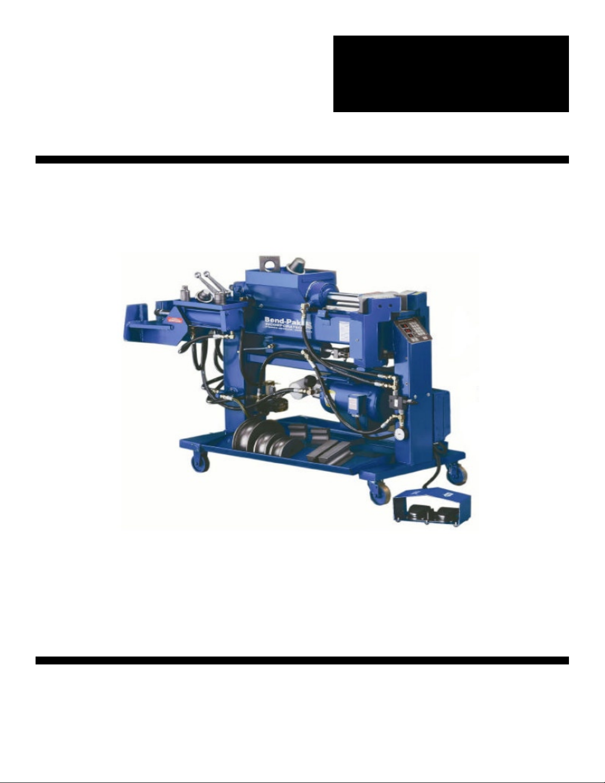
DEFINITION OF TERMS
The following definitions explain the major components
and operating features of your machine. The RIGHT,
LEFT, and REAR sides of the bender are relative to the
FRONT of the machine where all bending is performed.
BENDER- The whole machine including all end
finishing components.
BODY- The main 6” x 6” tubular structure that sits
horizontal to the floor and is located just below the top
cylinder.
SWAGER OR SWAGER BOX- The expanding/flaring
unit located to the rear of the bender which utilizes
pipe collars in conjunction with bullet shaped expander/
forming dies to perform a variety of tube end finishing.
INTERNAL EXPANDER- The expanding/flaring unit
located to the rear of the machine that utilizes seg-
mented expander dies. These “segment sets” are expand-
ed by the means of a tapered arbor pulled through their
center. This style of end finishing is usually required with
shorter pieces of tubing such as muffler nipples which do
not allow the use of a collar.
TOP CYLINDER- The main hydraulic bending cylinder
located at the top of the bender. It's primary function is to
activate movement of the radius dies.
BOTTOM CYLINDER- The hydraulic cylinder located
just below the body of the bender. It's primary function is
to apply resistance pressure to the back shoes as the
radius die pushes through.
RESERVOIR-The rear vertical leg that contains the
hydraulic oil.
FRONT UPRIGHT- The front vertical leg.
BENDER MODELS
There are nine different bender models available.
1000-BL 1000-BAS 1000-BA
1302-BL (Blue-Bullet) 1302-BAS 1302-BA
1502-BL 1502-BAS 1502-BA
The following is a brief description of their controls and
operating features. The model nomenclature consists of a
number (1302) followed by letters BA. The numbers des-
ignate what style frame assembly is used while the letters
signify the control features.
FRAME CONFIGURATION
1000 Series- A machine capable of bending only. Does
not come with any end finishing capabilities.
1302 Series- A machine capable of bending and end
finishing. Equipped with both swager and internal
expander. A double-ended hydraulic cylinder is used for
both end finishing functions. The end finishing assembly,
(the swager and internal expander) is positioned
“cross-wised” on the rear of the machine.
6 Bender Operation Manual
Overhead view of Model 1302
Side view of Bender showing major components.
7 Bender Operation Manual Bender Operation Manual 7
1502 Series- A machine capable of bending and end fin-
ishing. Equipped with both swager and internal expander.
Individual hydraulic cylinders are utilized for both end fin-
ishing functions. The swager and internal expander are
positioned at the rear of the machine, one on each side
and are positioned parallel with the main body.
CONTROL FEATURES
BL or BLUE-BULLET Models- A hydraulic control valve
is located at the front of the machine at knee height that
allows the operators to manually control the machine with
their leg. A degree plate is mounted up front that shows
proper bend depths. This model does not
incorporate any automatic bending features.
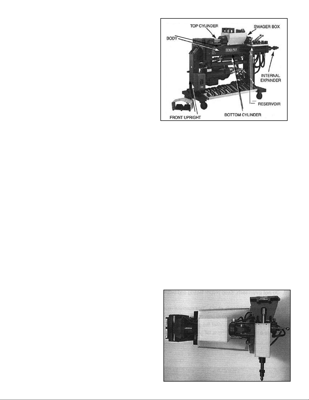
BAS Models- These models have two different control
modes. An electric foot switch assembly for manual bend-
ing operations and a three-button control board for auto-
matic functions. The degrees of bends are shown on a
degree plate mounted near the front of the machine which
also incorporates an adjustable slide pointer that can be
set to any desired bend depth. The control board consists
of three colored buttons; GREEN, BLUE and RED; each
with its own operating functions. If you choose to use the
machine in the automatic mode, you would simply set the
pointer to 90 degrees for example, then press the GREEN
button. At this time the bending head would activate and
the radius die would begin to move forward. After the
desired bend depth has been reached, the machine would
automatically initiate the retract sequence that returns the
die to the original
starting position. The BLUE button is for automatically
returning the die to the original starting position while the
RED button is an emergency stop control. The electric foot
switches will override the three button controls.
BA Models - These models have two different control
modes; an electric foot switch assembly for manual bend-
ing operations and a digital control board for automatic
functions. The digital control board eliminates the depth of
bend scale and replaces it with a digital readout labeled
“DIE ANGLE”. It also offers the user the capability to “pro-
gram” certain bend depths in a desired sequence. When
the power is turned off, all memory is erased. Once a bend
depth is programmed into memory the number appears in
a L.E.D. window labeled “SET ANGLE.” The bend
sequence is initiated by pressing the “AUTO” button. At
this time the die moves forward and upon reaching the
desired bend depth immediately retracts to the original
starting position. An emergency “STOP” button pauses
the machine at any time, and an additional auto “REVERSE”
button activates the return sequence. The electric foot
switches will override the digital controls.
INSTALLING THE
ELECTRICAL PLUG
Before installing a plug on the end of the power cord it is
important to check for proper voltage, phase, and amp
requirements. The tag attached to the end of the power
cord, or the motor identification plate will show this
necessary information. Due to the high amps and voltage
required to operate this machine at long durations, it is
recommended that you DO NOT USE AN EXTENSION
CORD LONGER THAN 15 FEET. This motor must be
grounded. The GREEN wire is for ground only. All wiring
should be done by a certified electrician only. Damage
to the motor caused by improper wiring is not covered
under warranty.
Overhead view of Model 1502
Three button control
Digital
control
board
D.O.B. Plate
TURNING YOUR NEW
BENDER ON
1. Plug the power cord into a receptacle closest to the
available circuit panel. IF SMOKE APPEARS OR
SHORTlNG OCCURS, DlSCONNECT
IMMEDIATELY! RE-CHECK ALL CONNECTIONS.
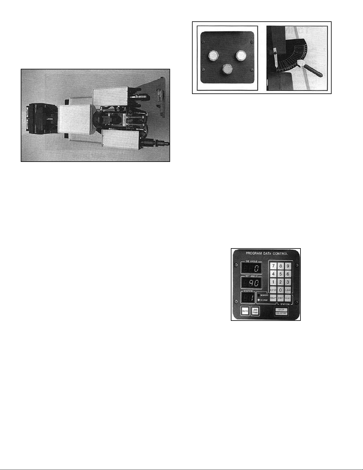
2. After the bender is plugged in, turn the machine on
by depressing the “ON” button located on the lower
right-front side of the machine. IF SMOKE
APPEARS OR SHORTlNG OCCURS,
DlSCONNECT IMMEDIATELY! RECHECK ALL
CONNECTIONS.
3. Let the bender run for approximately five minutes
without operating the controls.
4. At this time, it is necessary to install all control han-
dles by properly connecting the linkages as shown.
5. After the bender is warmed up, retract the radius
die that contains the sample tube. On automatic
models do this by depressing the left foot switch.
On Blue-Bullet or manual models activate the knee
control valve by moving the handle to the right.
6. IF THE RADIUS DIE DOES NOT MOVE,
CONSULT THE FACTORY.
7. After the radius die has completely retracted,
remove the sample tubing that is in place.
8. Bring the radius die forward by depressing the right
foot switch or by moving the manual control valve
handle to the left.
9. Advance the radius die to l00 degrees then retract
fully. Repeat this sequence for at least five times.
The bending die may move erratically for the fIrst
few cycles due to air trapped in the lines. This is
normal. The air will dissipate after use. Do not try to
“crack” a line to help the air escape.
10. At this time check for any possible leaks that could
have developed during shipment. Tighten any
hoses that may have loosened.
11. Check the oil level by observing the sight gauge
located near the right-rear side of the machine. If
the oil level appears low, add oil now. (See page 32
for recommended hydraulic oils.)
12. Activate the swaging and internal expander cylinders
by depressing the control handles located at the rear
of the machine. Cycle the cylinders to their full extent
at least fIve times. Again, these cylinders may act
erratically until the air dissipates.
TOOLING
Find the packing list that accompanied your bender, item-
izing each tool that was to be included in your tooling
package. Double check the pieces you received with
those that were checked off. ALL THE TOOLS THAT
ARE CHECKED OFF IN THE “SHIPPED” COLUMN DID
SHIP WITH YOUR BENDER. If you cannot fInd a certain
piece that you feel should be with the shipment, check
with the freight carrier or observe the packing list and
check the back ordered column. If a certain item is back
ordered it will be automatically forwarded to you. A
description of tooling is listed below.
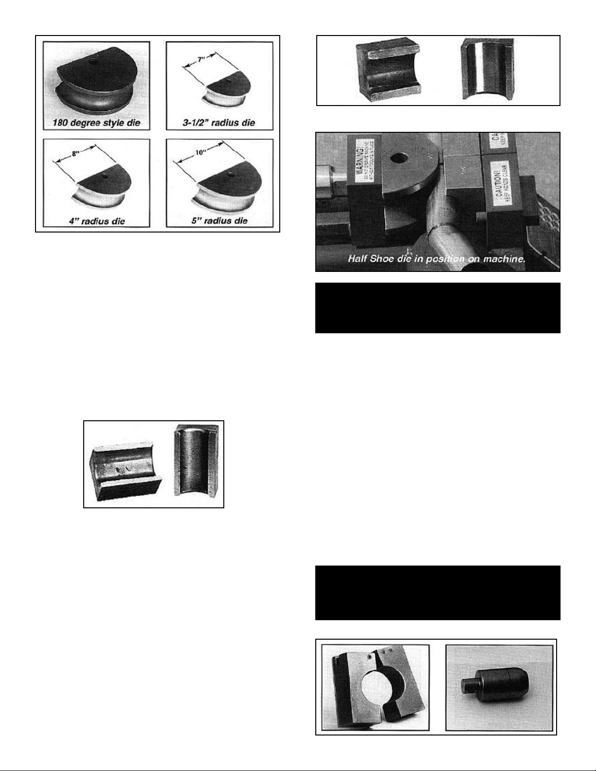
RADlUS DIES- These dies which are commonly referred
to as the “bending dies” come in different radii and tubing
sizes. Each die is machined and sized according to tubing
diameters. The proper tube size is stamped on the top of
each die. 112 represents 1-1/2” tubing, 134 represents
1-3/4” tubing etc. The radius dies are available in three
standard radii, 5”, 4” and 3-1/2”. Each standard radius die
represents half of a circle or diameter. 180 degree dies
are also available which represent three quarters of a
circle and allow the tubing to “wrap” around farther
although the radii are the same.
8 Bender Operation Manual
Control handle linkage assembly
Oil sight gauge
Electrical On / Off switch box
9 Bender Operation Manual
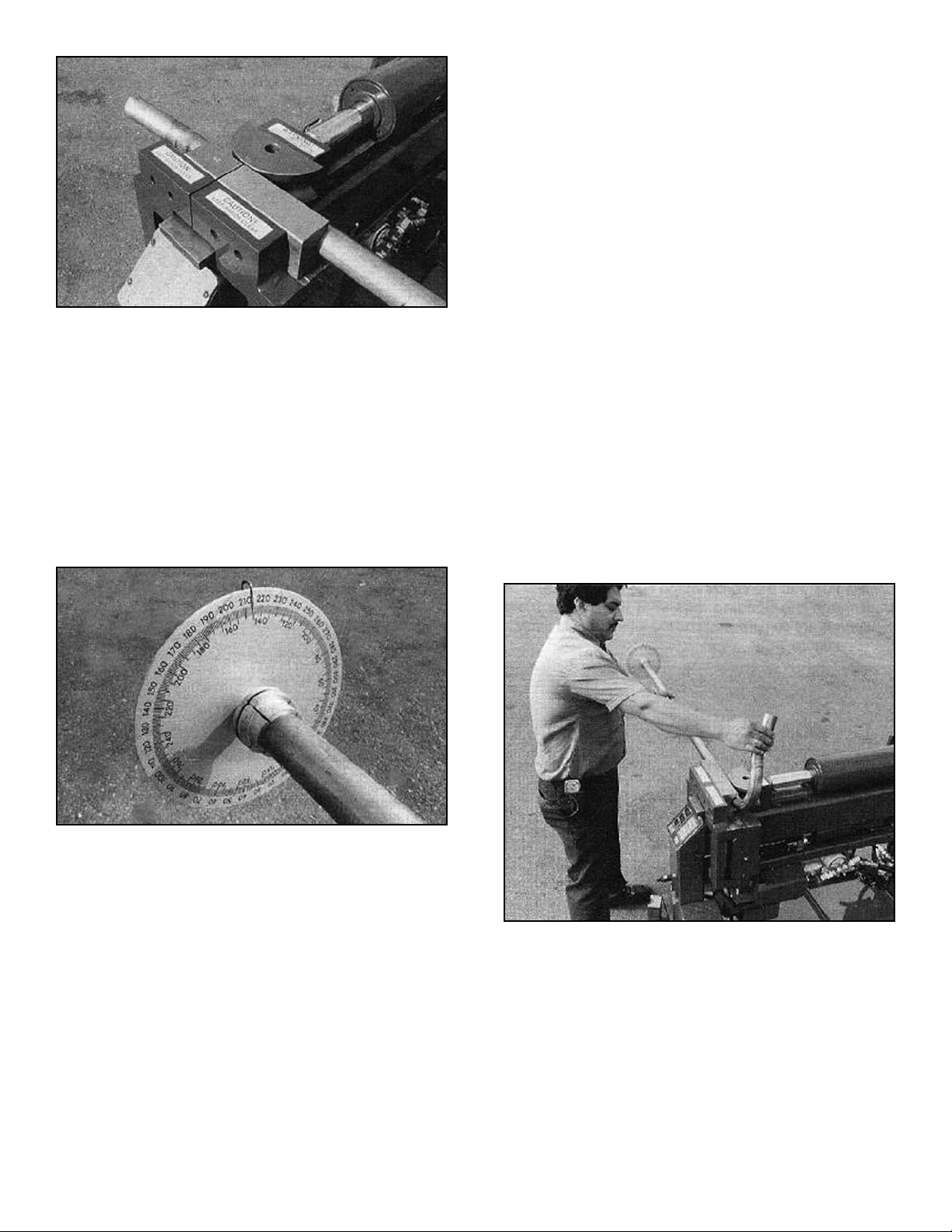
BACK SHOES- Back shoes, which are commonly referred
to as wiper dies come in pairs and are used together with
the radius dies during the bending process. These dies
play an important part as their primary
purpose is to form the outside radius of the bend. These
dies are used to clamp or retain the pipe as it is wrapped
around the radius die. Each back shoe is machined and
sized according to tubing diameter. The proper tubing size
is stamped on the top of each back shoe.
NOTE:
Back shoes should be kept clean and lightly oiled.
Never use the bender without back shoes in
place. Never use the bender as a vice or a press.
HALF SHOES AND THREE QUARTER SHOES Half
shoes and three quarter shoes do not come in pairs. Only
one is required. Half shoes are exactly half the length of a
standard back shoe and three quarter shoes are three
quarters the length. These smaller shoes are required
when an upcoming bend is less than ten inches from an
existing bend. The half/three quarter shoe will be used in
conjunction with the back shoe and placed only on the
side where the full back shoe may interfere with the
upcoming bend. (Details for the proper use of these tools
are explained in the BENDING section.)
NOTE:
Half shoes and three quarter shoes must be used
with radius dies and back shoes of the same
corresponding size.
HAC's & STED's- HAC's are Commonly referred to as
“adapter collars” while the STED's are referred to as “solid
expander dies”. HAC's are used to hold or clamp the tub-
ing in place when performing end-finishing Operations or
when using the STED's. These “adapter collars” are heat
treated which causes the inside threads or “teeth” to
become brittle. Because of this, these “teeth” have the
tendency to chip during normal use. This is normal and will
have no effect on their performance. The STED's or “solid
expander dies” are used to expand the tubing to exact
inside diameters and are also used to create male ball
expansions. Both tools are stamped and marked with their
appropriate tubing sizes. (Details on the proper use of
both tools is explained in the END FINISHING section.)
NOTE:
Keep collars free of debris and build up. Use a
wire brush periodically to clean the inside
threaded area. Keep all tooling lightly oiled.
Bender Operation Manual 9
Back shoe dies
CAUTION!
KEEP HANDS CLEAR when using all the tools
described in this manual. Improper use of these
tools may result in serious bodily harm
CAUTION!
All tooling described in this manual is heavy!
HANDLE WITH CARE. Always wear steel toe boots
when operating bender.
Adapter Collars STED Expander dies
Half Shoe Three Quarter Shoe
END-FINISHING TOOLS - A variety of end finishing tools
are available that perform different functions. Not every
tool is included with your tooling package. If you are
unsure as to what was included, please consult your dis-
tributor or review the delivery receipt and invoice. Each
tool is marked with the appropriate size.
HPF-300 - A tool for making 45 and 90 degree flanges on
pipe ends. Usually for manifold connections.
DD-134/212- A tool for doming pipe ends or making male
ball expansions when used in conjunction with the male
ball expanders.
DD-134/212 & BFED-200/214 - Tools for flaring pipe ends
to make female ball expansions. Each tool is “stepped”
and has the ability to flare two different sizes. The BFED-
134/214 is used for tubing sizes 1-3/4” and 2-1/4” while
the BFED-200/212 is used for tubing sizes 2” and 2-1/2”.
B-212- A tool used for making male ball expansions on
2-1/2” pipe ends.
CFT-200 & CFT-214 - Tools for making manifold flanges
on 2” and 2-1/4” pipe ends. Not included in standard
tooling packages.
REDUCING TOOLS - Reducing tools are used for
reducing or “shrinking” pipe ends to exact outside diame-
ters. Each tool is marked with the appropriate size. It is
important to understand that the size marked on the tool
will be the size that the tubing will be reduced down to. For
example, a tool marked 200 will reduce 2-1/4” tubing
down to 2” O.D. and a tool marked 214 will reduce
2-1/2” tubing down to 2-1/4” O.D. Not included in
standard tooling packages.
HCT-214/212 - This tool is for making header flanges or
“collectors” on 2-1/4” and 2-1/2” pipe ends. This
eliminates the need to purchase a collector when
installing header type manifolds.
Not included in standard tooling packages.
HSRO- A hand held pipe reshaping tool that is used for
reshaping pipe ends while the tubing remains on the
vehicle. By tapping the tool with a hammer or mallet the
tool can be used to reshape pipe ends. Can be used inter-
nally or externally by simply reversing the tool. Not avail-
able in standard tooling packages.
BENDING PLUGS - Bending plugs are used to contain
the shape of pipe ends during the bending process when
the radius die comes in close proximity to the pipe end.
Once the bend is completed, the bending plug is removed.
Not included in standard tooling packages.
10 Bender Operation Manual
CAUTION!
DO NOT attempt to use these tools unless you have
read and fully understand the
“Swaging and End Forming” section.
CAUTION!
ALWAYS wear protective safety glasses or goggles
when using this machine
IMPORTANT NOTICE
Installing headers on any motor vehicle is illegal in
most states and may violate the 1990 Clean Air Act.
Consult the EPA at (202) 260-7645 for questions
regarding the installation of any aftermarket perfor-
mance product that may alter vehicle emissions.
HPF-300 DD-134/212
Reducing Tool HCT-214/212
HSRO Bending Plug
BFED-134/214 BFED-200/212
B-212 CFT-200
11 Bender Operation Manual
SEGMENT EXPANDERS - Segment expanders or “seg-
ment sets” come in a variety of sizes and shapes, each
performing it's own distinct function. Segment sets are
used for short pieces of tubing or when the tubing end is
minimized due to an existing bend. They can also be used
to expand tubing that is deformed in such a manner that
will not permit use of the swager expander. Segment sets
are used in conjunction with an arbor or mandrel. All seg-
ment sets are identified by grooved rings located at the
bottom as described on the following chart. There are
four different types of segment sets available; STANDARD
SEGMENT SETS, MANIFOLD FLANGE SEGMENT
SETS, BALL-JOINT SEGMENT SETS, and FLARE
SEGMENT SETS.
STANDARD SEGMENT SETS - These segment sets are
used to make straight expansions on tubing ends and are
found in all standard tooling packages.
MANIFOLD FLANGE SEGMENT SETS - These segment
sets are used to make donut-type manifold flanges on tub-
ing ends. They are available in five sizes; 1-1/4”, 1-1/2”,
2”, 2-1/4”, and 2-1/2”. All manifold segment sets are used
in conjunction with limit rings. Not included in standard
tooling packages.
BALL-JOlNT SEGMENT SETS - These segment sets are
used to make ball-joint expansions on tubing ends. They
are available in three sizes; 2”, 2-1/4” and 2-1/2”. Not
included in standard tooling packages.
FLARE SEGMENT SETS - These segment sets are used
to make 45 degree flares on tubing ends. Three different
sets are available that work on tubing sizes 1-1/2” -
2-1/2”.
Not included in standard tooling packages.
NOTE:
Keep segment sets and arbor well greased.
The ARBOR which is pulled through the center of the seg-
ment sets is available in two sizes. The HSA-114 is an
arbor used exclusively for 1-1/4” and 1-3/8” tubing while
the HSA-112 is used for tubing sizes 1-1/2” through 3”.
Bender Operation Manual 11
WARNING!
1. Always remove excess tooling from swager area
before using internal expander.
2. To avoid breaking tooling ALWAYS use proper
segment sets with appropriate tubing size.
3. NEVER stand in front of arbor when operating
internal expander.
HSA-112 Arbor HSA-114 Arbor
DIGITAL CONTROL
OPERATIONS.
“BA” MODELS.
Read each of the following sections carefully before
attempting any operation of this unit. All “BA” models are
equipped with a computer microprocessor that allows
minor storage and recall of certain bend data. It also gives
the user the ability to bend automatically or manually.
DESCRIPTION OF
CONTROLS:
SELCT - Selects KEYPAD or MEMORY functions.
CLEAR - Clears the SET ANGLE.
ENTER - Enters the numbers displayed in SET ANGLE
into memory. (Only when KEYPAD is lighted.)
STEP - Advances station number display.
RESET - Resets station number back to one.
AUTO - Starts automatic cycle.
JOG/FWD - Press and hold to advance radius die manu-
ally. Release button and all forward motion will stop.
Overrides AUTO button.
STOP/REVERSE (Also, EMERGENCY STOP) -
Press to stop forward movement of radius die. Press
again to reverse, then again to stop.
SET ANGLE WINDOW - Displays depth-of-bend degrees
programmed for the next bend.
DIE ANGLE WINDOW - Continuously displays the degrees
of bend as the radius die moves forward.
STATION WINDOW - Shows the position or station num-
ber that a particular bend depth has been programmed
into.
REMOTE FOOT SWITCHES - Used for manual opera-
tion. The right foot switch advances the radius die while
the left foot switch retracts it. Either foot switch will also
serve as an emergency stop.
12 Bender Operation Manual
STOP!
Before any attempt is made to operate this machine
it is important that you have read and fully under-
stand all operating instructions described in this
manual.

13 Bender Operation Manual
NOTE:
Practice the following bending steps without
tubing and initiate a few “dry runs” until you
understand the operating features.
USING THE REMOTE FOOT SWITCHES OR AUTO
BUTTON - When using a card system or bending a pipe,
you are not required to use the “Memory” function. Some
operators will use the memory function only when multiple
pipes are to be bent. The most popular method will be
manual or semi-automatic. When KEYPAD is lighted, the
machine will operate manually using the remote foot
switches or JOG/FWD button or semi-automatically,
performing one bend at a time using the AUTO button.
The actual depth-of-bend degrees will continuously appear
in the DIE ANGLE window any time the machine is
running. To manually operate the bender, depress the
right foot switch to advance the radius die and the left one
to retract it. The foot switches will always override the
automatic controls. When using the foot switches, the
radius die will NOT stop at the SET ANGLE.
To bend one bend at a time using the AUTO button,
follow these step-by-step instructions.
1. Turn the bender on and depress the SELCT button
to illuminate the KEYPAD light.
2. Find out what degree of bend is required and enter it
by depressing the appropriate number keys.
This number will then appear in the SET ANGLE
window. If you make a mistake and improperly
enter the wrong number, simply clear the SET
ANGLE by depressing the CLEAR button then
re-enter the proper information.
3. With the KEYPAD light illuminated, disregard any
numbers that may appear in the STATION window.
4. After installing a matched die set, position the tubing
so that you can begin bending.
5. Check your “circle-of-swing” for allowable clearance.
6. Depress the AUTO button to initiate the semi-
automatic cycle.
7. At this time the radius die will begin to move forward
until it reaches the designated depth-of-bend dis-
played in the SET ANGLE window. The retract
sequence will then automatically initiate, reversing
the radius die until it is fully retracted.
8. For the remaining bends, move the pipe over until
the next bend position or “center mark” is centered
between the back shoes. Repeat steps 5-7.
9. After all bends are completed, cut off the tubing end
to match the existing pipe or master.
PROGRAMMING THE DIGITAL BOARD- Follow these
step-by-step instructions to properly utilize the MEMORY
feature. The PROGRAM DATA CONTROL board stores
bend depths only. All data will be cleared once power is
turned off. The memory feature can be used when bend-
ing multiple or individual pipes The following instructions
illustrate how to properly enter the data which is shown
on the program cards.
1. Press the SELCT button to illuminate the KEYPAD
light.
2. Press the RESET button to return the STATION
window to number one.
3. Using your program card, enter the first degree of
bend shown in the BEND-DEPTH column. Press the
appropriate number keys to display the recommended
bend depth in the SET ANGLE window. Now press
the ENTER key. You have just entered the first bend
depth in station number one.
4. Press the STEP button to change the station to display
the number “2”.
5. Using your program card, enter the second depth of
bend by pressing the appropriate number keys. The
number should appear in the SET ANGLE window. If
the information is correct press the ENTER key. You
have now entered the second bend depth in station
number two.
Bender Operation Manual 13
WARNING!
1. Either foot switch will act as an EMERGENCY
stop.
2. NEVER operate the remote electric foot switches
in or around water or damp areas.
3. If the foot switch cords become frayed or
damaged
in any way, discontinue use until they are properly
repaired.
4. ALWAYS disconnect power cord before making
any electrical repairs.
CAUTION!
KEEP HANDS CLEAR while dies are in motion.
Familiarize yourself with the EMERGENCY STOP
button and its operation. NEVER place hands near
bending area or any pinch points when motor is
running. ONLY TRAINED PERSONNEL should be
near machine when it is in operation.
CAUTION!
If operating controls are malfunctioning,
discontinue use immediately. DO NOT attempt to
operate machinery until controls have
been repaired.
6. Repeat these steps until all depth-of-bends have
been entered. Always remember to press the
ENTER key prior to advancing to the next station.
7. Now press the SELCT key to illuminate the MEMORY
light.
8. Press the RESET button. This will change the
STATION window to number “1”.
9. To double check the data that has been entered,
press the STEP key to advance the stations through
their appropriate sequence. Review the data that has
been entered. If you reach a particular station that is
incorrect, press the SELCT key to illuminate the
KEYPAD light, the SET ANGLE will show zero at this
time then press the appropriate number keys and
retain the data by depressing the ENTER key. After
correcting the improper data, press the SELCT button
to illuminate the MEMORY light and the RESET key
to reset the STATION window. Review the information
once again.
NOTE:
In order to store data into program memory
the KEYPAD light must be illuminated.
Entered data will not be shown in the SET
ANGLE window until the MEMORY light is
illuminated.
THREE-BUTTON
CONTROL OPERATIONS
“BAS” MODELS
Read each of the following sections carefully before
attempting any operation of this unit. All “BAS” models
are equipped with a three-button control board that con-
trols the semi-automatic bending function. In addition to
the three-button control board, all “BAS” models are
equipped with a remote foot switch for manual operation.
DESCRIPTION OF
CONTROLS:
NEVER HOLD IN COLORED CONTROL BUTTONS! -
To properly operate the colored control buttons, quickly
press and release. By holding the colored control buttons
in, damage to the machine and/or components may
result.
GREEN BUTTON - Activates the automatic bending
cycle. After pressing the GREEN button, the radius die
will move forward until the desired depth-of-bend is
reached then automatically retract until the die is
returned to the original starting position.
BLUE BUTTON - Automatically returns or retracts the
bending die to the original starting position. NEVER hold
the BLUE button in when retracting the bending ram.
RED BUTTON - Serves as an “Emergency Stop” button.
Automatically stops all movement of the bending die dur-
ing the automatic cycle.
REMOTE FOOT SWITCHES - Used for manual opera-
tion. The right foot switch advances the radius die to start
the bending process. The left foot switch retracts the
radius die. Either foot switch will also serve as an emer-
gency stop.
NOTE:
Practice the following bending steps without
tubing and initiate a few “dry runs” until you
understand the operating features.
USING THE “AUTO-STOP” DEPTH-OF-BEND FEATURE -
The “Auto-Stop” slide pointer is attached to the depth-of-
bend degree plate and stops the radius die at pre-set
bend depths. The “Auto-Stop” feature works with either
the GREEN automatic control button or the remote foot
switches.
14 Bender Operation Manual
WARNING!
1. Either foot switch will act as an EMERGENCY stop.
2. NEVER operate the remote electric foot switches
in or around water or damp areas.
3. If the foot switch cords become frayed or damaged
in any way, discontinue use until they are
properly repaired.
4. ALWAYS disconnect power cord before making
any electrical repairs.
5. If any operating controls are malfunctioning,
discontinue immediately.
15 Bender Operation Manual
To use the three-button automatic controls, follow these
simple instructions.
1. Position the “Auto-Stop” pointer at the desired depth
of bend.
2. Position the tubing at the appropriate bend mark.
3. Check your “circle-of-swing” and prepare to begin
bending.
4. Press the GREEN control button.
5. At this time the radius die will advance until the
desired depth-of-bend is reached, then, retract to the
original starting position.
6. Be prepared to support the tubing as it is released
from the dies.
USING THE REMOTE FOOT SWITCHES - The remote
foot switches are used for manual bending functions.
When using the foot switches for manual operation it is
best that you position the “Auto-Stop” pointer out of the
way or at 180 degrees so that it does not interfere. If you
want to use the foot pedals in conjunction with the “Auto-
Stop” pointer, position the pointer at the desired bend
depth and proceed by pressing the RIGHT foot switch
until the radius die stops at the pre-set bend angle.
Press the LEFT foot switch to retract the radius die.
Always be prepared to support the pipe as it is released
from the dies.
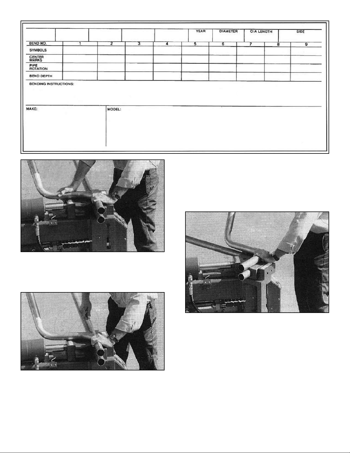
OPERATING THE MANUAL
KNEE CONTROL.
“BL” / BULLET MODELS
Read the following section completely before attempting
any operation of this unit. All “BL” models are equipped
with a hydraulic control valve mounted at knee height
that allows the user to operate the machine manually
with their leg. A degree plate with pointer is mounted
near the front of the machine that gives the user accu-
rate bend depths. “BL” models are not equipped with any
automatic features.
To operate the manual control valve, move the handle to
the left or the plunger down to advance the radius die.
The handle must be fully engaged to properly control
radius die movement.
To retract the radius die, move the handle to the right (or
plunger up) to return to the original starting position.
Always be prepared to support the pipe as it is released
from the dies.
OPERATION NOTE / BL MODELS:
If the operating control handle is pressed half way or par-
tially down during the bending operation, the radius die
may slow down or even retract slightly. To keep the
bending die at a controlled speed you must fully depress
the valve handle. If you wish to advance the radius die a
few degrees only, instead of easing the handle down, try
“tapping” the handle.
BENDING OPERATIONS
There are basically two styles of bending that can be per-
formed on your new bender. The first is PROGRAM CARD
BENDING which requires the use of PROGRAM CARDS
that contain instructional data for specific applications.
The second is PATTERN BENDING which is the most
popular method and duplicates pipes by using an existing
pipe or wire pattern as a master.
USING THE PROGRAM CARDS - The Program Card
System contains bending data for specific applications.
The following instructions define each section of the card.
It is important that you read the entire card carefully before
attempting to bend. Due to the many cards and applica-
tions covered, there may be some inaccuracies. No
responsibility is assumed by the manufacturer for any
consequences arising from inaccuracies found on the pro-
gram cards.
Look up the card number in the appropriate reference
catalog. Exhaust pipes numbers start with the letter “E”
and tail pipes numbers start with the letter “T”.
Bender Operation Manual 15
CAUTION!
Be alert at all times. NEVER place hands near
bending area or other pinch points
when motor is running.
Take down the number of the pipe to be bent, find and
remove it from the deck. Remember to place a marker of
some type in its place. The cards are filed in numerical
sequence by the number shown on the top left section of
the card. Only the last four digits shown are in sequential
order. Some cards start with a prefix such as T3 or T5 then
are followed by a four digit number. ALWAYS disregard the
prefix and follow the last four digits only.
DEFINITION OF CARD
SECTIONS:
YEAR - Gives the year of the vehicle that the card pertains
to.
DIAMETER - The original equipment factory recommend-
ed tubing diameter for that particular vehicle,
O/A LENGTH - Overall length of tubing required for that
particular pipe. Also referred to as the cut-off point.
SIDE - When more than one section of tubing is required
for a particular card number, this section shows if it is the
front, rear, left or right side.
SYMBOLS - Shows certain symbols that pertain to indi-
vidual bending instructions that are explained in greater
detail in the BENDING INSTRUCTIONS section. The
symbol section also includes the descriptive “F” and “R”
symbols that indicate how the pipe fits on the vehicle. “F”
means front and “R” means rear.
CENTER MARKS - Refers to the actual locations or mea-
surements that the bends will be located.
PIPE ROTATION - Shows in degrees what the correct
pipe rotation (or plane) is for each bend.
BEND DEPTH - Shows in degrees what the correct bend
depth is for each bend.
MAKE - Gives the make of the vehicle. Chevrolet, Pontiac,
Ford, Chrysler, etc.MODEL - Gives descriptive factors
such as the model, engine and frame size.
BENDING INSTRUCTIONS - Shows what radius die will
be used in addition to other tooling such as half shoes
and three quarter shoes. Also gives instructions on
reversing and certain end-fInishing requirements. Not all
applications will be shown on the card.
Follow these step-by-step instructions to bend the pipe
for the card shown above.
1. Select the proper tubing size for the application as
called for in the DIAMETER SECTION of the card.
(See Recommended Tubing Chart on page 48) Wipe
tubing to remove excess oil.
2. Install the correct radius die as called for in the
BENDING INSTRUCTION section. Two back shoes
are required unless otherwise specifIed. Place tubing
in the bender between the back shoes and radius die
with the greater portion of the tubing extending out
the LEFT side of the bender. This is necessary so
that you can mark the tubing with the appropriate
CENTER MARKS shown on the card.
3. Engage the bending dies until the pusher
block springs are compressed and the tubing is held
fIrmly. Carefully control the advancement of the
radius die so as not to dent or bend the tubing at this
time. (See figure 1-A)
16 Bender Operation Manual
Sample card layout to be used in conjunction with bending instructions.
Figure 1-A
17 Bender Operation Manual
4. Using the program card, refer to the section marked
CENTER MARKS for the list of measurements in
inches where the different bends will be made. Each
CENTER MARK is measured from the left end of the
tubing. Mark and number the CENTER MARKS on
the tubing using a crayon or felt tip pen. The last
mark you make should be the cut off point shown in
the O/A LENGTH section. DO NOT CUT THE TUBING
at the last center mark until the final bend is
made. (See figure 1-B.)
5. Disengage the dies and reposition the tubing so that
the greater portion is now extending out the RIGHT
side of the bender and the first CENTER MARK is
lined up with the center of the two back shoes.
6. Engage the bending dies until the pusher block
springs are compressed and the tubing is held firmly.
(See figure 1-C)
7. Rotate the tubing so that the weld seam on the tubing
is facing up or at the 12 o-cIock position. The push-
er block springs are designed to hold the tubing
secure but still allow rotation of the pipe. Install the
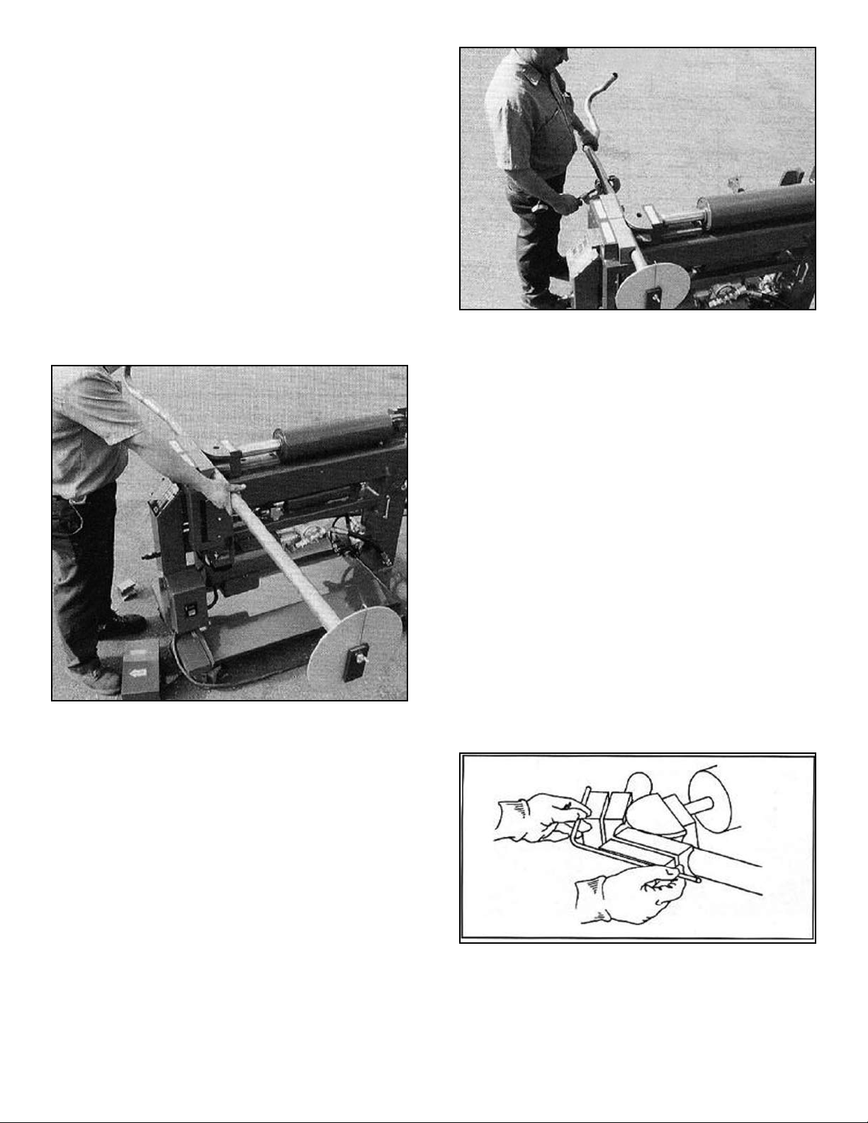
rotation dial on the RIGHT end of the tubing. Loosen
the butterfly nut if necessary and insert the segmented
expander inside the tubing end. Tighten the butterfly
nut until the rotation dial is secure.
9. With the rotation dial properly installed, rotate the
degree plate not the tubing so that the pendulum
pointer is showing ZERO. Make sure the butterfly nut
remains tight.
10. You are now ready to make your first bend. At this
time you may program your depth-of bends on the
digital board as described in the DIGITAL CONTROL
OPERATION section; position the depth-of bend
pointer on BAS models; or elect to use the electric
foot switches or manual knee control valve. For
beginning operators we suggest that manual controls
are used until you become more familiar with the
operating features of your machine
11. As described in the BEND DEPTH section of the
card, advance the radius die to 17 DEGREES then
retract the die to the original starting position. The
rotation dial should still show ZERO at this time.
12. Review the SYMBOLS section of the card and check
for any special instructions. On bend number two
you will notice that a HALF SHOE is called for. Install
the HALF SHOE now. Unless a special instruction is
given to change the radius size, you will continue to
use the 3-1/2” radius through the remaining bends.
NOTE:
Always position the HALF SHOE or THREE QUARTER
SHOE on the same side as the previous bend.
13. For the second bend, slide the tubing to the LEFT so
that the second CENTER MARK is lined up with the
center of the shoes.
(See figure 2-B.)
NOTE:
The weld seam on the tubing should be directly in line
with the ZERO mark at this time. (See figure 2-A)
Bender Operation Manual 17
CAUTION!
Before advancing the radius die check your
circle-of-swing for allowable bending clearances.
Figure 1-B
Figure 2-A
Figure 1-C
14. With the HALF SHOE in place and the secondCENTER
MARK lined up at the center of the shoes, advance
the radius die forward until the pusher block springs
are compressed and the tubing is held securely.
Carefully control the advancement of the radius die
to prevent denting or bending of the pipe at this time.
15. Now, rotate the tubing not the dial so that the pendulum
pointer or dial indicator points to the proper setting as
shown in the PIPE ROTATION section of the card. In
this case the PIPE ROTATION will be 147 degrees.
ALWAYS use the inside set of numbers. (See figure 2-C)
NOTE:
The rotation dial is equipped with two scales.
The standard scale which is used for all
regular bending operations is positioned to the
INSIDE of the dial. The OUTSIDE scale is
used for bending “mirror images” or opposite
side pipes.
16. With the rotation dial properly set at 147 degrees and
the center mark lined up, advance the radius die to
11 degrees as shown on the card. Retract the die to
the original starting position.
17. Review the SYMBOLS section of the card and check
for any special instructions. On bend number three
you will notice that a REVERSE / USE HALF SHOE
is called for.
The ROTATION DIAL degree plate MUST NEVER be
moved after bending has begun.
ALWAYS be prepared to support the tubing as it is released
from the dies to prevent it from hitting the ground. If the dial
is accidentally moved during the bending process,
re-position the dial so that the
ZERO mark is located at the weld seam of the tubing, or
return to the previous bend and position the pendulum point-
er to the degrees required for that particular bend.
18. lf a bending instruction calls for a REVERSE, remove
the tubing and position the ROTATION DIAL on the
LEFT SIDE of the machine. Be careful not to move
the ROTATION DIAL degree plate during this process.
NOTE:
When a REVERSE is called for, the rotation dial
will be positioned on the LEFT side for that
bend only. If the SYMBOL section shows a
REVERSE again for the following bend, the
rotation dial MUST remain on the LEFT side. If
no REVERSE is called for, the rotation dial
MUST be returned to the RIGHT side.
19. For bend number three, REVERSE the tubing and
install the HALF SHOE now. (See figure 3-A)
20. With the HALF SHOE in place and the third CENTER
MARK lined up at the center of the shoes, advance
the radius die forward until the pusher block springs
are compressed and the tubing is held securely.
21. Rotate the tubing not the dial so that the pendulum
pointer or dial indicator points to the proper setting as
shown in the PIPE ROTATION section of the card. In
this case the PIPE ROTATION will be 250 degrees.
USE THE INSIDE set of numbers. Advance the radius
die to 7 degrees.
18 Bender Operation Manual
Figure 2-C
Figure 2-B
Figure 3-A
19 Bender Operation Manual
22. Review the SYMBOLS section of the card and
check for any special instructions.
23. On bend number four you will notice that a
REVERSE USE HALF SHOE is again called for.
Keep the ROTATION DIAL on the LEFT side for this bend.
24. Advance the radius die forward until the pusher block
springs are compressed and the tubing is held securely.
25. Rotate the tubing so that the pendulum pointer or
dial indicator points to 260 degrees.
26. Advance the radius die to 35 degrees then retract
the die to the original starting position.
27. Review the SYMBOLS section of the card and check
for any special instructions for bend number five.
28. On bend number five no special instructions are
shown. In this case, return the ROTATION DIAL to
the right side and install the full BACK SHOE. A
HALF SHOE is not required for this bend.(See figure 3-B.)
29. Advance the radius die forward until the pusher block
springs are compressed and the tubing is held securely.
30. Rotate the tubing so that the pendulum pointer or
dial indicator points to 223 degrees.
31. Advance the radius die to 18 degrees then retract
the die to the original starting position.
32. Review the SYMBOLS section of the card and check
for any special instructions for bend number six.
33. On bend number six no special instructions are shown.
34. Advance the radius die forward until the pusher block
springs are compressed and the tubing is held securely.
35. Rotate the tubing so that the pendulum pointer or
dial indicator points to 277 degrees.
36. Advance the radius die to 9 degrees then retract the
die to the original starting position.
37.You are now finished bending the pipe. Remove the
ROTATION DIAL and cut the tubing end off at the
last O/A mark. (See figure 3-C.)
38. Now check the BENDING INSTRUCTIONS section
and check for any END FINISHING requirements.
On this particular card, it calls for a FEMALE BUICK
BALL on the FRONT or “F” side of the pipe. See
page 12 for TYPICAL END FINISHING illustrations.)
PATTERN BENDING
To pattern bend, proceed as follows. In order to retain the
information for later use, save the information as described
below.
NOTE:
Use the blank program card found on the next page
as a master to make additional
copies for later use.
1. Select the proper tubing size and die set to do the
job. Try to match the radius size with that of the existing
pipe.
2. Place the tubing in the bender with the greater portion
of the tubing protruding out the right side of the
bender.
3. Place the master pattern (existing pipe or bent wire
on the top of the back shoes so that the first bend is
centered between the back shoes.
4. Adjust the tubing out the left side of the bender so
that the tubing end matches the length with that of
the master. (See figure 1-A) Secure the straight pipe
by advancing the radius die until the pusher block
springs compress.
Bender Operation Manual 19
Figure 3-B
Wire pattern being used as a master.
Figure 3-C
5. Using a measuring tape, measure the distance from
the end of the tubing to the center of the back shoes.
This is the measurement to the first bend and should
be recorded in the CENTER MARKS section of a
blank card. (See figure 1B)
6. Place the ROTATION DIAL on the far right end of the
straight tubing and secure by tightening the wing nut.
Center the ROTATION DIAL degree plate so that the
indicator points to zero. ALWAYS USE THE
NUMBERS CLOSEST TO THE CENTER OF THE
ROTATION DIAL. THE OUTSIDE NUMBERS ARE
FOR SPECIAL APPLICATIONS ONLY. Record the
rotation degree as zero for your first PIPE ROTATION.
7. You are now ready to make your first bend. Place the
first bend of the master pipe or wire flat on top of
the back shoes. Hold in this position. Gradually
extend the radius die forward until the gates start to
open and the tubing begins to bend. Continue
bending until the bend depth is equal to that of the
master. (See figure 1-C)
8. Look at the Depth-of-Bend plate or observe the DIE
ANGLE window. This is the depth or degrees of the
first bend. Record this information in the BEND
DEPTH section.
9. Retract the bending dies and slide the straight tubing
to the left. Place the tubing or master on top of the
back shoes so that the centerline of the second bend
lines up with the centerline of the back gates. Be
sure that the master lies perfectly flat.
10. Line up the second bend of the new pipe with the
second bend of the master. Be sure that the master
remains flat on top of the back shoes. Advance the
radius die until the pusher block springs are
compressed and the tubing is held securely. Make
any adjustments at this time. Your second bend is
now correctly located. (See figure 2-A)
20 Bender Operation Manual
Figure 1-A
Figure 1-B
Figure 1-C
(This blank card may be used to make additional copies)
This manual suits for next models
8
Table of contents
Other Bend-Pak Construction Equipment manuals


Popular Construction Equipment manuals by other brands

Plymovent
Plymovent KUA-160/H Series Installation and user manual

MULTILIFT
MULTILIFT Ultima S Flex User and maintenance manual

Komatsu
Komatsu Super D155AX-3 Operation & maintenance manual

Dragon Wholesaling
Dragon Wholesaling LF1000 user manual

MULTIQUIP
MULTIQUIP Mikasa MVH408DE Operation manual

Case
Case 2050M Stage IIIB Service manual


