Bender EDS460 User manual

Power in electrical safety
Operating Manual
EDS460/490 and EDS461/491
Insulation fault evaluators
Software version: EDS...-D: D234 V2.11 / D256 V2.12
EDS...-L: D234 V2.11 / D216 V2.12
TGH1394en/05.2007

Dipl.-Ing. W. Bender GmbH & Co.KG
Londorfer Str. 65 • 35305 Grünberg • Germany
Postfach 1161 • 35301 Grünberg • Germany
Tel.: +49 (0)6401-807-0
Fax: +49 (0)6401-807-259
E-Mail: [email protected]om
Web: http://www.bender-de.com
©Dipl.-Ing. W. Bender GmbH & Co.KG
All rights reserved.
Reprinting only with permission
of the publisher.
Subject to change!

Table of Contents
3
TGH1394en/05.2007
1. How to get the most out of this manual ...................................................... 7
1.1 How to use this manual ................................................................................. 7
1.2 Explanation of symbols and notes ............................................................. 7
2. Safety instructions ........................................................................................... 9
2.1 Intended use ...................................................................................................... 9
2.2 Qualified personnel ...................................................................................... 10
2.3 Safety information ........................................................................................ 10
2.4 Warranty and liability ................................................................................... 11
2.5 Guarantee ........................................................................................................ 12
3. System description ........................................................................................ 13
3.1 Features ............................................................................................................ 13
3.1.1 Areas of application ...................................................................................... 13
3.1.2 Standards ......................................................................................................... 13
3.1.3 System versions ............................................................................................. 13
3.1.4 System features .............................................................................................. 13
3.2 Function of the EDS system ....................................................................... 14
3.2.1 Block diagram EDS system ......................................................................... 15
3.2.2 Test cycle .......................................................................................................... 16
3.2.3 Currents in the EDS system ........................................................................ 17
3.2.4 Requirements for reliable insulation fault location .......................... 18
4. Installation and connection ......................................................................... 21
4.1 Unpacking ........................................................................................................ 21
4.2 Fuses, max. voltage, cable lengths ......................................................... 21
4.3 Notes on mounting ...................................................................................... 22
4.3.1 Dimension diagram EDS460/461-D/-L .................................................. 23
4.3.2 Dimension digram EDS490/491-D/-L .................................................... 23

Table of Contents
4TGH1394en/05.2007
4.4 Connection ...................................................................................................... 24
4.4.1 Wiring diagram EDS460/461-D / -L ......................................................... 24
4.4.2 Wiring diagram EDS490/491-D / -L ......................................................... 26
4.4.3 Connection of W…, WR…, WS…-series measuring current
transformers .................................................................................................... 28
4.4.4 Connection example EDS standard system with FTC470XET ....... 29
5. Commissioning .............................................................................................. 31
5.1 Before switching on ...................................................................................... 31
5.2 Switching on ................................................................................................... 32
6. Operation ........................................................................................................ 33
6.1 EDS...-D operating and display elements ............................................. 33
6.2 EDS...-L operating and display elements .............................................. 34
6.3 Working in operating mode ...................................................................... 35
6.3.1 Standard display ............................................................................................ 35
6.3.2 Alarms and their effects .............................................................................. 35
6.3.3 Carrying out a test ......................................................................................... 37
6.3.4 Resetting saved alarm messages (RESET) ............................................. 38
6.3.5 Displaying standard information ............................................................. 39
6.4 Setting the EDS...-L ........................................................................................ 40
6.5 Operating and setting the EDS...-D ......................................................... 40
6.5.1 Opening the main menu ............................................................................ 41
6.5.2 Menu overview diagram ............................................................................. 42
6.5.3 Main menu functions ................................................................................... 43
6.6 The main menu .............................................................................................. 44
6.6.1 Menu 1: Alarm/meas. values ..................................................................... 44
6.6.2 Menu 2: History .............................................................................................. 46
6.6.3 Menu 3: Settings ............................................................................................ 47
6.6.3.1 Settings menu 1: General ................................................................... 48
6.6.3.2 Settings menu 2: Channel .................................................................. 49
6.6.3.3 Settings menu 3: Relay ........................................................................ 53
6.6.3.4 Settings menu 4: History .................................................................... 54

Table of Contents
5
TGH1394en/05.2007
6.6.3.5 Settings menu 5: Language .............................................................. 54
6.6.3.6 Settings menu 6: Interface ................................................................ 54
6.6.3.7 Settings menu 7: Alarm addresses ................................................. 54
6.6.3.8 Settings menu 8: Clock ....................................................................... 55
6.6.3.9 Settings menu 9: Password ............................................................... 56
6.6.3.10 Settings menu 10: Factory settings ................................................ 56
6.6.3.11 Settings menu 11: Service ................................................................. 56
6.6.4 Menu 4: Control ............................................................................................. 57
6.6.4.1 Control menu 1: TEST .......................................................................... 57
6.6.4.2 Control menu 2: RESET ....................................................................... 57
6.6.4.3 Control menu 3: Test communication .......................................... 57
6.6.5 Menu 5: External devices ............................................................................ 59
6.6.6 Menu 6: Info .................................................................................................... 62
7. Tests and service ........................................................................................... 63
7.1 Periodic tests ................................................................................................... 63
7.2 Maintenance ................................................................................................... 63
7.3 Service ............................................................................................................... 63
7.4 Troubleshooting ............................................................................................ 64
7.4.1 Display device error ...................................................................................... 64
7.4.2 Device error display (channel-related) .................................................. 65
7.4.3 CT connection fault display (channel-related) ................................... 66
7.4.4 Display "peak" ................................................................................................. 66
7.4.5 External alarm ................................................................................................. 66
8. Data .................................................................................................................. 67
8.1 Standards ......................................................................................................... 67
8.2 Approvals ......................................................................................................... 67
8.3 Technical data EDS460/490 / EDS461/491 ........................................... 68
8.4 Response sensitivity characteristics ....................................................... 71
8.4.1 Characteristic curves EDS460/490 .......................................................... 73
8.4.1.1 Characteristics for 3AC systems ....................................................... 73
8.4.1.2 Characteristics for AC systems ......................................................... 74

Table of Contents
6TGH1394en/05.2007
8.4.1.3 Characteristics for DC systems ......................................................... 76
8.4.2 Characteristic curves EDS461/491 ........................................................... 78
8.5 Ordering information ................................................................................... 79

7
TGH1394en/05.2007
1. How to get the most out of this manual
1.1 How to use this manual
This operating manual describes EDS460/490 bzw. EDS461/491 insula-
tion fault evaluators. It is designed for skilled personnel working in elec-
trical engineering and electronics and in particular for those designing,
installing and operating electrical systems.
Before using the equipment, please read this operating manual, the sup-
plement entitled "Important safety instructions for BENDER products",
the "BMS bus" instruction leaflet, as well as the instruction leaflets sup-
plied with the individual system components. Please keep this docu-
mentation close at hand near to the equipment.
Should you have any questions, please do not hesitate to contact our
technical sales team. We are also happy to provide on-site services.
Please contact our Service Department for more information.
Service-Hotline: 0700-BenderHelp (Telefon und Fax)
Carl-Benz-Straße 10 • 35305 Grünberg • Germany
Tel: +49(0)64 01-807 760 • Fax: +49(0)64 01- 807 629
E-Mail: info@bender-service.com • www.bender-de.com
Although reat care has been taken in the drafting of this operating man-
ual, it may nevertheless contain error and mistakes. The BENDER group
cannot accept any liability for injury to persons or damage to property
resulting from errors or mistakes in this manual.
1.2 Explanation of symbols and notes
The following terms and symbols are used to denote hazards and in-
structions in BENDER documentation:

How to get the most out of this manual
8TGH1394en/05.2007
This symbol indicates an immediate risk to life and limb.
Failure to observe these warnings means that death, se-
vere bodily injury or substantial damage to property will
occur if the corresponding precautions are not taken.
This symbol indicates a potential danger to the life and
limb.
Failure to observe these warnings means that death, se-
vere bodily injury or substantial damage to property may
occur if the corresponding precautions are not taken.
This symbol means a possibly hazardous situation.
Failure to observe these warnings means that slight bod-
ily injury or damage to property may occur if the corre-
sponding precautions are not taken.
This symbol gives important information about the cor-
rect handling of the equipment.
Failure to comply with this information can lead to mal-
functions in the equipment or in its environment.
This symbol guides you to application tips and particular-
ly useful items of information. This type of information
will help you to optimze your use of the equipment.
Danger !
Warning
Caution

9
TGH1394en/05.2007
2. Safety instructions
2.1 Intended use
EDS... insulation fault location systems have been designed to monitor
unearthed DC, AC and three-phase power supply systems (IT systems)
for insulation faults. Alternating and three-phase systems in the range of
AC 24 to 690 V and DC systems in the range of DC 24 to 500 V can be
monitored. The operating frequency is optionally DC, 50, 60 or 400 Hz.
The nominal system voltage varies with the type of insulation fault test
device used (PGH47., IRDH575).
An EDS system consists of the insulation fault evaluators EDS460/490 or
EDS461/491 and either the A-ISOMETER® IRDH575 or insulation fault
test device PGH. Using measuring current transformers EDS460/490 or
EDS461/491 insulation fault evaluators detect test current signals gener-
ated by the RDH575 insulation monitoring device or PGH... insulation
fault test device and evaluate them.
If the test current is too high, IRDH575 or PGH... may dam-
age sensitive loads (e.g. in control circuits) or may acci-
dentally activate switching operations. Therefore, it is
recommended to use a PGH... with a low test current or to
set a low test current at the IRDH575. The response sensi-
tivity of EDS461/491 insulation fault evaluators is higher
and hence they are capable of evaluating this low test
current.
In case of doubt, please contact a BENDER product man-
ager.
Caution

Safety instructions
10 TGH1394en/05.2007
Up to 12 measuring current transformers can be connected to one
EDS.... Up to 90 EDS... evaluators can be connected via a BMS bus (RS-
485 interface with BMS protocol), thereby up to 1080 measuring chan-
nels (sub-circuits) can be monitored. The scanning time for all channels
is approximately 4…10 s.
The individual parameterization, necessary to adjust the evaluator to the
existing system and utilization conditions, must be carried out at the
place of utilization in order to meet the requirements laid down in the
standards.
Please take note of the limits for the application area specified in the
technical data. Any other use, or use which goes beyond the foregoing
is deemed to be use other than for the intended purpose.
Use for the intended purpose also includes:
The observation of all information in this operating manual.
and the compliance with test intervals.
2.2 Qualified personnel
Only suitably qualified personnel may work on BENDER devices. Per-
sonnel who are familiar with the assembly, commissioning and opera-
tion of the equipment and have undergone appropriate training are
considered qualified. Such personnel must have read this manual and
understood all instructions relating to safety.
2.3 Safety information
BENDER devices are built in accordance with the state of the art and
accepted rules in respect of technical safety. Nevertheless, the use of
such devices may introduce risks to the life and limb of the user or third
parties and/or result in damage to BENDER devices or other property.
Only use BENDER devices:
– for the purpose for which it is intended;

Safety instructions
11
TGH1394en/05.2007
– when it is in perfect condition as far as safety is concerned;
– in compliance with the accident prevention regulations and guide-
lines applicable in the location of use.
Any faults which may impair safety must be eliminated immediately.
Do not make any unauthorized changes and only use replacement
parts and optional accessories purchased from or recommended by
the manufacturer of the equipment. Failure to observe this require-
ment can result in fire, electric shock and injury.
Warning signs must always be easily legible. Damaged or illegible signs
must be replaced immediately.
2.4 Warranty and liability
Warranty and liability claims in the event of injury to persons or damage
to property are excluded if they can be attributed to one or more of the
following causes:
Non-compliant use.
Improper installation, commissioning, operation and maintenance.
Operation of equipment with faulty safety devices or safety and protec-
tive devices which have been fitted incorrectly or are not in perfect
working order.
Non-observance of instructions in this operating manual and the sup-
plement entitled "Important safety instructions for BENDER products"
in respect of transport, storage, installation, commissioning, operation
and maintenance.
Constructional changes made by parties other than the manufacturer.
Non-observance of technical data.
Repairs carried out incorrectly and the use of replacement parts or
accessories not approved by the manufacturer.
Catastrophes
Uncontrollable external factors and force majeure.

Safety instructions
12 TGH1394en/05.2007
2.5 Guarantee
BENDER provides a guarantee for error-free design and perfect material
quality lasting 24 months from date of delivery for equipment stored or
operated under normal standard conditions.
This guarantee does not cover maintenance work of any kind. The war-
ranty is only valid for the first buyer and does not cover products or in-
dividual components used other than for the intended purpose or to
which changes have been made. Using the equipment other than for the
intended purpose or under abnormal operating conditions will render
any guarantee null and void.
The guarantee obligation is restricted to repairing or replacing equip-
ment returned to BENDER within the guarantee period. In order for
claims made under the terms of the guarantee to be accepted, BENDER
must acknowledge that the product is faulty and that the fault con-
cerned cannot be attributed to incorrect handling or modification of
equipment, non-compliant use or abnormal operating conditions.
Any guarantee obligation will be rendered null and void if repairs or
changes have been made to equipment by persons other than those au-
thorized to do so by BENDER. These guarantee provisions are valid ex-
clusively and supersede all other contractual or legal warranty
obligations including, but not restricted to, the legal warranty in respect
of marketability, fitness for purpose and serviceability for a specific ap-
plication. BENDER does not accept any liability for direct or indirect col-
lateral or consequential damage regardless of whether this can be
attributed to action considered permissible, impermissible or otherwise.

13
TGH1394en/05.2007
3. System description
3.1 Features
3.1.1 Areas of application
Insulation fault location in AC, AC / DC and DC IT systems
Main and control circuits in industrial installations and ships
Diode-decoupled DC IT systems in power stations
Systems for medical locations
3.1.2 Standards
The standard IEC 60364-4-41:1992 requires for unearthed power supply sys-
tems (IT systems) that a first fault is to be eliminated with the shortest prac-
ticable delay. Fast insulation fault location is possible with EDS systems
.
3.1.3 System versions
EDS460, EDS461, EDS490 or EDS491 differ in their response sensitivity
and/or number of alarm relays.
3.1.4 System features
Universal system concept;
Modular design, hence easily adaptable to the individual conditions of
the system;
Measuring current transformers in various sizes and types of construc-
tion;
Communication between the components via BMS bus (two-wire);
All measuring current transformers are scanned simultaneously;
Central indication of faulty subcircuits;
Various setting options allow individual adjustments;
Connection to higher level control and visualization systems can easily
be established.

System description
14 TGH1394en/05.2007
3.2 Function of the EDS system
When an insulation fault is detected by the insulation monitoring device
in the IT system, the insulation fault location process will be started.
On the occurrence of a first insulation fault, a fault current essentially
determined by the system leakage capacitances flows in the IT system.
The fundamental idea in fault location is therefore to close the fault cur-
rent loop for a short period via a defined resistance. As a result of this
principle, the system voltage itself drives a test current containing a sig-
nal that can be evaluated.
The test current signals are generated periodically by the IRDH575 re-
spectively the PGH... . The test current is limited in amplitude and time.
As this happens, the system conductors are connected alternately to
earth via a defined resistance. The test current generated in this manner
depends on the size of the present insulation fault and the system volt-
age. It is limited according to the setting of the IRDH575 respectively
the PGH... . For planning purposes, it should be noted that no system
components are present in which this test current can bring about a
damaging reaction, even in unfavourable cases.
The test current pulse flows from the test device via the live parts, taking
the shortest path to the location of the insulation fault. From there, it
flows via the insulation fault and the PE back to the IRDH575 respec-
tively PGH... . This test current pulse is then detected by the measuring
current transformers located in the insulation fault path, and is signalled
by the connected insulation fault evaluator.
System description
15
TGH1394en/05.2007
3.2.1 Block diagram EDS system
Key:
EDS... Insulation fault evaluator
PGH... Insulation fault test device
IRDH575 A-ISOMETER® IRDH575 with integrated test current genera-
tor.
UsCurrent source IT system
W Measuring current transformer
V Electrical load
RFInsulation fault
PE Protective conductor respectively equipotential bonding
conductor.
BMS BMS bus
USV
IT-System
W...
EDS...
IRDH575/
PGH...
PE
RF
L (L-)
L1(L+)
3
1
BMS
System description
16 TGH1394en/05.2007
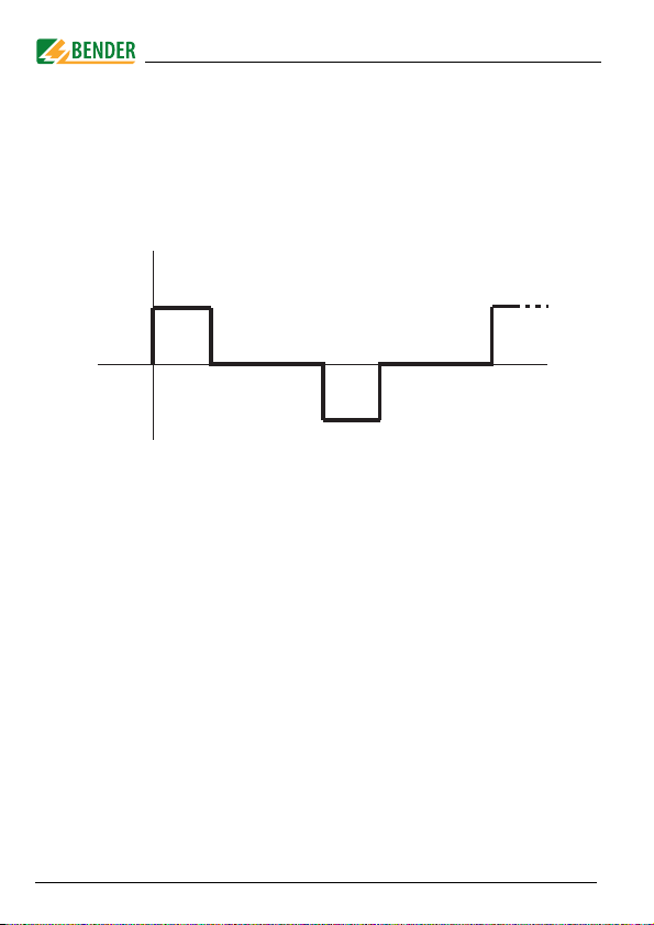
3.2.2 Test cycle
The duration of a test current pulse cycle is 6 seconds. The IRDH575 or
PGH... alternatively sends positive or negative test current pulses. The
test cycle of the IRDH575 or PGH... is shown in different switch posi-
tions (1,2,3) in the block diagram below, ("Block diagram EDS system"
on page 15).
EDS start
Position
PGH... 1331
sec 4 sec sec 4 sec

System description
17
TGH1394en/05.2007
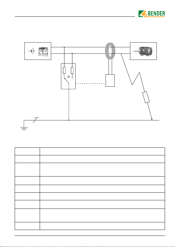
3.2.3 Currents in the EDS system
In addition to the block diagram on page 15, the path of the residual
currents and the test current is shown in the diagram below:
Key:
............. Test current loop I(ds)
.. .. .. .. Residual currents I(d) (example)
CE-V Upstream capacitances, system leakage capacitances
upstream the measuring current transformer.
CE-N Downstream capacitances, system leakage capacitances
downstream the measuring current transformer.
RF-V Insulation fault upstream the measuring current transformer.
RF-N Insulation fault downstream the measuring current trans-
former.
USV
IT-System
W...
EDS...
PE
RF-N
RF-V CE-N
CE-V
I(d), I(ds)
IRDH575/
PGH... 1
3

System description
18 TGH1394en/05.2007
The following residual currents flow through the measuring current
transformer of the EDS... :
the test current I(ds) caused by the insulation fault RF-N,
residual currents I(d) flowing through the system leakage capacitances
CE-V, CE-N, RF-V and RF-N,
transient leakage currents caused by switching and control activities in
the system,
low-frequency leakage currents caused by the use of converters.
3.2.4 Requirements for reliable insulation fault location
The EDS... is intended to detect insulation faults downstream of the
measuring current transformer RF-N. For this purpose, the test current
caused by the insulation fault has to be detected reliably, subject to the
condition that:
The test current I(ds) for the EDS460/490 is more than 2 mA and less
than 50 mA.
The test current I(ds) for the EDS461/491 is more than 0.2 mA and less
than 5 mA.
The upstream capacitances CE-V must be at least as large as the down-
stream capacitances CE-N.
The system leakage capacitance does not have to be too large (see
"Response sensitivity characteristics" on page 71).
The total residual current through the measuring current transformer
(test current and residual currents etc.) may be a maximum of 10 A
(EDS460/490) respectively 1 A (EDS461/491).
Not only does the amplitude influence the reliable detection of the test
current but also the residual current frequency. This effect is illustrated
in the following fault curve.

System description
19
TGH1394en/05.2007
Fault curve
Safe fault location is possible in the grey-shaded area.
If insulation fault location is not possible on a measuring channel, the
EDS issues the message "peak".
Symmetrical insulation faults downstream of the meas-
uring current transformer are not recognized under cer-
tain circumstances.
Low-frequency residual currents (caused by converters,
for example) may have the effect that insulation faults
cannot be found when their frequency is equal or nearly
equal the text cycle frequency of the IRDH575 respective-
ly. PGH... .

Other manuals for EDS460
1
This manual suits for next models
3
Table of contents
Other Bender Diagnostic Equipment manuals


