Xtool N9EV User manual

Shenzhen Xtooltech Intelligent Co., LTD
User Manual
N9EV Smart Diagnostic System
Version 1.3
Revise date 2023/09

I
Please read this user manual carefully before using the XT90 Smart Diagnostic System, referred to as the “Scan Tool”
throughout this document. When reading the manual, please pay attention to the words “Note” or “Caution”, and read them
carefully for appropriate operation.
OPERATION INSTRUCTIONS
For safe operation, please follow the instructions below:
⚫Keep the device away from heat or fumes when in use.
⚫If the vehicle battery contains acid, please keep your hands and skin or fire sources away from the battery during
testing.
⚫The exhaust gas of the vehicle contains harmful chemicals. Please ensure adequate ventilation.
⚫Do not touch the vehicle cooling system components or exhaust manifolds when the engine is running due to the high
temperatures reached.
⚫Make sure the car is securely parked, Neutral is selected or the selector is at the P or N position to prevent the vehicle
from moving when the engine starts.
⚫Make sure the (DLC) Diagnostic Link Connector is functioning properly before starting the test to avoid damage to the
Diagnostic Computer.
⚫Do not switch off the power or unplug the connectors during testing. Doing so may damage the ECU (Electronic
Control Unit) and/or the Diagnostic Computer.
CAUTIONS!
⚫Avoid shaking, dropping or dismantling the scan tool as it may damage the internal components.
⚫Use only your fingertips to touch the LCD screen. Hard or sharp objects may damage the scan tool.
⚫Do not use excessive force;
⚫Do not expose the screen to strong sunlight for a long period.
⚫Please keep the scan tool away from water and moisture.
⚫Store and use the scan tool only within the temperature ranges identified in the Technical Specifications section.
⚫Keep the unit away from strong magnetic fields.
AFTERSALES-SERVICES
XTOOL strives to provide best-in-class support!
E-Mail: [email protected]
Tel: +86 755 21670995 or +86 755 86267858 (China)
Official Website: www.xtooltech.com

i
CONTENT
OPERATION INSTRUCTIONS ............................................................................................................................ I
CAUTIONS!.......................................................................................................................................................... I
AFTERSALES-SERVICES .................................................................................................................................. I
CONTENT ............................................................................................................................................................ I
1. GENERAL INTRODUCTION..................................................................................................................... 3
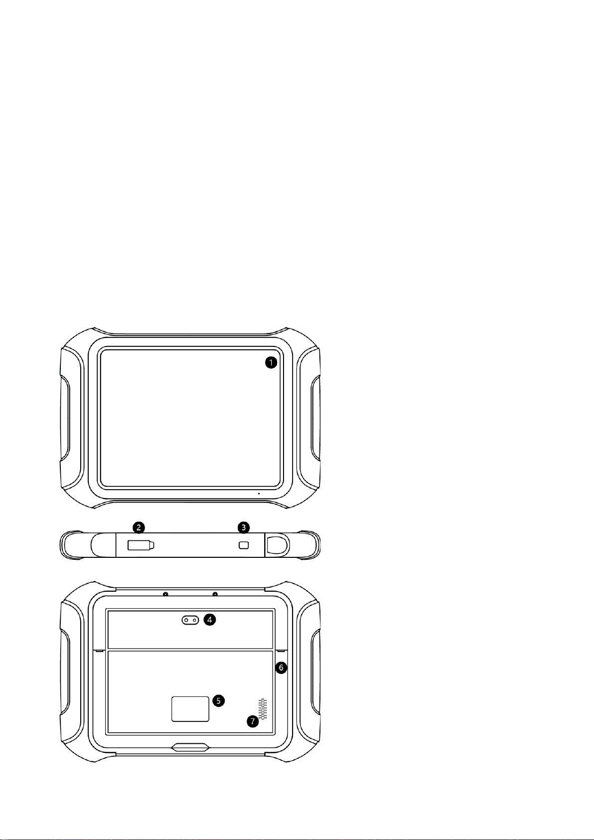
Main Units........................................................................................................................................................................3
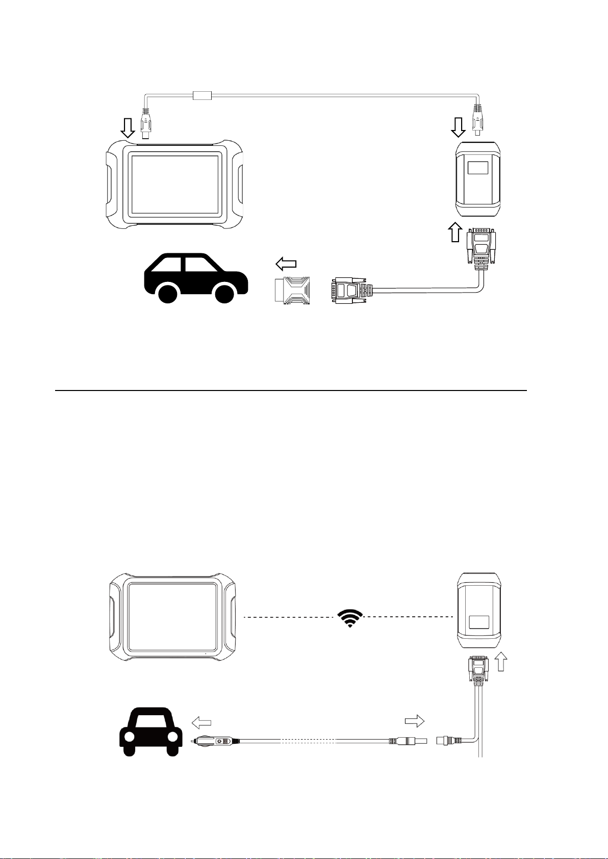
Vehicle Connection..........................................................................................................................................................5
WIFI connection ..................................................................................................................................................................................... 5
Wired Connection ................................................................................................................................................................................. 5
Self-test..................................................................................................................................................................................................... 6
2. DIAGNOSTIC ............................................................................................................................................ 7
Beginning Diagnostic Testing ..........................................................................................................................................8
Vehicle Selection.................................................................................................................................................................................... 8
Diagnosis functions............................................................................................................................................................................... 9
ECU Coding & Programming..........................................................................................................................................................16
3. BATTERY PACK DETECTION............................................................................................................... 18
4. CAN INSPECTION .................................................................................................................................. 18
5. COMPONENT TEST ............................................................................................................................... 20
Compressor detection....................................................................................................................................................20
OBC detection ...............................................................................................................................................................20
Component test-48V motor detection ............................................................................................................................21
DCDC detection.............................................................................................................................................................21
6. SPECIAL FUNCTIONS ........................................................................................................................... 21
ABS BLEEDING.............................................................................................................................................................21
OIL RESET....................................................................................................................................................................24

ii
EPB................................................................................................................................................................................25
SAS................................................................................................................................................................................27
BMS RESET..................................................................................................................................................................28
INJECTOR CODING......................................................................................................................................................29
DPF REGENERATION..................................................................................................................................................31
TPMS RESET................................................................................................................................................................34
7. REPORT.................................................................................................................................................. 37
Replay............................................................................................................................................................................39
File Manager..................................................................................................................................................................40
Data View ......................................................................................................................................................................40
8. UPDATE .................................................................................................................................................. 42
Update Software............................................................................................................................................................42
Delete Software ............................................................................................................................................................. 43
9. WARRANTY & SERVICES..................................................................................................................... 43
10. REMOTE ASSISTANCE ......................................................................................................................... 43

3
1. GENERAL INTRODUCTION
The XTOOL XT90 smart diagnostic system (referred to as the “Scan Tool”) is an advanced scanning tool based on the
Android operating system. It supports multiple languages and is suitable for different countries and regions. The advantage
of this OBD-II (On-Board Diagnostics version 2) scanner is its comprehensive functions and its ability to quickly provide the
user with more accurate diagnostic information.
XT90 Smart diagnostics System main units included:
•Tablet: P902
•Wireless Diagnostic Module: V207 VCI (Vehicle communication interface) box
•Other accessories
MAIN UNITS
⚫Tablet
1. 9.7-inch touch screen
2. Type-C Port
3. Power Button –Long press to turn
off/on the tablet, short press to enter
sleeping mode
4. Rear Camera
5. Nameplate
6. Holder
7. Speaker

4
⚫VCI Box
1. DB15 Port
2. Display with vehicle voltage
3. Type-B Port
⚫OBD2-16 Adapter
1. OBD Male Connector –Plug into vehicle’s
DLC port
2. DB15 port –Connect to main cable
⚫DB15 Main Cable
1. DB15 Port –to OBD2-16 Adapter
2. DB15 Port –to VCI
3. 12V DC Power Input Port

5
VEHICLE CONNECTION
WIFI CONNECTION
The WIFI connection method is shown in the figure below:
The scan tool must be connected to the vehicle’s OBD-II port so that the tablet can establish correct vehicle communication.
Please perform the following steps:
1 Turn on the tablet
2 Connect VCI with Vehicle via main test cable and OBD adapter, make sure WIFI connection works fine
3 Switch on the ignition and tap on the Diagnostic application to start your diagnosis.
WIRED CONNECTION
When using functions such as ECU programming & coding, please use the USB 3.0 to TYPE-B main cable to connect the
tablet to the VCI box to prevent the failure of function execution due to unstable data transmission and thus any other
damage.
Note: The vehicle’s DLC is not always located under the dash; for the location of the DLC, please refer to
the vehicle owner’s manual. Some older vehicles are not compatible with the OBD
Ⅱ
-16 adapter, please make
sure you’re using the correct adapter.

6
1. Type-C to Type-B cable
2. DB15 Main Test cable
3. OBDII-16 Adapter
For models with DoIP protocol communication, please be sure the device is connected to vehicle by wire.
SELF-TEST
The self-test is mainly used to detect whether there is a fault in the internal hardware of the device. When performing the
self-test function, please do not connect the VCI box or tablet directly to the vehicle’s OBD port, otherwise irreversible
damage may be caused to your vehicle!
•Plug the power cord into the 12V DC port of the VCI box
•Enter the following path: Main Menu>>Setting>>Self-test, make sure the device is not connected to any vehicle, click
OK to perform self-test function
①
②
③
①
④
②
③

7
1. Cigarette Lighter
2. DB15 Main test cable
3. VCI box
4. Tablet
⚫Precautions for Diagnosis
1. The voltage range on the car: +9~+36V DC;
2. When testing some special functions, the operator must operate according to the prompts and meet the test conditions.
For some models [special functions], the conditions that need to be met are: engine water temperature 80 ℃~105 ℃, turn
off headlights and air conditioners, keep the accelerator pedal in the released position, etc.;
3. The electronic control systems of different models are very complicated. If you encounter situations where it is impossible
to test or a large amount of test data is abnormal, you can search for the ECU of the vehicle and select the menu for the
model on the ECU nameplate;
4. If the vehicle type or electronic control system to be tested is not found in the diagnostic function, please upgrade the
vehicle diagnostic software to the latestversion using the Updates menu or consult the XTOOL technical service department;
5. Only wiring harnesses provided by XTOOL and designed for the scan tool are permitted to be used with this scan tool to
avoid damage to the vehicle or the scan tool;
6. When running a Diagnostics function, it is forbidden to shut down the scan tool directly. You should cancel the task before
returning to the main interface and then shutting down the scan tool.
2. DIAGNOSTIC
The N9EV supports two diagnostic modes, EV mode and normal diagnostic mode, both of which support diagnostics, but
there is a difference in the models covered by their diagnostic functions. EV mode supports diagnostics for pure electric
vehicles and hybrid models only. General diagnostic mode supports gasoline, diesel, hybrid and pure electric models. It
should be noted that some pure electric vehicles can only be used in EV mode, such as Tesla. In addition to diagnostic
functions, EV mode also features battery pack dynamic inspection and component testing.

8
The diagnostic application can read ECU information, read and clear DTC (Diagnostic Trouble Codes) and check live data
and freeze frame data. The Diagnostic application can access the ECU of various vehicle control systems, including the
Engine, Transmission, Anti-lock Braking System (ABS), Airbag Safety Restraing System (SRS), Electronic Parking Brake
system (EPB) and perform many types of actuation tests.
BEGINNING DIAGNOSTIC TESTING
After the tablet device is properly connected to the vehicle, you could start the vehicle diagnosis.
VEHICLE SELECTION
Click the “Diagnostic” icon on the main screen and get into the diagnostic menu. Like the immobilizer menu, the brands will
be shown on the screen. Select the region of your vehicle, click the correct brand, and start the diagnostic process.
For some of the vehicle brands (like Volkswagen), when you click on the software, there are several ways to select the
model or system you want to run a diagnostic, including Automatic Detection, Manual Selection, and System Selection.

9
Automatic Detection will automatically identify the vehicle's VIN code, and then read the information of your target diagnostic
object. If you choose "Manual selection", then you can continue to select the vehicle brand, year, and model of the vehicle
in the sub-menu to diagnostic the vehicle. Enter "System Selection", you can also diagnose the vehicle according to the
system according to your needs after selecting the model.
⚫OBDII menu supports reading the common fault codes in the engine. The DTCs may not be the same when compared
with using common diagnostic software.
⚫DEMO is a demonstration program. You can perform basic diagnostic functions without connecting to the car. .
DIAGNOSIS FUNCTIONS
Diagnostics functions supported by the scan tool are listed below:
⚫Read ECU Information
⚫Read/Clear Trouble Code
⚫Read Live Data
⚫Freeze Frame
⚫Actuation Test (Bi-Directional Control)
⚫Special functions
⚫READ ECU INFORMATION
This function is to read ECU version information and is the equivalent of "System Identification" or "System Information”
in some electroniccontrol systems. These equivalent termsall refer to reading ECU-related software andhardware versions,
models and production date of diesel engines, part numbers, etc. This information is helpful when recording maintenance
records and ordering new parts

10
⚫READ TROUBLE CODE
In the process of diagnosis, if the device shows “System is OK”or “No Trouble Code”, it means there is no related trouble
code stored in ECU or some troubles are not under the control of ECU. Most troubles are mechanical system troubles or
executive circuit troubles. It is also possible that the signal of a sensor may be inaccurate but within limits, which can be
examined using Live Data.
⚫CLEAR TROUBLE CODE
It allows for clearing current and historical trouble codes stored in the ECU memory, under the premise that all the troubles
have been resolved.
Some troubles are immediately detected by the ECU with the key in the run position and without the engine running. Other
troubles are not detected until very specific test conditions are met such as engine coolant temperature within a range,
speed within a range for a duration of time, throttle percentage within a range, etc.
If the trouble codes are erased when the trouble remains unresolved, the trouble code will reappear in the ECU the next
time the ECU performs the specific diagnostic test for that trouble.
If the trouble is resolved but there is a stored trouble code, sometimes the ECU will detect the resolution and clear the
trouble code or more likely, classify it as “historical” trouble.
If the trouble is resolved and the user clears the trouble codes, the trouble history will be cleared.
If the user intends to have another colleague or mechanic investigate the problem, it is not recommended for the user to
clear the trouble code since doing so may erase information helpful to others who may investigate the issue.

11
⚫READ LIVE DATA
Real-time information about various sensors is called “Live Data”. Live Data includes parameter identifications (PIDs) of
the running engine such as oil pressure, temperature, engine speed, fuel oil temperature, coolant temperature, intake air
temperature, etc. Based on these parameters, we can predict directly where the problem lies, which helps to narrow the
scope of maintenance. For some vehicles, during their actual operation, the problems such as performance characteristics
or sensitivity reduction, can be evaluated using live data.
!Note: The speed may vary depending on the speed of data sent from the vehicle and the number of data parameters being
shown.
Click the magnifying glass on the top right, you can search for related PIDs based on keywords

12
⚫Custom
The scan tool includes support to select and show multiple PIDs. Click Display All to display all PIDs. This enables you to
see relationships between data parameters.
⚫Graph
Click Graph to switch to multi-line graph mode. Click List to display all selected PIDs as a list

13
⚫Combine
The scan tool includes support to select multiple PIDs and click Combine to combine different graphs into one chart.
⚫Data recording
The scan tool supports recording the current data values in the form of text. You can view the recorded files in
Reports->Data Replay.
⚫Pause
Click this button to pause the recording timeline. It freezes the data display, for closer examination and review.

14
⚫FREEZE FRAME
When the signal of the sensor is abnormal, the ECU will save the data at that moment of failure to form a freeze-frame. It is
usually used to analyze the reasons that may lead to component(?) failures.
The live data items supported by vehicles of different brands are not the same, so the freeze frames displayed when
diagnosing vehicles of different brands may also be different. Some vehicles may not have the option of a freeze-frame
which means that the model does not support this function.
Take Renault Duster ii ph as an example. After selecting the system to enter the lower freeze frame menu, the device will
list all the fault codes under the system.
Users can click on a fault code, such as DF1068 to view the freeze frame recorded by the car when the fault code occurs,
including context when the fault appeared, and current context and additional data.

15
Context when fault appeared: record the live data when fault appeared to help the user to know the vehicle status. *Some
vehicles don't support this function; users will get a prompt when they click the menu.
Current context: Displays the current live data stream associated with the DTC
Additional data: record other data related to the fault
⚫ACTUATION TEST (BI-DIRECTIONAL CONTROL)
Actuation test, also known as bidirectional control, is a generic term used to describe sending and receiving information
between one device and another. This function is used mainly to judge whether these actuating components of the engine
are working properly.
The vehicle engineers responsible for designing computer control systems programmed them so a scan tool could request
information or command a module to perform specific tests and functions. Some manufacturers refer to bidirectional controls
as functional tests, actuator tests, inspection tests, system tests or the like. Reinitialization and reprogramming also can be
included in the list of bidirectional controls.
This function allows the device to send information to and receive information from, vehicle control modules. For example,
in the case of OBD II generic information Mode 1 (which relates to data parameters), the scan tool user initiates a request
for information from the powertrain control module (PCM), and the PCM responds by sending the information back to the
scan tool for display. Most enhanced scan tools also can actuate relays, injectors and coils, perform system tests, etc. Users
could check the individual part to see what is working properly by actuation test.

16
⚫SPECIAL FUNCTIONS
Usually, special functions provide various reset or re-learning functions menus for most vehicle systems. You can easily and
quickly solve some faults through special functions for your car. After some functions are successfully executed, fault codes
will be generated, which need to be cleared manually after the car is running for a little while which could include a single
start of the engine or multiple warm up cycles.
And under each system, you can view the special features supported by that system. Different models and systems often
have different special functions. Even for the same system of the same model, the years and ECU type may lead to different
special functions supported.
ECU CODING & PROGRAMMING
Since the introduction of OBD II and leading up to modern Hybrids and EVs, computers, and software in cars have been
expanding at an exponential rate. In-car software is becoming one of the leading needs for service, and updating software
may be the only way to fix some of these issues:
•Drivability
•Fuel Efficiency
•Power Loss
•Fault Codes
•Durability of Mechanical Parts

17
The Programming and Coding function is used to re-flash the vehicle control modules, which allows you to update the
computer software of the vehicle to the latest version, as well as to reprogram adaptive data of certain components after
making repairs or replacements.
There are two general types of programming operations:
⚫ECU Coding
ECU Coding, also known as Teach-in Program, or Component Adaptation, is used to reprogram adaptive data for electronic
control modules after repairs or replacements of parts.
*NOTE: Codable control modules/components are system-specific, which means that not all control modules are
codable.
⚫ECU Programming
ECU Online programming means a user could download the latest version of the software from the online server database
through Internet access (this procedure is done automatically when the tablet is connected to the Internet, so there is no
need to check for software updates yourself), and reprograms the newest version into the ECU of vehicles.
Reprogramming involves taking the following steps, but there may be changes related to the vehicle type, so please
complete the operation according to the actual situation and software prompts.
⚫Available programming or coding operations vary by test vehicle. Only the available operations are displayed in the
tablet menu.
⚫The programming function applies only when the vehicle is connected with a VCI device, which serves as a PassThru
interface to establish communication with and transfer data to the vehicle’s ECU.
⚫Before applying the ECU programming function, please make sure that the tablet computer is connected to a stable
Internet connection so that the tablet computer can access the vehicle manufacturer's server for update services.
⚫Selecting the programming or coding function will open a menu of operating options, which differs depending on the
vehicle’s make and model. Selecting a menu option either displays a programming interface or opens another menu
containing other options. When performing programming or coding operations, follow all instructions on the screen.
The way and content of the information displayed on the screen differ depending on the type of operation being
performed.
NOTE: For some vehicle brands, such as BMW, the ability to program a module is limited to the number of times it
has already been programmed and the hardware version of the control module itself.
⚫IMPORTANT
When reprogramming onboard, please always make sure the vehicle battery is fully charged and in good working condition
to avoid the operation failure caused by the abnormal voltage below the proper operating voltage. Sometimes the failure
can be recovered, but the failed reprogramming can also cause a fault in the control module. We recommend connecting
an external battery maintainer to the vehicle to ensure asteady voltage is maintained throughout programming. The required
voltage differs by the vehicle manufacturer. Consult vehicle manufacturer for correct voltage to be maintained.
Occasionally a flash update procedure may not complete properly. Common causes of flash errors include poor
cable connections between the tablet, VCI, and vehicle, the vehicle ignition being switched off before the flash
procedure is complete, or low vehicle battery voltage.
If the process quits, recheck all the cable connections to assure good communications and initialize the flash
procedure. The programming procedure will automatically repeat if the previous operation does not succeed.
Please use this feature with caution and it is not recommended for non-professionals.

18
3. BATTERY PACK DETECTION
This function supports the detection of different types of battery packs for the mostly EV models on the market. It can read
the individual cell's voltage and each single temperature probe data of the vehicle’s battery pack.
It also allows checking the total voltage and the voltage of each cell in the battery pack and marks them with different colors
according to their value and range. You can easily get the cell position of Max/Min Volt and Temp by this functions, it helps
you locate the fault faster.
Click Set as Reference to save the current data as the reference value range. if the value is out of the reference range,
then the color of that cell will turn red automatically.
4. CAN INSPECTION
If the model of your battery pack is not covered, you can use the CAN INSPECTION function to collect data. It can detect
the pin voltage and custom the pin configuration, and support to check the baud rate, can automatically identify the OBD
pin voltage, and can quickly identify the CAN bus.
⚫Select More to enter the CAN INSPECTION function
Table of contents
Other Xtool Diagnostic Equipment manuals