3
PEM533_D00013_00_Q_XXEN/08.2013
Quick start: PEM533
Commissioning of the device Start
Check proper connection
Observe the relevant standards and regulations that have to be ob-
served for installation and connection as well as the manual of the
respective device.
Before switching on
Before switching on think carefully about these questions:
1. Does the connected supply voltage US correspond to the
nameplates information?
2. Is the nominal system voltage of the measuring current
transformer not exceeded?
3. Does the measuring current transformer's maximum current
correspond to the nameplate information of the connected
device?
After switching on
After switching on, proceed as follows:
1. Connect the supply voltage.
2. Set the bus address/IP address.
3. Set the CT transformer ratio (for each channel).
4. Change the measuring current transformer's counting direc-
tion, if required.
5. Set the nominal voltage.
6. Select wye connection or delta connection.
Pressing the "ENERGY/OK" button enters the setup mode (> 3 s).
Pressing the "ENERGY/OK" again (> 3 s) returns to the display
mode.
A correct password must be entered before changes are allo-
wed. (factory setting: 0)
The following diagram will help you to familiarise yourself with the
menu:
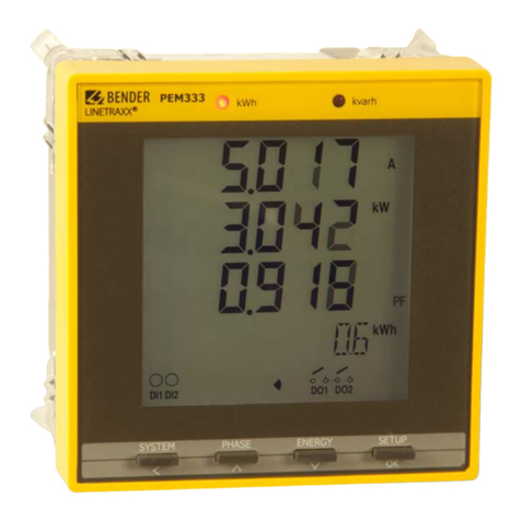
Display and operating controls
Key
LED "kWh" and LED "kvarh": pulse outputs
"V/I" button: displays mean values and total values
(current, voltage);
In the menu:
moves the cursor to the left if the parameter to be changed is
a numeric value
"POWER" button: displays energy-related parameters.
In the menu: to move up to the next entry;
in case of numeric values: increments the value.
"HARMONICS" button: displays harmonics.
In the menu: moves down to the next entry;
in case of numeric values: decrements the value
"ENERGY button:
Press > 3 s:
toggles between the setup menu and the standard mode.
Displays measuring values: Active and reactive energy import/
active and reactive energy export (line 5).
In the menu: selects the parameters for modification;
confirms parameter change.
Data display via buttons Data display via communication interface
All measuring values can be obtained from the device via the
buttons without having to use the communications interface.
Which button is to be activated to obtain the individual values is
described in more detail in the manual.
All measuring values can be obtained via the communications
interface. Details on the Modbus register assignment can be found
in the manual.
OK
OK
OK
OK
OK
OK
OK
OK
OK
OK
PROGRAMMING
Enter password PASWORD
Change password PAS SET
Set date DAT
Presetting
demands DMD SET
Presetting
energyvalues ENGY SET
Set time CLK
Trigger mode
digit. output DO SET
Info INFO
Device button
Systemsettings SYS SET
Clear memoryCLR SET
Communications
interface COM1 SET
Presetting
energypulsing PULS SET Activate energypulsing EN PULSE
Enter new password NEW PAS
Select connection type TYPE
Voltage transformer transf. ratio PT
Set baud rate BAUD
CT transformation ratio CT
Set pulse constant EN CONST
Clear energyvalues CLR ENGY
Clear max/min values CLR MXMN
Clear peak demand CLR PDMD
Reactive energyimport IMP kvarh
Active energyexport EXP kWh
Active energyimport IMP kWh
Reactive energyexport EXP kvarh
Apparent energyS kVAh
Serial number
Date update UPDAT
Protocol version PROVER
Software version SW-VER
Set address ID
Paritybit CONFIG
kVA calculation method KVA SET
Power factor rule PF SET
Sliding Windows NUM
Measuring period PERIOD
DO1 control DO1 Control
Change polarityI3I3 REV
Change polarityI2 I2 REV
Change polarityI1 I1 REV
DO2 control DO2 Control
Clear pulse counter CLR DIC
Clear event memoryCLR SOE
Duration of
displaylighting BLTO SET
>3 s
ENERGY/OK
kvarh
kWh
PEM575
LINETRAXX®
V/I POWER HARMONICS ENERGY
OK
