Function
16 isoPV1685-1685PFR_D00007_02_M_XXEN/10.2016
3.3 Description of function
Insulation monitoring is carried out using an active measuring pulse which is superimposed onto the
PV system to earth via the integrated coupling.
isoPV1685:
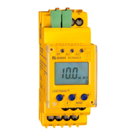
When the insulation resistance between the IT system and earth falls below the pre-set prewarning
response value Ran1, LED "Alarm 1" lights and the alarm relay K1 switches. When the value also falls
below response value Ran2, LED "Alarm 2" lights too and the alarm relay K2 switches.
isoPV1685P:
When the insulation resistance between the IT system and earth falls below the pre-set prewarning
response value Ran1, LED "Alarm 1" lights and the alarm relay K1 switches. When the value also falls
below response value Ran2, LED "Alarm 2" lights too and the alarm relay K2 switches.
The locating current injector integrated in the device for insulation fault location is externally acti-
vated via the BMS interface or, when no master is available, via the integrated substitute master
function. When starting insulation fault location, the LED "PGH on" signals the locating current
pulse.
The insulation fault location can be started in the manual mode via the digital input 1. E.g. for the
insulation fault location with mobile insulation fault locator (e.g. EDS195).
isoPV1685PFR:
When the insulation resistance between the PV system and earth falls below the set prewarning re-
sponse value Ran1, only LED "Alarm 1" lights. When the value also falls below the alarm response val-
ue Ran2, the alarm relay K1 switches and the LED "Alarm 2" lights.
The residual current is detected via an external measuring current transformer. The r.m.s. value is cal-
culated by summing up the AC component that are below the cut-off frequency. When the residual
current exceeds the set alarm response value, the corresponding alarm relay K2 switches and the as-
sociated LED "Alarm IdN" lights up.
All relevant measured values and their statuses (Normal, Prewarning, Alarm) are cyclically sent via
the CAN interface.
The locating current injector integrated in the device for insulation fault location is externally acti-
vated via the BMS interface. When starting insulation fault location, the LED "PGH on" signals the lo-
cating current pulse.
The integrated µSD card (isoPV1685PFR only) is used as data logger for storing all relevant events.
The following measured values, statuses and alarms are stored during operation:
– Insulation resistances and leakage capacitances
– Residual currents
– System voltages, partial voltages to earth, supply voltages
– Temperatures: current controller PGH, coupling L+, L–
– Insulation fault, residual current fault
– Connection fault
– Device error
Following each start-up, a new log file is generated. If the current file size exceeds 10 MByte during
operation, a new file is generated. The file name contains the time and date of the creation time. The
typical time that is needed until the maximum file size is reached is approximately 2 days. Hence, a
SD card with a memory space of 2 GByte can record data for approx. 400 days. When the maximum
data limit is reached on your card, the oldest file in each case will be overwritten.
The history memory that is also copied to the µSD card contains all alarms in csv. format.


