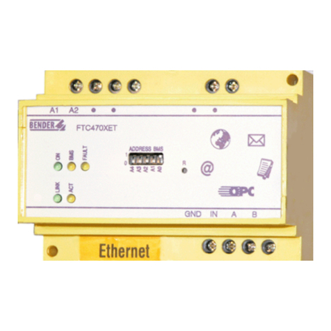
Bender FTC470XDP User manual

Manual
EN
Protocol converter for the connection
of the Bender Measuring interface
to the PROFIBUS DP
Software version: D143 V2.1x
FTC470XDP_D00111_00_M_XXEN/02.2015
FTC470XDP

Bender GmbH & Co. KG
P.O. Box 1161 • 35301 Gruenberg • Germany
Londorfer Straße 65 • 35305 Gruenberg • Germany
Tel.: +49 6401 807-0 • Fax: +49 6401 807-259
© Bender GmbH & Co. KG
All rights reserved.
Reprinting only with permission
of the publisher.
Subject to change!
Photos: Bender archives and bendersystembau archives.

3
Table of Contents
FTC470XDP_D00111_00_M_XXEN/02.2015
1. How to use this documentation effectively ....................................................... 7
1.1 About the operating manual ............................................................................................... 7
1.2 Overview of the individual chapters ................................................................................. 7
1.3 Brief instruction ........................................................................................................................ 8
2. Safety instructions .................................................................................................. 9
2.1 Work activities on electrical installations ........................................................................ 9
2.2 Address setting and termination ....................................................................................... 9
3. Standard application ........................................................................................... 11
3.1 Bus interface ........................................................................................................................... 11
3.2 Application of the FTC470XDP ......................................................................................... 12
3.3 Restrictions .............................................................................................................................. 12
4. The FTC470XDP protocol converter ................................................................. 13
4.1 Scope of delivery ................................................................................................................... 13
4.2 Display and operating elements ..................................................................................... 13
4.2.1 PROFIBUS DP status indicators ........................................................................................ 14
4.2.2 Status indicators for the BMS bus and supply voltage .......................................... 14
4.3 BMS side of the FTC470XDP .............................................................................................. 15
4.4 PROFIBUS DP side of the FTC470XDP ............................................................................ 16
4.4.1 Cyclical data exchange ....................................................................................................... 16
4.4.2 Correct time control of the FTC470XDP by PROFIBUS commands is
required .................................................................................................................................... 16
4.4.3 FTC470XDP communicates with the PROFIBUS DP Master as ’BMS Slave’ ...... 17
4.4.4 The FTC470XDP communicates as the ’BMS Master’ with the PROFIBUS DP
Master ........................................................................................................................................ 18
4.4.5 Format of output and input data .................................................................................... 19
4.5 Intended use ........................................................................................................................... 21
5. Installation ............................................................................................................. 23
5.1 Basic configuration ............................................................................................................... 23
5.2 Mounting and connection of the device ...................................................................... 24
5.2.1 Wiring diagram ...................................................................................................................... 25

Table of Contents
4FTC470XDP_D00111_00_M_XXEN/02.2015
6. Function ................................................................................................................. 27
6.1 GSD file for the PROFIBUS DP Master ............................................................................. 27
6.2 Function lists ........................................................................................................................... 27
6.3 Requesting alarm messages .............................................................................................. 28
6.3.1 Number of all alarm messages of a BMS device ......................................................... 28
6.3.2 Requesting alarm messages via the channel number ............................................. 29
6.4 Requesting operating messages ...................................................................................... 32
6.4.1 Number of all operating messages of a BMS device ................................................. 32
6.4.2 Requesting operating messages via the channel number ..................................... 33
6.5 Requesting measuring values ........................................................................................... 35
6.5.1 Requesting measuring values via the channel number .......................................... 35
6.6 Taking over or returning the Master function ............................................................. 36
6.6.1 Taking over the Master function ...................................................................................... 36
6.6.2 Returning the Master function ......................................................................................... 36
6.7 Parameterization .................................................................................................................... 37
6.7.1 Requesting the response values via channel number ............................................. 37
6.7.2 Setting the response values via channel number ..................................................... 39
6.7.3 Requesting the delay on response .................................................................................. 41
6.7.4 Setting the delay on response .......................................................................................... 41
6.7.5 Requesting the CT type ....................................................................................................... 42
6.7.6 Setting the CT type ............................................................................................................... 42
6.7.7 Requesting the status of CT monitoring ....................................................................... 43
6.7.8 Setting the status of CT monitoring ................................................................................ 43
6.7.9 Requesting the correction factor for the CT transformation ratio ....................... 44
6.7.10 Setting the correction factor for CT transformation ratio ....................................... 44
6.7.11 Requesting the fault memory ........................................................................................... 45
6.7.12 Setting the fault memory .................................................................................................... 45
6.7.13 Requesting the operating mode of the alarm relay .................................................. 46
6.7.14 Setting the operating mode of the alarm relay .......................................................... 46
6.7.15 Requesting the channel function .................................................................................... 47
6.7.16 Setting the channel function ............................................................................................. 47
6.7.17 Requesting the number of measurements per channel ......................................... 48
6.7.18 Setting the number of measurements per channel .................................................. 48
6.7.19 Requesting the maximum number of measurements ............................................. 49
6.7.20 Setting the maximum number of measurements ..................................................... 49
6.8 Requesting device-specific information ....................................................................... 50
6.8.1 Requesting fault messages after a self test .................................................................. 50
6.8.2 Requesting the software version ..................................................................................... 50
6.8.3 Requesting the device type and device version ........................................................ 51
6.9 Control commands for use in BMS Master mode ...................................................... 52

Table of Contents
5
FTC470XDP_D00111_00_M_XXEN/02.2015
6.9.1 Deleting all alarm messages ............................................................................................. 52
6.9.2 Starting a self test of insulation monitoring devices ............................................... 52
6.9.3 Starting the self test of an EDS system .......................................................................... 53
6.9.4 Buzzer mute ............................................................................................................................ 53
6.9.5 Switching the relay of a specific channel ..................................................................... 54
6.10 Control commands to be used in the BMS Slave mode ......................................... 55
6.10.1 Starting and stopping EDS systems ............................................................................... 55
6.11 Output of PROFIBUS messages via the BMS bus ....................................................... 56
6.11.1 Output of PROFIBUS alarm messages via BMS bus .................................................. 56
6.11.2 Output of PROFIBUS operating messages via BMS bus .......................................... 56
7. Programming examples ..................................................................................... 57
7.1 Alarm messages ..................................................................................................................... 57
7.1.1 Number of alarm messages .............................................................................................. 57
7.1.2 Requesting alarm messages or information via channel number ...................... 58
7.2 Operating messages ............................................................................................................ 60
7.2.1 Requesting the operating messages via channel number .................................... 60
7.3 Requesting the measuring values via channel number ......................................... 62
7.4 Temporary Master takeover and return ........................................................................ 64
7.4.1 Taking over the Master function ..................................................................................... 64
7.4.2 Returning the Master function ......................................................................................... 64
7.5 Control commands for use in the Master mode ........................................................ 65
7.5.1 Interrogating the FTC470XDP device type .................................................................. 67
7.6 Control commands for use in the BMS Slave mode ................................................. 68
7.6.1 Requesting the measuring value of all channels of an RCMS470-12 ................. 69
7.6.2 Requesting a device type after taking over the Master function by
FTC470XDP .............................................................................................................................. 70
7.6.3 Parameter setting after the FTC470XDP has taken over the Master function 71
8. Service and support ............................................................................................. 73
8.1 Damage in transit .................................................................................................................. 73
8.2 Malfunctions ........................................................................................................................... 73
8.2.1 What shall be checked? ...................................................................................................... 73
8.2.2 Where do you get help? .....................................................................................................73
8.3 Warranty claims ..................................................................................................................... 74
8.4 Warranty and liability .......................................................................................................... 74
9. Technical Data ...................................................................................................... 75
9.1 Technical data in tabular form ......................................................................................... 75
9.2 Dimension diagram .............................................................................................................. 76

Table of Contents
6FTC470XDP_D00111_00_M_XXEN/02.2015
9.3 Ordering details ...................................................................................................................... 76
9.4 Certification ............................................................................................................................. 76
INDEX ...........................................................................................................................77

7
FTC470XDP_D00111_00_M_XXEN/02.2015
1. How to use this documentation effectively
1.1 About the operating manual
This operating manual will concern qualified experts in electrical and communication
technology!
In order to make it easier to find certain text passages or references in this manual and for reasons of
comprehensibility, important information is emphasized by symbols. The meaning of these symbols
is explained below:
1.2 Overview of the individual chapters
How to use this documentation effectively:
This chapter provides information about the use of this documentation.
Safety instructions:
This chapter draws attention to hazards involved with the installation and operation.
Basic application:
This chapter deals with the normal use of this product.
The protocol converter FTC470XDP (gateway):
This chapter describes the scope of delivery, the operating and display elements available at
the device, the function of the protocol converter as well as the intended use.
Installation:
This chapter describes the device settings which are to be set prior to installation and the instal-
lation itself.
Function:
This chapter provides information about the device data file GSD includes a summary of all
PROFIBUS-DP commands that are transmitted to the FTC470XDP converter.
Programming examples:
This chapter contains various programming examples which are intended to help you
to configure the FTC470XDP.
Information calling attention to hazards is marked with this warning symbol.
Information intended to assist the user to make optimum use of the product is
marked with the Info symbol.

How to use this documentation effectively
8FTC470XDP_D00111_00_M_XXEN/02.2015
Service and support:
This chapter offers service and support in case of a fault. In addition you will find information
about the technical sales department.
Technical data:
This chapter provides an overview of technical data, a dimension diagram as well as the order-
ing details.
1.3 Brief instruction
If you are familiar with automation engineering, particularly with the PROFIBUS DP, it may be helpful
to start right away with chapter "4. The FTC470XDP protocol converter" and chapter "5. Installation".
In chapter 4 you will find information about the BMS-PROFIBUS DP communication model including
the ID numbers and start addresses required for read and write access. Chapter 5 provides informa-
tion about the basic configuration, installation as well as the connection of the FTC470XDP. Further-
more a wiring diagram is provided.

9
FTC470XDP_D00111_00_M_XXEN/02.2015
2. Safety instructions
2.1 Work activities on electrical installations
All work activities necessary for installation, commissioning or work activities during operation
of electrical devices or systems are to be carried out by adequately skilled personnel.
Observe the relevant regulations applying to work on electrical installations, in particular DIN
EN 50110 or its subsequent regulations.
If the equipment is used outside the Federal Republic of Germany, the respective national
standards and regulations are to be observed.
2.2 Address setting and termination
A prerequisite for proper functioning of the FTC470XDP protocol converter is its correct address set-
ting and termination.
Ensure correct address setting and termination of the FTC470XDP. For details refer to the chapter ba-
sic configuration on page 23.
Unprofessional work activities on electrical installations may result in
personal injury!
Addresses assigned twice may lead to serious malfunctions in BMS or
PROFIBUS-DP systems.

11
FTC470XDP_D00111_00_M_XXEN/02.2015
3. Standard application
3.1 Bus interface
In common building services management systems GLT as well as in other areas of automation en-
gineering a variety of field buses are used. Bender systems like EDS470/473, RCMS470 and MEDICS
communicate with each other via the Bender Measuring Interface BMS.
Our protocol converter FTC470XDP (gateway) is intended to connect this BMS interface to the
PROFIBUS DP. For that purpose, the FTC470XDP is connected to the PROFIBUS DP network in the
function of a PROFIBUS DP slave.
Fig. 3.1: Block diagram of an interface between the BMS bus and the PROFIBUS DP
120 W
A B A B A B
max. 1200 m
max. 1200 m
12345
ON
ON
0
5
1
2
3
4
6
7
8
9
0
5
1
2
3
4
6
7
8
9
BA
120 W
FTC470XDP
Bender Measuring device interface (BMS bus)
PROFIBUS-DP
PROFIBUS
slave
PROFIBUS master
PROFIBUS
slave
PROFIBUS
slave

Standard application
12 FTC470XDP_D00111_00_M_XXEN/02.2015
3.2 Application of the FTC470XDP
The connection of Bender systems to the BMS bus and to the PROFIBUS DP by means of the
FTC470XDP can become necessary for several reasons:
A PROFIBUS DP device is expected to respond to an event in the BMS world.
A BMS interface device is expected to respond to an event in the PROFIBUS DP world.
The BMS interface data and the PROFIBUS DP data are intended to be indicated and evaluated
centrally on a personal computer using PROFIBUS DP software.
The BMS interface data are to be indicated in the software of a building services management
system incorporating a PROFIBUS DP interface.
The configuration of devices of the BMS side is to be carried out via a personal computer with
PROFIBUS DP interface.
The control of certain BMS interface activities is to be carried out via the PROFIBUS DP.
3.3 Restrictions
Some Bender devices like TM operator panels or PRC1470 use in addition to the internal interface an
external interface capable of connecting such devices to extended networks. This external interface
cannot be addressed by the FTC470XDP. In BMS systems including TM operator panels or PRC1470
these components can only communicate with the FTC470XDP via the internal interface.
If FTC470XDP is operating to the internal interface of TM operator panel or PRC1470, a Master take
over cannot take place. In this cause only the functions described on page 17 can be used.
If the FTC470XET is operated on the internal bus of a PRC1470 or TM operator panel, the protocol
converter cannot take over the Master function. When operated in combination with these devices,
only Slave functions can be used. For details see “FTC470XDP communicates with the PROFIBUS DP
Master as ’BMS Slave’” on page 17.
Please note that some BMS Masters cannot return their Master function

13
FTC470XDP_D00111_00_M_XXEN/02.2015
4. The FTC470XDP protocol converter
This chapter describes:
the scope of delivery
the display and operating elements on the device
the function of the protocol converter
the intended use
4.1 Scope of delivery
Included are:
the FTC470XDP protocol converter
the technical manual
the configuration file ftc_1003.gsd
The latest version of this file is available on our Internet server. Load the file under:
http://www.bender-de.com => Download/Software
As soon as the Login procedure is completed, the category software will be displayed.
4.2 Display and operating elements
Fig. 4.1: FTC470XDP front plate
Figure Function
1 RS485 Socket for PROFIBUS cable: 9 pole Sub-D
2Micro switch for PROFIBUS DP termination:
"ON" = terminating resistor activated
3 Rotary switch for PROFIBUS DP address setting: 01-99
4 PROFIBUS DP status indication (further text below)
5 BMS bus status indication (further text below)
6 DIP-switch for BMS bus address setting: 1-30
12345
ON
ON
0
5
1
2
3
4
6
7
8
9
0
5
1
2
3
4
6
7
8
9
1234
56

The FTC470XDP protocol converter
14 FTC470XDP_D00111_00_M_XXEN/02.2015
Fig. 4.2: DIP-switch for the BMS bus address setting
4.2.1 PROFIBUS DP status indicators
4.2.2 Status indicators for the BMS bus and supply voltage
LED Meaning
RUN Green LED for the PROFIBUS DP, indicating that the FTC470XDP is con-
nected to the PROFIBUS DP. Data exchange is possible.
BF Red fault LED indicates that the FTC470XDP is not connected with a
PROFIBUS DP. Data exchange is not possible.
DIAG
Red diagnosis LEDs:
flash with a frequency of 1 Hz:
configuration faults. Input and output data of the FTC470XDP initializa-
tion are not in compliance with the configuration data.
Flash with a frequency of 2 Hz:
Fault in the user parameterization data. The length and the content of
the parameter data are not in compliance with the configuration data.
Flash with a frequency of 4 Hz:
fault during PROFIBUS DP ASIC initialization.
LED Meaning
ON Green Power On LED, lights in case of correct power supply
ALARM Yellow alarm LED lights when an alarm message is being transmitted to
the BMS side via the PROFIBUS DP.
FAULT
Yellow fault LED lights in case of disturbances on the BMS bus, e.g. when
an invalid BMS address has been set and/or in case of FTC470XDP mal-
functions.
BMS Yellow BMS LED indicates activities on the BMS bus.
A4 A3 A2 A1 A0
ADDRESS BMS
1
0

The FTC470XDP protocol converter
15
FTC470XDP_D00111_00_M_XXEN/02.2015
4.3 BMS side of the FTC470XDP
On the BMS side, the FTC470XDP can be used either as Master or as Slave.
BMS address 1 = Master mode
BMS address 2 = redundant Master mode
BMS address 2 to 30 = Slave mode
Data transfer rate = 9600 Baud
The following data is available on the BMS bus:
Alarm and operating messages
Bender devices with addresses 1-30 and 61-90 connected to the BMS bus cyclically send their alarm
and operating messages. Each device can send up to 12 alarm and operating messages. Each of the
channels 1-12 can be addressed separately.
Diagnostics and parameterization
This data is only be sent to the bus if requested by BMS commands.
Redundant Master function
FTC470XDP can be worked as a redundant Master. In the event failure of the regular Master (bus ad-
dress 1) the FTC470XDP takes over the Master function after approximately 60 seconds in order to
control the BMS bus. If the regular Master becomes active again, the "redundant" FTC470XDP returns
the Master function.
In case of failure of the regular Master tried first the BMS device with BMS address 2 to take over the
Master function. If the taking over does not succeed, address 3 etc. follows. That means, a
FTC470XDP with the BMS address 2 takes over the redundant Master function faster than equipment
with the address 30.
It is recommended to use the Master mode because of the fast data access.
The FTC470XDP provides the redundant Master function when the BMS address
2 to 30 was assigned to.

The FTC470XDP protocol converter
16 FTC470XDP_D00111_00_M_XXEN/02.2015
4.4 PROFIBUS DP side of the FTC470XDP
The FTC470XDP is a PROFIBUS DP slave in accordance with EN 50170. That means that at least one
Master must exist on the PROFIBUS side.
FTC470XDP = PROFIBUS DP slave
PROFIBUS DP address = 1…99
Data transmission rate = 9.6 kbit/s to 12 Mbit/s
Detection of the baud rate is carried out automatically.
4.4.1 Cyclical data exchange
In this manual, the PROFIBUS is generally regarded from the PROFIBUS DP Master’s point of view.
The communication process on the PROFIBUS DP is organized in cycles, which means that the PROFI-
BUS Master interrogates all PROFIBUS Slaves, one after the other. The Master sends a request to the
Slave, these represents the Master’s output data. In reply the FTC470XDP sends an answer, these are
the Master’s input data.
Due to the large amount of data on the BMS side, a cyclical data exchange is not possible at the same
time. For that reason, the PROFIBUS-DP Master must define the data he wants to receive from the
BMS device.
The allocation of input and output data is organized via a consecutive ID number. A request with the
ID number 1 must be followed by an answer from the Slave with the ID number 1. Only then the next
request with ID number 2 may be sent. Since one ID number needs 1 byte, the numbers from 0 to
255 can be allocated. Then it starts again with number 0.
4.4.2 Correct time control of the FTC470XDP by PROFIBUS commands is required
Since commands are intended for different devices, different time behaviour must be considered.
Answers to previously sent requests may accumulate while a PROFIBUS-DP Master’s request is being
answered by the associated Slave (FTC470XDP).Therefore it is of utmost importance to compare the
ID number of the request to the respective ID number of the answer.
Command typ.
duration
max.
duration BMS operation mode
Commands 1, 2, 3, 4, 102, 104, 105 execute 20 ms 100 ms Slave, Master
Switching commands execute 160 ms 600 ms Master, temporarily Master
Parameterizing 160 ms 600 ms Master, temporarily Master
Taking over the master function 6 s 60 s Slave
Returning the master function 100 ms 200 ms temporarily Master
The PROFIBUS programmer is responsible for the correct increment of the ID
numbers in compliance the system requirements. Wrong control of the time
behaviour may result in misinterpretations (PROFIBUS input data)!
Consider the duration for the execution of the instructions!

The FTC470XDP protocol converter
17
FTC470XDP_D00111_00_M_XXEN/02.2015
4.4.3 FTC470XDP communicates with the PROFIBUS DP Master as ’BMS Slave’
If a BMS address between 2 and 30 has been assigned to the FTC470XDP, it acts as a BMS Slave. In
this case, the PROFIBUS DP Master can use the following functions:
* For detailed information about the PROFIBUS instruction code refer to the tables "Function lists" on
page 27.
Temporary taking over of the Master function
Setting or requesting parameters of BMS cannot be carried out unless the FTC470XDP has taken over
the Master function on the BMS bus. After the setting respectively the requesting of parameters, the
Master function must be returned to the initial BMS Master. The associated commands can be found
on page 36.
If no parameters are transmitted to the BMS bus by the PROFIBUS DP for 200 seconds, the
FTC470XDP "assumes" that the Master function has not been returned. In this case, the FTC470XDP
automatically returns the Master function to the initial BMS Master in order to avoid that the BMS bus
is operated without a Master and hence would not be able to function reliably.
The response time for taking over or returning the Master function depends on the extension of the
BMS system. A typical response time is approximately 6 seconds, but may be up to 60 seconds in ex-
tended systems.
The time needed to execute the instruction codes 1, 2, 3, 4, 105, 102 and 104 is about 20 ms.
If FTC470XDP is operating to the internal interface of TM operator panel or PRC1470, a Master take
over cannot take place. In this cause only the functions described on page 17 can be used.
Function in the BMS network
PROFIBUS DP
instruction
code*
Request for the number of alarm messages of a device 1
Request for the alarm message of a channel 2
Request for the number of operating messages of a device 3
Request for the operating message of a channel 4
Request for the current measuring value of a channel 105
Transmission of an alarm message from the PROFIBUS to a chan-
nel of the FTC470XDP 102
Transmission of an operating message from the PROFIBUS to a
channel of the FTC470XDP 104
Starting, stopping or setting the position mode at EDS470/473
systems 115
Taking over respectively returning the Master function 112
Please note that some BMS Masters cannot return their Master function

The FTC470XDP protocol converter
18 FTC470XDP_D00111_00_M_XXEN/02.2015
4.4.4 The FTC470XDP communicates as the ’BMS Master’ with the PROFIBUS DP Master
Once the BMS address 1 is assigned to the FTC470XDP, the device acts as the BMS Master. In this way
it can act as Master in all BMS systems. In addition to the interrogation of alarm and operating mes-
sages, it is also possible to set switching commands and parameters.
The response time for the instruction codes 1, 2, 3, 4, 105, 102 and 104 is about 20ms as it is in the
slave mode. Switching commands and requesting of parameters are usually executed within ap-
proximately 160ms. Depending on the size of the BMS systems, however, also up to 600ms are pos-
sible.

The FTC470XDP protocol converter
19
FTC470XDP_D00111_00_M_XXEN/02.2015
4.4.5 Format of output and input data
The communication process is regarded from the PROFIBUS DP’s point of view. The PROFIBUS DP
Master sends the output data, a byte sequence, to the FTC470XDP (the PROFIBUS Slave). As an an-
swer, the input data is returned as a byte sequence to the PROFIBUS DP Master. As already explained
before, the assignment of input bytes and output bytes, i.e. of requests and answers, is carried out
via an ID number. The PROFIBUS DP programmer is responsible for the correct assignment of the
next ID number immediately after receiving an answer to the last request.
Format of output data:
Byte 1:
Consecutive ID No. of transmission. Must be set by the programmer of the PROFIBUS DP Master.
The ID number for the next request must be incremented as soon as an answer to the previous
request is received.
Byte 2:
No function, always zero (0) must be entered here
Byte 3:
BMS address of the addressed device. Note: TM operator panels and PRC1470 must be
addressed via their internal interface. Data of the external interface of these devices cannot be
processed by the FTC470XDP.
Byte 4:
BMS channel number of the addressed device. If no channel number is required, enter "0".
Byte 5:
BMS command code, refer to the tables on page 28. If no command code is required, enter "0".
Byte 6:
BMS data type, refer to the tables on page 28. If no data type is required, enter "0".
Byte 7:
BMS high byte data value, refer to the tables on page 28. If no data value is required, enter "0".
Byte 8:
BMS low byte data value, refer to the tables on page 28. If no data value is required, enter "0".
Byte 1 Byte 2 Byte 3 Byte 4 Byte 5 Byte 6 Byte 7 Byte 8
Consecutive
ID number of
transmission
always
"0"
BMS address of
the addressed
device
Channelnumber
of the addressed
device
Com-
mand
Type of data
value
High byte
data value
Low byte
data value

The FTC470XDP protocol converter
20 FTC470XDP_D00111_00_M_XXEN/02.2015
Format of input data:
Byte 1:
Consecutive ID No. of transmission. The ID number corresponds to the associated request (out-
put data).
Byte 2:
No function, the device reads always zero (0) here.
Byte 3:
BMS address of the addressed device. Address corresponds to the associated request (output
data).
Byte 4:
BMS channel number of the addressed device. Channel number corresponds to the associated
request (output data).
Byte 5:
BMS command code, refer to the tables on page 28. Command code corresponds to the associ-
ated request (output data).
Byte 6:
BMS data type, refer to the tables on page 28. The data type represents the requested result
read out by the device.
Byte 7:
BMS high byte data value, refer to the tables on page 28. The data value represents the
requested result read out by the device.
Byte 8:
BMS low byte data value, refer to the tables on page 28. The data value represents the
requested result read out by the device.
Byte 1 Byte 2 Byte 3 Byte 4 Byte 5 Byte 6 Byte 7 Byte 8
Consecutive
ID number of
transmission
always
"0"
BMS address of
the addressed
device
Channelnumber
of the addressed
device
Com-
mand
Type of data
value
High byte
data value
Low byte
data value
Table of contents
Other Bender Media Converter manuals


