NSR Marine NGT-200 User manual

USERMANUAL
NSR GMDSS TESTER
NGT-200
Test for MF/HF/VHF DSC & AIS/EPIRB/NAVTEX
NGT-200 UM.E 20210520-02

NGT-200 UM.E 20210520-02
MODIFY RECORD
No.
Modify by
Date
Paragraph
Version
Reason
1
Q/A
2019/12/12
01
First edition
2
Q/A
2021/05/20
all
02
Software upgrade

NGT-200 UM.E 20210520-02
CONTENTS
1 PURPOSE .................................................................................................................... 1
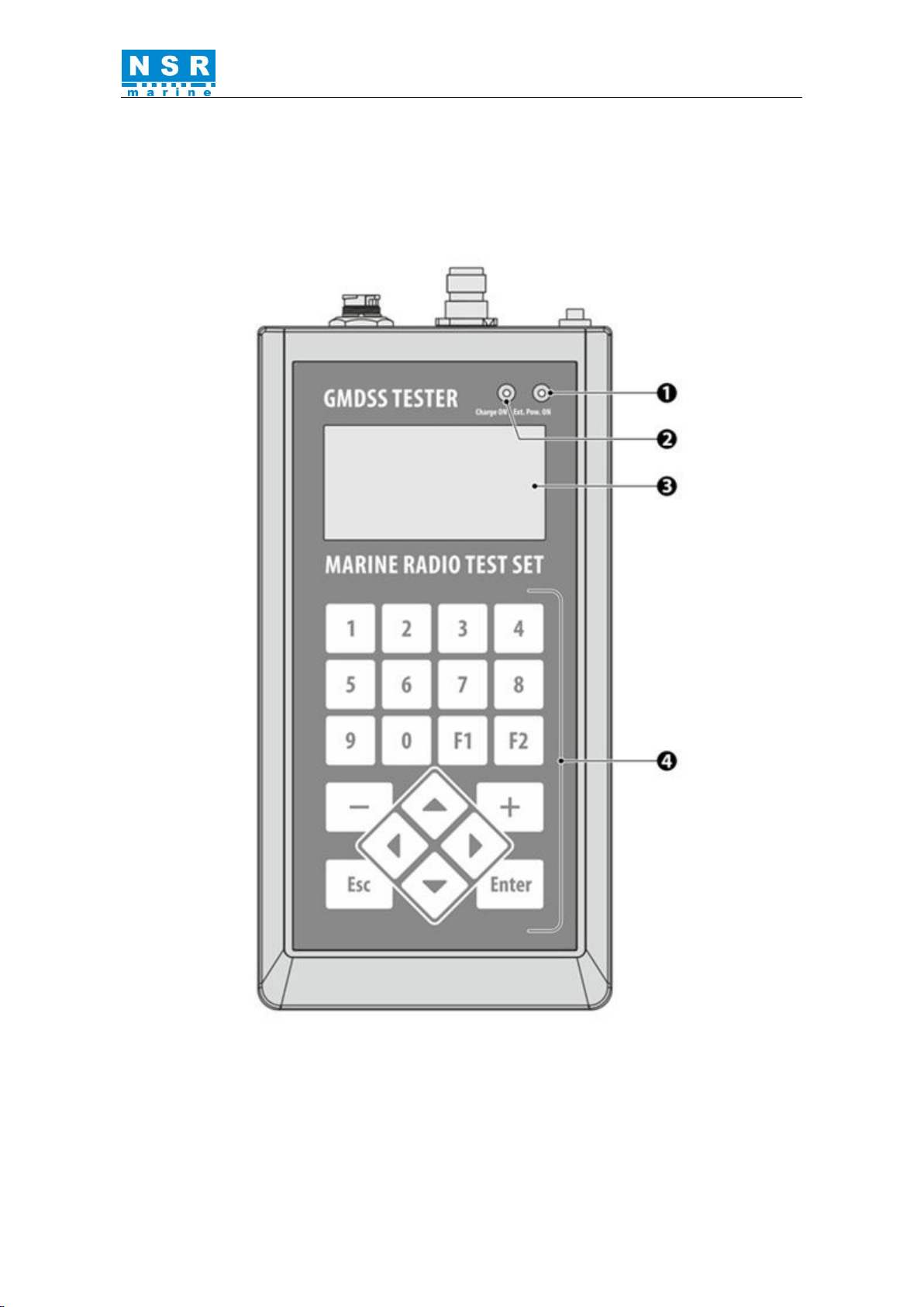
2 GENERAL VIEWS..................................................................................................... 3
2.1 Front view.............................................................................................................. 3
2.2 Top and Bottom views .......................................................................................... 4
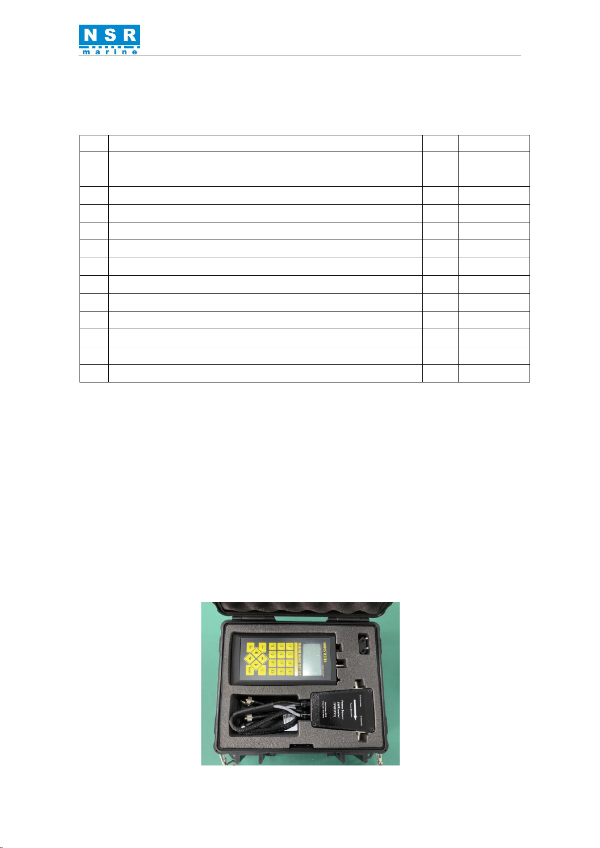
3 COMPLETE SET AND ACCESSORIES................................................................. 5
4 MENU TREE............................................................................................................... 6
5 RADIO TESTS............................................................................................................ 8
5.1 TEST VHF. Set of VHF Tests............................................................................ 8
5.2 TEST MF / HF –collection of MF / HF Tests ................................................. 15
5.3 TEST AIS –collection of AIS Stations and AIS-SARTs Tests ....................... 22
5.4 TEST EPIRB –EPIRB Testing Sets................................................................. 41
5.5 TEST NAVTEX –collection of NAVTEX Tests............................................. 46
5.6 TEST NMEA –collection of NMEA Interface Tests....................................... 48
6 TEST RESULTS........................................................................................................ 50
7 SETTINGS................................................................................................................. 54
7.1 SETTINGS > EDIT MMSI.............................................................................. 54
7.2 SETTINGS > SHIP ID ................................................................................... 55
7.3 SETTINGS > Test config ............................................................................... 56
7.4 SETTINGS > LCD contrast............................................................................. 57
7.5 SETTINGS > Setup date/time ........................................................................ 58
7.6 SETTINGS > Clear profiles ........................................................................... 58
7.7 SETTINGS > General info ............................................................................. 58
7.8 SETTINGS > U battery .................................................................................. 59
7.9 SETTINGS > Self test .................................................................................... 59
8 TECHNICAL SPECIFICATIONS.......................................................................... 60
9 RECOMMENDED TESTING PROCEDURES..................................................... 61
9.1 Typical setup of equipment connection for testing........................................... 61
9.2 Table of configurations and modes................................................................... 66
9.3 Step-by-step plan of checking of VHF radio station with DSC........................ 67
9.4 Step-by-step plan of checking the duplex VHF radio station........................... 68
9.5. Measurement of AIS station or AIS-SART parameters ................................... 69
10 TESTER’S CALIBRATION .................................................................................... 73
11 ENVIRONMENTAL AND MAINTENANCE GUIDELINE ............................... 74
12 POWER SUPPLY ..................................................................................................... 75
Appendix 1 UNIT CONVERSION............................................................................. 76
Appendix 2 SIGNALS PLACING ON RS232/RS422 IN/OUT OUTLET......... 77

NGT-200 USER MANUAL
NGT-200 UM.E 20210520-02
1
1 PURPOSE
NGT-200 NSR GMDSS Tester (Marine Radio Test Set) is intended to carry out the
operation, maintenance and servicing tests of MF/HF/VHF Radios with DSC and
NAVTEX receivers in accordance with IMO A.948 (23) or A.997(25), A.1020(26)
resolutions. Besides, if in extended version (A) Tester also lets to check AIS mobile
stations and AIS-SARTs according to the circular letter MSC.1/Circ.1252 and Cospas-
Sarsat beacons such as EPIRB, PLB, ELT, MOB devices in accordance with
MSC/Circ.1040.
NGT-200 supports testing of the following equipment:
●VHF transceivers:
- operation tests on any simplex channel including 6, 9, 13 and 16 channels;
- measurement of carrier frequency and frequency deviation;
- measurement of antenna feeder SWR, forward and reflected power;
●VHF transceivers with DSC:
- test of correct transmission/reception of DSC messages by means of
transmission/reception of distress or test call to particular MMSI number and
Distress (to all ships) messages;
- check the MMSI code programmed in equipment without any broadcast
emission;
- measurement of frequency and frequency deviation;
- measurement of output and reflected power;
●MF/HF radiotelephone equipment:
- measurement of frequency in range (1600 –30000) kHz;
- measurement of output power;
- functional tests in frequency range (1600 –30000) kHz;
●MF/HF controllers with DSC:
- check the MMSI code programmed in equipment;
- check receipt of DISTRESS signal by MF/HF equipment with DSC by means
of transmit of selective DISTRESS message;
●MF/HF radiotelephone equipment with DSC:
- test of correct transmission/reception of DSC messages by means of
transmission/reception of selective Test call to particular MMSI number and
Distress (to all ships) messages on any of 6 distress channels;
●NAVTEX equipment:
- operation tests by means of sending test message;
●VHF equipment of duplex radiotelephony (portable):

NGT-200 USER MANUAL
NGT-200 UM.E 20210520-02
2
- operation tests on channels 6, 9, 13, 16 (at least);
- measurement of output power, carrier frequency and frequency deviation;
●VHF equipment of duplex radiotelephony with airplanes including operating on
121.5MHz and 123,1MHz:
- operation tests by transmission/reception of modulated signal;
- measurements of frequency, output power level and frequency modulation
depth;
●VHF radiotelephone stations operating in range (300 - 337) MHz (intended for
river-sea vessels):
- measurement of output power, carrier frequency and frequency deviation;
●AIS mobile stations Class A and Class B and AIS-SARTs working in the Marine-
VHF band:
- measurement of output power, carrier frequency and antenna VSWR;
- receiving and decoding of the AIS messages;
- sending data/messages to AIS stations;
- passing the DSC polling information (channel 70);
- checking AIS response to “virtual vessels”.
●Cospas-Sarsat radio beacons:
- measurement of output power and carrier frequency on channel 406MHz;
- receipt, demodulation and decoding of messages on channel 406MHz;
- measure of output power level and carrier frequency on channel 121.5MHz;
- measure of output power level and carrier frequency on channel 243MHz;
NGT-200 allows to:
- generate the RF signals in range of 0.4 –30 MHz and 118 –275 MHz,
including those with tonal amplitude and frequency modulation;
- measure the signal frequency and power level of narrow-band radio signals in
range of 0.4 –30 MHz, 118 –137.5 MHz and 156 –163 MHz.
The tester is capable to transmit and receive the signals by:
-broadcast antenna
-direct connection to radiofrequency IN/OUT
-through Power sensor SWR meter
-direct connection by means of attenuator and cables (conductive measurements)

NGT-200 USER MANUAL
NGT-200 UM.E 20210520-02
3
2 GENERAL VIEWS
2.1 Front view
The front view of tester is shown on figure 2.1.
Fig. 2.1 NGT-200 front view

NGT-200 USER MANUAL
NGT-200 UM.E 20210520-02
4
2.2 Top and Bottom views
Fig. 2.2 NGT-200 top and bottom views
1 –green led: indication of external voltage supply;
2 –red led: indication of accumulator charging; after the accumulator is charged,
the led will fade;
3 –LCD;
4 –keyboard;
5 –USB-B socket for connection to PC and battery charging;
6 –audio output for connection 3,5 mm jack; Impedance > 8 Ω; right and left
channels are shorted;
7 –DB-9 socket for connection to RS232 / RS422 / RS485 interfaces;
8 –ON/OFF rocker switch;
9 –RF IN/OUT TNC connector;
10 –AUX: universal socket for VHF Power sensor VSWR meter connection.

NGT-200 USER MANUAL
NGT-200 UM.E 20210520-02
5
3 COMPLETE SET AND ACCESSORIES
The complete set of tester includes the items in accordance with table:
No
Item name
Qty
Notes
1
GMDSS Tester.
Marine Radio Test Set model NGT-200 main unit
1
2
Power adaptor
1
3
Telescopic antenna
1
4
NMEA cable IN/OUT (DB9 open wire)
1
5
USB-A –USB-B cable
1
6
VHF Power sensor VSWR meter (VHFPS1)
1
7
RF cable UHF male-UHF male RG58 1m
1
8
RF cable UHF female-UHF male RG58 0.5m
1
9
MF/HF Attenuator 40dB, 200W
1
Optional
10
Crushproof and watertight plastic box
1
11
Calibration Certificate
1
12
User Manual
1
VHF Power sensor VSWR meter (60W) - designed for conducted measurements
of the power and SWR in VHF frequency ranges; frequency range: 30 –410 MHz;
inserted attenuation between RF-In and NGT-200-Output: 63 dB.
* conducted measurements –measurements done by direct connection of equipment, e.g. by
means of RF-cable.
MF/HF Attenuator 40dB, 200W (optional) - used for conducted measurements
of the power in MF/HF frequency ranges.
NMEA IN/OUT cable - enables checking the Pilot plug performance capability
and checking of vessel’s transducers: GNSS, gyrocompass, log, etc.
Fig. 3.1 What inside the box

NGT-200 USER MANUAL
NGT-200 UM.E 20210520-02
6
4 MENU TREE
Fig. 4.1 NGT-200 main menu
The tester has user-friendly interface.
The tester operation is managed through MENU and 20 independent navigation
keys: numeric keys from 0 to 9 , menu navigation buttons ▲,▼, ◄, ►, Enter,
Esc , + , –, F1 and F2.
You can toggle between the menu lines using ▲and ▼keys.
Confirm/select something by means of Enter and Esc keys, cancel or move up
menu level by means of Esc key.
After the tester is turned ON it displays the device’s model, its serial number, date,
time and manufacturer logo.
Press Enter key to enter the main menu.
The main menu allows to select one of the operating modes, please see menu tree
on figure 4.1.
Each menu item has its own subsections. User moves among the subsections using
the same buttons as for the moving in main menu.
Use the Esc key to go back to main menu.

NGT-200 USER MANUAL
NGT-200 UM.E 20210520-02
7
Fig. 4.2Menu tree

NGT-200 USER MANUAL
NGT-200 UM.E 20210520-02
8
5 RADIO TESTS
5.1 TEST VHF. Set of VHF Tests
TEST VHF menu contains the following
items:
Send DSC –to send Test or Distress DSC
message;
Receive DSC –to receive DSC
message;
VHF Synthesizer –CW/SSB/AM/FM
RF signal generator;
VHF Receiver FM –narrow-band
signals measurement;
VHF Receiver AM –AM signals
measurement;
VHF Receiver ATIS –ATIS signals
measurement.
5.1.1 TEST VHF > SEND DSC
Select required message and press
Enter :
You can select between Test, Safety, and
Distress messages.
Test –special test message according
ITU-R M.493; it has format specifier –
120 (Individual call). So this message
will not disturb anybody except for DUT
(Device Under Test).
Safety - format specifier –120
(Individual call), category –108 (Safety).
Distress - DSC message with format
specifier –112 (DISTRESS). This
message can be accepted by any maritime
and coastal radio stations. Thus it is
recommended to send this DSC message
only by means of cable with reduced
level taking into account all safety
measures to avoid false DISTRESS
alert.
=== VHF: Send DSC ===
Select message:
Test
Safety
Distress
==== TEST VHF ====
Send DSC
Receive DSC
VHF synthesizer
VHF Receiver FM
VHF Receiver AM
VHF RECEIVER ATIS
Test config –F2

NGT-200 USER MANUAL
NGT-200 UM.E 20210520-02
9
Test message –if you select “Test”;
To : 413999333 –enter the correct
MMSI code of the DUT (Device Under
Test).
From: 413999997 –MMSI code of the
NGT-200 by default.
Pow : -40 dBm –power of the output
signal can be tuned with help of + , –
buttons with step 10dB; recommended
power level is -50 dBm to -20 dBm.
X–signalizes the selected measurement
configuration (same as below):
D- direct connection
¥- antenna
S- Power Sensor and VSWR meter
A- external attenuator
Measurement configuration can be
selected in menu SETTINGS / Test
config.
Press Enter to transmit Test message:
Repeated pressing of Enter will transmit DSC messages again. If necessary, output
power level can be adjusted.
To go back to menu SEND DSC, press Esc . Press Esc twice to enter MAIN
MENU.
ATTENTION: It is necessary to enter the correct MMSI number of tested radio
station to provide the reception of the TEST (Individual call) DSC message.
Otherwise the message will be sent but not be received by this station!
== VHF:Send DSC ==
Test message
To: 413999333
From: 413999997
Pow:-40 dBm X
--- Sending ---
== VHF:Send DSC ==
Test message
To: 413999333
From: 413999997
Pow:-40 dBm X
OK !
Repeat: press ENT
== VHF:Send DSC ==
Test message
To: 413999333
From: 413999997
Pow:-40 dBm X
Send –press Enter

NGT-200 USER MANUAL
NGT-200 UM.E 20210520-02
10
5.1.2 TEST VHF > RECEIVE DSC
After reception of the message
following information will appear
on the screen:
By entering this menu Tester is ready to
receive Test or Distress DSC message on
channel 70 with frequency 156525 kHz.
Tester is capable to receive DSC message
of category Individual call addressed to the
radio station specified by MMSI code.
Att: 20 dB –set the internal attenuation
level in range 0…93 dB.
Attenuation will be taken into account
during estimation of the received signal
level.
X–signalizes the selected measurement
configuration.
FIRST SCREEN of measurements:
MMSI: 413000000 –sender’s MMSI
code;
Format: Individual –format specifier:
Individual call (120);
Categ: Safety –category Safety (108);
CRC : OK –control sum;
To : 413999997 –receiver’s MMSI
code;
Save –F2 Prof:x ↓↑
- to save received information to memory
in selected profile press F2; profile number
is set up automatically;
- to receive messages again press Enter;
- to navigate the screens use buttons ▼,
▲.
= VHF:ReceiveDSC =
Wait for signal
Att: 20 dB X
= VHF:ReceiveDSC =
MMSI: 413000000
Format: Individual
Categ: Safety
CRC : OK
To : 413999997.
..................
Save –F2 Prof:x ↓↑

NGT-200 USER MANUAL
NGT-200 UM.E 20210520-02
11
SECOND SCREEN of measurements:
Freq: measured carrier frequency;
dev+: positive deviation of audio
subcarrier frequency 1700 Hz;
dev-: negative deviation of audio
subcarrier frequency 1700 Hz;
∆p-p :peak-to-peak deviation of
subcarrier frequency;
Pow.: measured power level of received
signal;
Saved OK ! - if you press F2 and save
data to memory.
5.1.3 TEST VHF > VHF SYNTHESIZER
The main task of this mode is testing of VHF-FM and VHF-AM radio stations
mobile and stationary; besides the Tester can operate as a RF signal generator.
CH: Number of the VHF channel (ITU);
F : Carrier frequency, kHz;
dF: Frequency tuning step;
L: Level of the output signal, dBm;
dL: Level step by keys + and - ;
Mod: FM - Modulation type;
Supported: FM>CW>SSB>AM>AMsweep;
F: 1.0k D:4.5kHz frequency
modulation and deviation on FM;
AMsweep –amplitude modulation of sweep
audio signals, it is applied in homing signal
(121MHz) of emergency beacons such as
EPIRB, ELT.
Frequency can be adjusted by one of the following ways:
1. By channel: You may directly input channel number or select it using
buttons + and –; all ITU simplex channels are available.
=VHF Synthesizer =
CH: 16
F: 156800 kHz
dF: 0025 kHz
L: -063 dBm X
dL: 10 dB
Mod: FM
F: 1.0k D:4.5kHz
= VHF:ReceiveDSC =
Freq:156525123 Hz
dev+: 400 Hz
dev-: -400 Hz
∆p-p: 800 Hz
Pow.: 44.3 dBm X
Saved OK !

NGT-200 USER MANUAL
NGT-200 UM.E 20210520-02
12
2. By frequency: You may directly input frequency using numeric buttons. If
the selected frequency corresponds to any of channels –the channel is
settled automatically. If the frequency doesn’t correspond to any of existing
channels, then channel will be shown (CH: --- ).
3. Frequency is tuned with a step (dF) with help of buttons + and –. The
step (dF) is tuned by selecting the position by buttons ◄and ►, tune it by
buttons + , –.
Frequency subranges:
a) 118 –275 MHz full range; for frequencies higher than 163MHz
accuracy of output signal is not guaranteed;
b) 118 –138 MHz avionic band, AM;
c) 156 –165 MHz marine band, FM-narrow;
d) 144 –146 MHz ham band, “2 meters”.
Output power level tuning:
1. Direct input of required level in dBm; due to the maximum level is 0dBm,
the input level is always understood as negative number.
For example, to settle (-45) dBm just press 4 and 5 . Minimal output level
is (-93) dBm or (+14) dBuV or 5 uV.
2. Output power level can be adjusted with step (dL) by means of + and –,
step can be set by direct input or increased/decreased by 10dB by means of
+ and –.
5.1.4 TEST VHF > VHF Receiver FM
The main purpose of this mode is measuring of power level, frequency and
frequency deviation of FM VHF stations. Also it can be used as regular nFM
receiver (nFM –narrow-band FM). Tester provides emission measurements
through broadcast by means of antenna and conductive measurements provided by
means of VHF Power sensor SWR meter (VHF PS1). You need to choose correct
measurement configuration in Test config. Menu, see Item 7.3 for details.

NGT-200 USER MANUAL
NGT-200 UM.E 20210520-02
13
Measurements through antenna:
CH : Operation channel (ITU);
F : Operation frequency, kHz;
dF : Frequency step;
Fx : Measured carrier frequency;
RSSI: Measured signal level;
¥ : test configuration –through antenna;
Fdev: peak carrier frequency deviation;
If the signal level is lower than (-90) dBm the
frequency and frequency deviation data will not be
displayed, the notification “Low level” is shown.
Press Esc to stop the measurements.
Measurement through VHF Pow. Sensor
SWR meter:
CH16 156800 kHz : by entering menu
you need to set up operating frequency;
To set up operating channel use numeric
keys;
Navigate using buttons ◄and ►, not while
measuring.
P: 43.5/11.3dBm S –incident /
reflected power.
S: measurement through Sensor (VHF
Power Sensor VSWR meter).
VSWR: 1.08 –measured VSWR.
Audio control:
Audio –F1: to turn ON audio control
mode of selected channel press F1.
Demodulated signal will be sent to audio-
output (position 6, Fig.2.2).
Frequency can be adjusted by one of the following ways:
1. By channel: You may directly input channel number or select it using buttons +
and –; all ITU simplex channels are available.
== FM Receiver ===
CH: 16
F: 156800 kHz
dF: 25 kHz
Fx: 156301567 Hz
RSSI: 44.1 dBm ¥
Fdev: 4.9 kHz peak
New-Enter Save-F2
Stop - Esc
= VHF-FM Receiver=
CH16 156800 kHz
dF : 25 kHz
Fx : 156301567 Hz
Fdev: 1234 Hz
P : 43.5/11.3dBm S
VSWR: 1,08
New-Enter Save-F2
Start - ENTER
= VHF-FM Receiver=
CH: 16
F: 156800 kHz
dF : 25 kHz
Audio –F1
Start –Enter

NGT-200 USER MANUAL
NGT-200 UM.E 20210520-02
14
2. By frequency: You may directly input frequency using numeric buttons. If the
selected frequency corresponds to any of channels –the channel is settled
automatically. If the frequency doesn’t correspond to any of existing channels,
then channel will be shown (CH: --- ).
3. Frequency is tuned with a step (dF) with help of buttons + and –. The step
(dF) is tuned by selecting the position by buttons ◄and ►, tune it by buttons
+ , –.
Measurements results can be saved in non-volatile memory of the Tester:
1. Stop measurement by pressing Esc .
2. Press button F2.
3. In appeared menu you will see the number of the next free profile to save the
data, or you can select the previous profile by pressing button ▼. You can
save the test results of channels 70/DSC, 06, 09, 13 and 16 in one profile. It
can be used when preparing complex report about tested radio station.
See Item 9 for more details about and testing strategy.
5.1.5 TEST VHF > VHF Receiver AM
The main purpose of this mode is measuring of power level, carrier frequency and
AM-depth of an avionic band VHF-AM station. Tester provides measurements
through broadcast by means of antennas and conductive measurements provided
with help of external attenuator.
Measurement through Antenna (¥):
F : Operation frequency, kHz;
dF : Frequency step;
Fx : Measured carrier frequency;
RSSI: Measured signal level;
¥ -Measurement through antenna;
AMd:amplitude modulation depth and
measured frequency of modulating signal.
If the signal level is lower than (-90) dBm the
frequency and frequency deviation data will not be
displayed, the notification “Low level” is shown.
= VHF-AM Receiver=
F: 121500 kHz
dF: 25 kHz
Fx: 121500123 Hz
RSSI: 47.1 dBm ¥
AMd: 51% 1012 Hz
Stop-Esc

NGT-200 USER MANUAL
NGT-200 UM.E 20210520-02
15
5.2 TEST MF / HF –collection of MF / HF Tests
Send DSC –to send Test or Distress DSC
message;
Receive DSC –to receive DSC message;
MF/HF Synthesizer –RF signal
generator;
MF/HF Receiver –frequency and power
measurement on the selected frequency
channel; signal demodulation.
Test TELEX –TELEX transmitter and
receiver measurement.
5.2.1 TEST MF / HF > SEND DSC
You can select between Distress, Safety,
Routine, and Test Acknowledge messages.
Distress –DSC message with Format
specifier –112 (DISTRESS), which will be
sent on specially dedicated GMDSS-
frequencies. This message can be accepted
by any maritime and coastal radio stations.
Thus it is recommended to send this DSC
message only by means of cable with
reduced level taking into account all
safety precautions to avoid false
DISTRESS alert.
Safety –it is a Selective call (to addressed
station) on the Distress frequencies. So you
can check Watching receiver and do not
disturb anybody except for addressed
station/vessel.
Routine –it is a Selective call on the
Routine frequencies. So you can check Main
receiver and do not disturb anybody except
for addressed station/vessel.
Test Ack (acknowledge) –this is response
on the standard Test request.
Select required message and press Enter :
=== Test MF/MF ===
Send DSC
Receive DSC
MF/HF Synthesizer
MF/HF Receiver
Test TELEX
Test config –F2
= MF/HF:Send DSC =
Select message:
Distress
Safety
Routine
Test Ack

NGT-200 USER MANUAL
NGT-200 UM.E 20210520-02
16
One of the DSC distress frequency should be
selected here for Distress and Safety
calls.
Note that Routine call will require
different frequencies:
2177.0 kHz
4219.5 kHz
6331.0 kHz
8436.5 kHz
12657.0 kHz
16903.0 kHz
During this procedure the receiver of DUT is
to be tuned accurately to the selected
frequency!
Safety message –if you selected
“Safety” (same procedure for Distress
message);
To: 413999333 (example only!) –
MMSI code of tested station;
From: 413999997 –MMSI of the NGT-
200 by default;
Freq: 2187.5 kHz –operation
frequency;
Pow: -30 dBm –output level of RF signal;
you may directly input power level using
numeric buttons or toggle between the
positions using ◄►, and tune it by buttons
+ and –; recommended power level: -
60... -30 dBm.
Press Enter to transmit Test message –you will see next screens:
= MF/HF:Send DSC =
Safety message
To: 413999333
From: 413999997
Freq: 2187.5kHz
Pow:-30 dBm
--- Sending ---
= MF/HF:Send DSC =
Safety message
To: 413999333
From: 413999997
Freq: 2187.5kHz
Pow: -30 dBm
OK!
Repeat: press ENT
= MF/HF:Send DSC =
Distress message
2187.5 kHz
4207.5 kHz
6312.0 kHz
8414.5 kHz
12577.0 kHz
16804.5 kHz
= MF/HF:Send DSC =
To: 413999333
From: 413999997
Freq: 2187.5kHz
Pow: -30 dBm
Send - press Enter

NGT-200 USER MANUAL
NGT-200 UM.E 20210520-02
17
Repeated pressing of Enter will transmit DSC messages again. If necessary,
output power level can be adjusted.
To enter menu SEND DSC, press Esc . Press Esc twice to enter MAIN MENU.
ATTENTION: It is necessary to specify (input) the correct MMSI number of
tested radio station to provide the reception of the DSC message of Individual call
format. Otherwise the message will be sent, but will not be received by this station!
The correct MMSI number may be input in menu SETTINGS / Edit MMSI then it
will automatically be shown every time it is needed.
5.2.2 TEST MF/HF > RECEIVE DSC
Operation frequency should be selected
here:
Dist/Safety/Test :
2187.5 kHz
4207.5 kHz
6312.0 kHz
8414.5 kHz
12577.0 kHz
16804.5 kHz
Routine :
2177.0 kHz
4208.0 kHz
6312.5 kHz
8415.0 kHz
12577.5 kHz
16805.0 kHz
=MF/HF:ReceiveDSC=
Dist/Safety/Test
Routine
Table of contents
Popular Test Equipment manuals by other brands

T&R
T&R KV30-40 Operating and maintenance manual

Hantek
Hantek DSO-3000A Series user manual

Rohde & Schwarz
Rohde & Schwarz RTE-COM4 Getting started

Tru-Test
Tru-Test 700 user manual

Bosch
Bosch BSA 43 Series Original instructions

Larson Electronics
Larson Electronics SLEDB-110V-DNS-20C Series quick start guide