CESVA CV211 User manual

User’s manual
CV211
Vibration Calibrator
M_CV211_v0004_20170113_EN

MANUAL DEL USUARIO
USER’S MANUAL
BENUTZERHANDBUCH
MANUEL D'INSTRUCTIONS
MANUALE D’USO
MANUAL DE L’USUARI

CV211
User’s manual
1
ENGLISH
CONTENTS
1. GENERAL DESCRIPTION................................................................................................ 2
2. PARTS AND CONTROLS................................................................................................. 3
3. RECEPTION OF THE VIBRATION CALIBRATOR........................................................... 5
4. USE OF THE KEYBOARD................................................................................................ 5
5. SCREEN........................................................................................................................... 5
6. OPERATION..................................................................................................................... 6
6.1 Verification process..................................................................................................... 6
6.1.1 Verification of VC431 vibrometer....................................................................... 8
6.1.2 Verification of SC310 with module VM310........................................................10
6.2 Battery.......................................................................................................................11
6.2.1 Battery maintenance ........................................................................................11
7. SETTINGS.......................................................................................................................12
8. TECHNICAL SPECIFICATIONS......................................................................................13
8.1 Technical specifications.............................................................................................13
8.2 Included accessories .................................................................................................15

2
1. GENERAL DESCRIPTION
The CV211 calibrator for vibration is a precision and a user friendly instrument
that allows you to verify vibrometers quickly and efficiently.
The crystal-quartz of the CV211 vibration calibrator generates stable and accurate
frequencies vibrations of the calibrator. A reference accelerometer inside the shaker head
and a control circuit keep the vibration level constant and independent of the weight of the
fixed accelerometer.
The CV211 allows calibrating accelerometers generating 5 magnitudes of vibration: 1 m/s2, 2
m/s2, 5 m/s2, 10 m/s2 and 20 m/s2 (RMS). And has 7 vibration frequencies: 15.915 Hz, 40
Hz, 80 Hz, 159.15 Hz, 320 Hz, 640 Hz and 1280 Hz. (See combinations available in 8.1).
The CV211 vibration calibrator has rubber pads in order to insulate it from vibrations
transmitted through the contact surface.
The internal battery of the CV211 vibration calibrator makes it suitable for verifying
accelerometers on the measurement site.
The transport briefcase supplied together with the CV211 allows its easy and comfortable
transportation.

CV211
User’s manual
3
2. PARTS AND CONTROLS
1. Shaker head. Head for fixing accelerometers.
2. Screen of calibrator.
3. Keyboard of calibrator.
4. Rubber legs. Rubber legs for insulating the CV211 from vibration.
5. Reset button. Button to reset the computer.
6. DC power input. Input for connecting the 15 VDC mains plug adapter.
7. Equipment characteristics. Space reserved for computer characteristics. It details the
make, model, voltage and serial number from it.
8. WEEE Mark. Symbol indicating separate collection for electrical and electronic equipment.
9. CE mark. European approval mark.
Top view

4
Front / Side view
Base

CV211
User’s manual
5
3. RECEPTION OF THE VIBRATION CALIBRATOR
When receiving the vibration calibrator check that has the following material:
The CV211 vibration calibrator
Transport briefcase
Fastening adapter set
Power adapter
This user’s manual
4. USE OF THE KEYBOARD
BUTTONS:
OK
ON-OFF
Button for switching on and switching off the calibrator,
and for checking the selected values
Button for accessing to the setup menu
Button for exiting to the setup menu
a+
Button for increasing the vibration magnitude
a-
Button for reducing the vibration magnitude
f+
Button for increasing the frequency of vibration
f-
Button for reducing the frequency of vibration
5. SCREEN
battery indicator margin of error
frequency of vibration vibration
magnitude

6
6. OPERATION
Before beginning the verification process be sure that the accelerometer is correctly fixed to
the shaker’s head. To ensure this you can use some stud bolt adapters with different metrics
supplied together with the calibrator. Magnetic and adhesive fixing is allowable only for
estimate calibrations. Accuracy is guaranteed only for screw fixing.
It is very important mounting the accelerometer with symmetrical distribution from the main
axis of the calibrator, otherwise the vibrating system may be deflected from its main axis.
6.1 Verification process
If you already have the triaxial vibrometer VC431 of or the module for
measurement of vibration of the SC310 spectrum analyser then follow the next
steps:
1. Start up the calibrator: press the "ON/OFF" button until the calibrator display lights up. The
screen displays the following information: software and hardware version.
Note: In the unlikely event that the "ON/OFF" does not work, you must press the reset button. This
is on the underside, near the keyboard. Press carefully with a thin object and no-metallic. The
action of pressing the reset button does not affect the accuracy of the calibrator.
2. Then the calibrator shows the next screen where you must check the status of the battery
by means the battery indication located in the upper left part of the screen. In the upper right
part shows the percentage of the margin of error of the vibration magnitude. After a short
period of time, this percentage should reach the value 0%. If the absolute error over 3%, the
calibrator generates an acoustic beep indicating that it is no possible to perform the
calibration process.
3. Wait for a few seconds until the vibration signal stabilises, and the display show the
vibration magnitude and frequency generated by the calibrator at that moment.

CV211
User’s manual
7
If you wish to modify one of the values press buttons “f-“ and “f+”, to select the 7 available
frequencies, or buttons “a-“ and “a+” if you wish to modify vibration magnitude. The latter
parameter will depend on the frequency chosen, since the 5 vibration magnitudes (RMS
value) on the calibrator are not available for each one of the frequencies. See the following
chart:
Frequency
[Hz]
15.915
40
80
159.15
320
640
1280
Acceleration (RMS)
[m/s2]
1
2
1
2
5
1
2
5
10
1
2
5
10
20
1
2
5
10
20
1
2
5
10
20
1
2
5
10
20
Preferential values in the verification process according to ISO 8041:
Hand-arm: 10 m/s2at 80 Hz and at 159.15 Hz.
Building, Structure and Whole Body: 1 m/s2at 15.915 Hz.
The calibrator supports a weight of 500g of the accelerometer, it depends of frequency of
vibration (see 8.1). If the weight of the accelerometer exceeds the maximum allowed,
appears in the upper right of the screen the message “OVERL”.

8
6.1.1 Verification of VC431 vibrometer
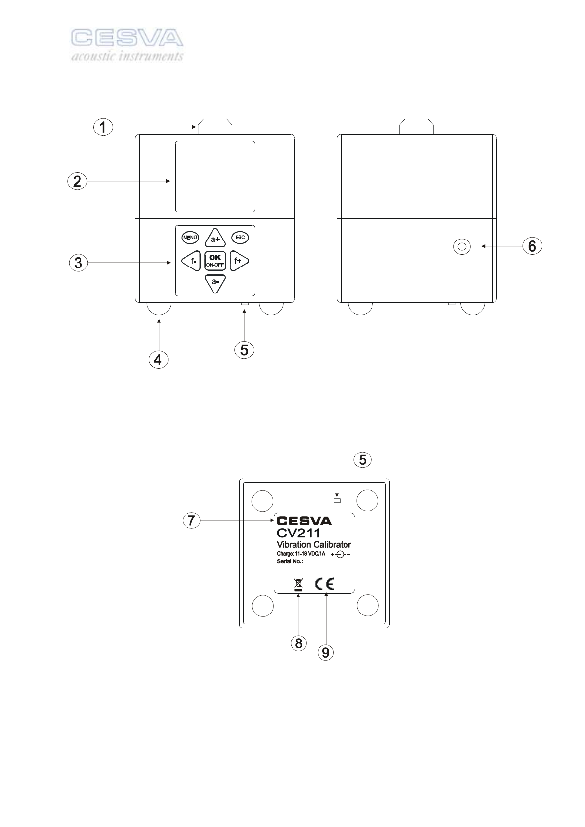
a) Place the accelerometer in the head of the CV211. It will suffice to press the
accelerometer against the calibrator head with the hand. Although it is advisable to
connect the accelerometer with a screw or by using a mounting magnet.
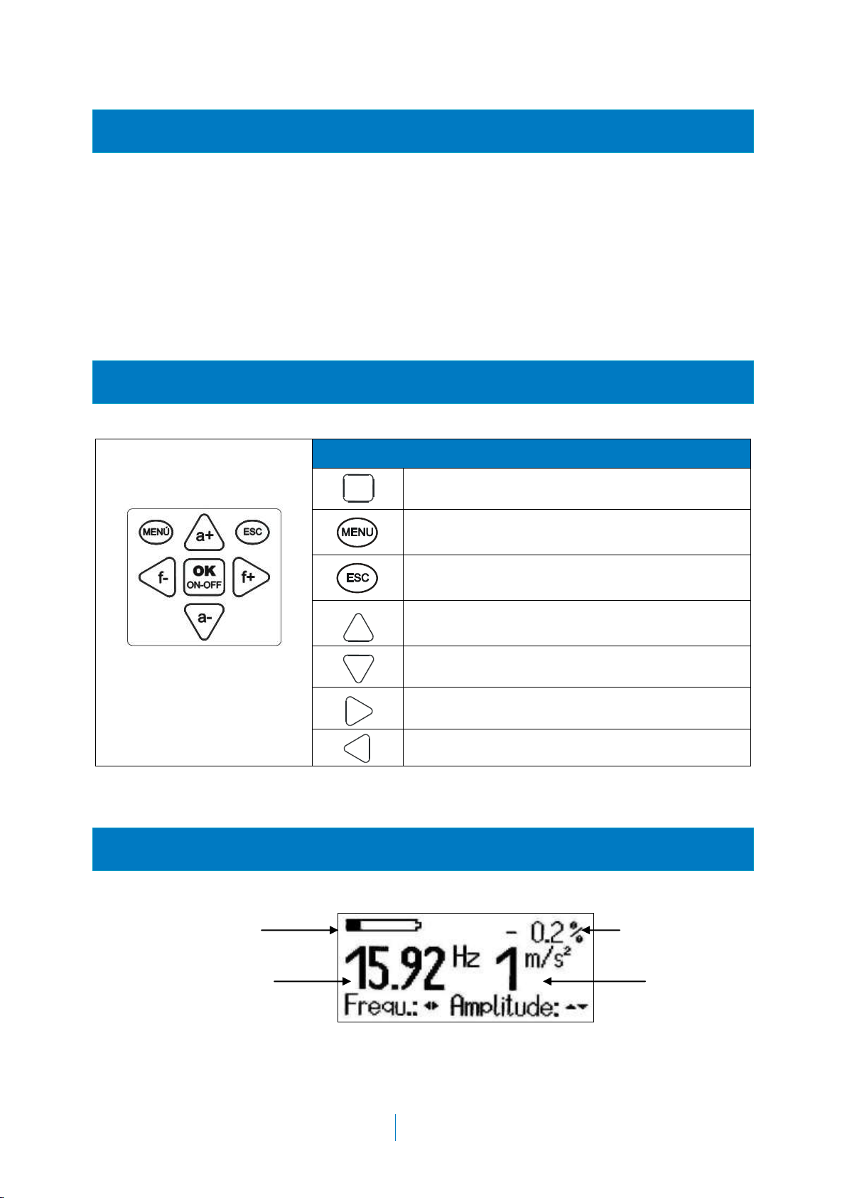
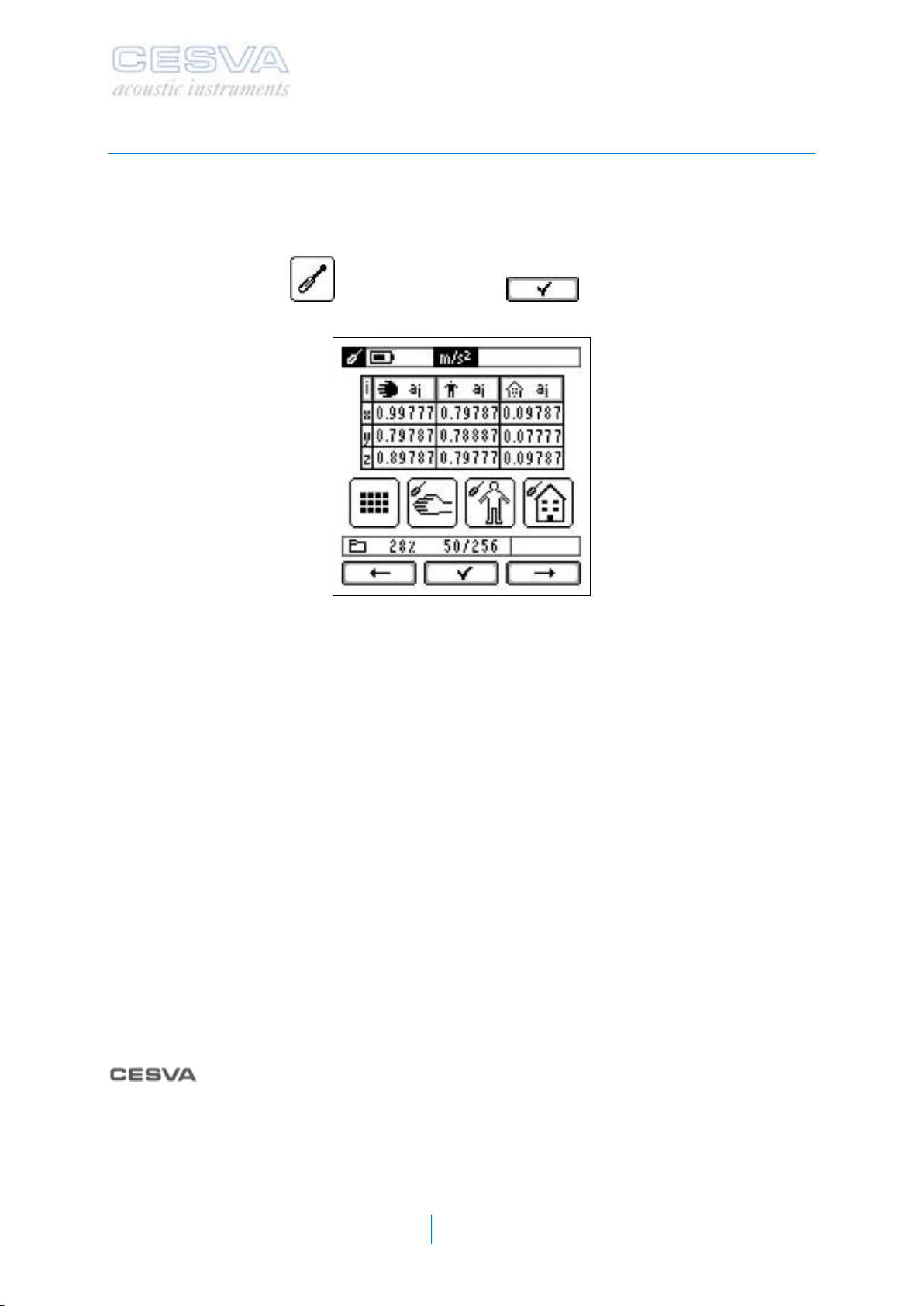
b) Take the VC431 to the main menu, and use the arrow buttons to select the sensitivity
adjustment icon and access it with the button.
The vibrometer display will show the level of RMS acceleration measured in each one of the
applications and on each one of its axes. You must know which application and which axis is
being measured at all times.
The tolerance for the reading of nominal acceleration is 5%. This means that for example if
you select an acceleration of 10 m/s2on the calibrator this acceleration value may be
between 9.5 and 10.5 m/s2for correct verification in the direction and application evaluated. If
the reading value is not in this range, the sensitivity of the vibrometer needs to be adjusted.
Otherwise the vibrometer is measuring properly and sensitivity need not be readjusted.
NOTE: The vibrometer's sensitivity can only be adjusted by authorised and technically qualified
personnel. The readjustment of sensitivity leads to loss of traceability in the calibration of the unit.
To check the Buildings / Structure AC032 accelerometer it will suffice to press the
accelerometer against the calibrator head with the hand. Note that the AC032 accelerometer
has flat surfaces all along it to facilitate placement of the accelerometer on the CV211
vibrator head.
To check the AC033 whole body accelerometer separate the sensor (metal part) from the
rest of the body (plastic part). To do so, loosen the 6 Phillips screws located at the bottom
and pull the sensor (metal part) outwards with the cable. (Do not remove the other screws).
has an optional accessory, AA144, to connect the AC033 accelerometer to the
calibrator in the three directions (X, Y and Z).
The pictures below illustrate how to check the AC031 and AC033 accelerometers.

CV211
User’s manual
9
It is very important to fix the accelerometer on the base of the head symmetrically with regard
to the vibration head, since wrong layout or placement will cause the vibration of the system
to deviate from the axis.

10
6.1.2 Verification of SC310 with module VM310
a) Couple the accelerometer to the CV211. See next figure::
b) Screw the cable to the accelerometer. See next figure:
c) Turn on the calibrator and adjust the frequency and magnitude of vibration (see point
3 of the section 6.1).
d) Next, press to access to the SC310 menu.
e) Select the option SETTINGS SENSITIVITY ADJUSTMENTS
ACCELEROMETER ADJUSTMENT from the SC310 menu
f) The acceleration level measured by the SC310 will appear on the screen, this
acceleration level is measured without frequency weighting.
The calibrator’s accuracy is 5 %. This means that if select a vibration of 10 m/s2, the correct
verification interval value is from 9.5 to 10.5 m/s2.
1
2

CV211
User’s manual
11
g) Verify that the reading value is 140 dB (corresponding to the nominal acceleration
value of 10 m/s2).
6.2 Battery
To charge the battery, connect the supplied mains plug adapter to the charge socket at the
side of the case of the CV211 calibrator.
The battery indicator is located in the upper left hand corner of the display. If the level
indicator is full, the battery level of calibrator is optimal. Instead, if the indicator is empty, the
calibrator needs to be recharged. When the battery level drops under a critical value, the
CV211 is switched off automatically.
Battery indicator
The full battery providing power for approximately 5 hours of operation.
The charging process will take about 3 hours. During the charging process the battery
indicator will be continuously moving. A permanent charging ensures long battery life.
It is possible to use the calibrator during the charging process, however this may slow down
the time needed for a full charge.
6.2.1 Battery maintenance
If constant charging is not possible, and if the calibrator is not used often, the calibrator
should be charged for one day once or twice a year.
If the typical running time can not be reached at a full charging period then you must contact
your nearest official technical service.
the operating time with a fully charged battery becomes insufficient, the battery should be
replaced. In this case, you must contact your nearest official technical service.

12
7. SETTINGS
Press the “Menu” key to enter the setup menu.
The menu has two parts:
Select “1/2 Shut-off timer”by pressing the “On/Off” key. The time for automatic shut-off can
be entered between 1 and 30 minutes by means of the “a+” and “a-“keys.
Menu item, “2/2 Calibration”is intended for factory calibration only. It is protected from
manipulation by a password.

CV211
User’s manual
13
8. TECHNICAL SPECIFICATIONS
8.1 Technical specifications
Technical specifications
Vibration frequencies
15.915 Hz
40 Hz
80 Hz
159.15 Hz
320 Hz
640 Hz
1280 Hz
Vibration magnitudes (RMS values)
1 m/s22 m/s25 m/s210 m/s220 m/s2
x x
x x x
x x x x
x x x x x
x x x x x
x x x x x
x x x x x
Accuracy of frequencies
± 0.05 %
Harmonic distortion
< 1% (15.915 Hz:< 5%)
Settling time
< 10 s
Transverse vibration
15.915 / 40 / 80 / 159.15 / 1280 Hz < 10%
320 / 640 Hz < 20%
Maximum weight (g)
Vibration frequencies
15.915 Hz
40 Hz
80 Hz
159.15 Hz
320 Hz
640 Hz
1280 Hz
Vibration magnitudes (RMS values)
1 m/s22 m/s25 m/s210 m/s220 m/s2
500 500
500 500 500
500 500 500 500
500 500 500 500 250
500 500 500 500 200
500 500 500 400 100
500 500 500 200 50
Vibration system:
Dynamic force
Maximum torque
Nominal torque
Maximum transversal force
10 N
2 Nm
1 Nm
20 Nm

14
Magnetic scatter field at shaker
< 0.2 mT
Mounting of test accelerometer
Magnetic clamp
M5 (7mm deep), 90º ± 0.5%
Temperature range
3% accuracy
5% accuracy
+10 to +40 ºC
-10 to +55 ºC
Humidity range
< 90% at 30 ºC
No condensation
Protection grade
IP 30
Power supply
Built-in accumulator
Battery features
NiMH accumulator
7.2V / 1.6 Ah
Charge socket
DIN 45323 (5.5 / 2.1)
Positive Terminal at center pin
Charge voltage
11 to 18 V DC
Charge current
< 1 A
Running hours with one battery charge
5 hours with m=100g
250 reading of 1 minute
Automatic shut-off timer
1 to 30 minutes
Dimensions
length x width x height
100 x 100 x 120 mm
Weight
2.2 kg
as an electric or electronic equipment manufacturer informs you that the
product you have purchased has been put on the market later than 13 August 2005 and
complies with 2002/96/CE and 2003/108/CE directives about Waste from Electrical and
Electronic Equipment (WEEE).
Also, the product is marked with the following symbol, which indicates that this
one is subjected to separate collection.

CV211
User’s manual
15
8.2 Included accessories
Transport briefcase
DC adaptor
Stud bolt adapters

16


Reserves the right to modify the characteristics
and accessories of this manual without a previous advice,.
Maracaibo, 6 –08030 BARCELONA (ESPAÑA)
Tel. (+34) 934 335 240 –FAX (+34) 933 479 310
e-mail: in[email protected]
www.cesva.com
Table of contents
Other CESVA Test Equipment manuals
Popular Test Equipment manuals by other brands

Capstan
Capstan Turf Sprayer Edition SharpShooter With Rate... Operator and maintenance manual

Wabtec
Wabtec Mors Smitt NIEAF SMITT RCT-C manual

Koehler
Koehler K47001 Operation and instruction manual

PNI
PNI AT6000 user manual

YOKOGAWA
YOKOGAWA DLM4038 Getting started guide

Oakton
Oakton CTSTestr 5 operating manual