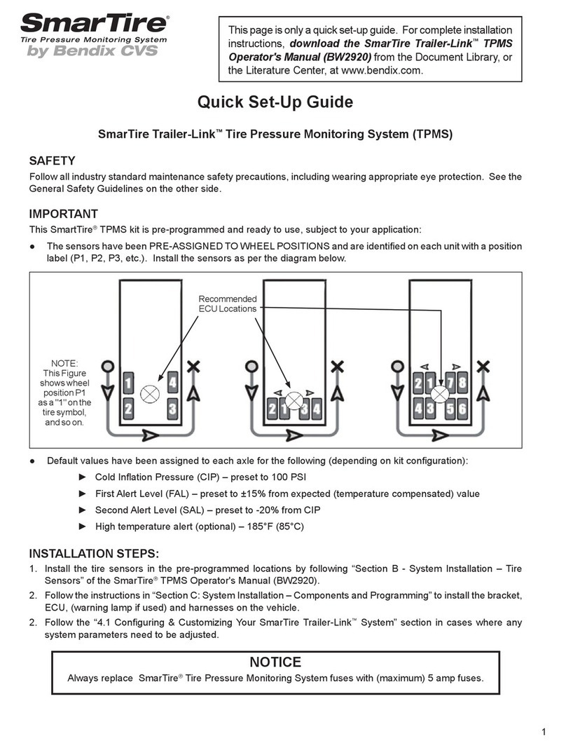
Bendix CVS SmarTire TPMS User manual

SmarTire®TPMS Low Frequency (LF) Tool User Manual
1. INTRODUCTION
The SmarTire®Tire Pressure Monitoring System (TPMS)
by Bendix CVS consists of sensors (mounted using steel
bands onto the rim of the wheels), an antenna, receiver/
Electronic Control Unit (ECU), and dash display unit or
OEM integrated display.
A Sensor is Installed
Inside Each Tire
Antenna
Receiver/ECU
Dash
Display
Each tire sensor has a unique ID code and it is
important that the system knows the ID of the sensor
used at each tire location on the vehicle.
The SmarTire Low Frequency (LF) tool is a hand-held
device used to communicate with SmarTire-brand tire
pressure monitoring system sensors.
This document will describe how the tool can be used
to program one or more new sensor ID codes into the
receiver (for example, when replacing a sensor or after
repairs/tire rotation, etc.); and how to check that all IDs
are in the expected locations when conducting a vehicle
inspection. (See BW2799 for information about other
procedures, such as loading a system conguration.)
CONTENTS
1. Introduction . . . . . . . . . . . . . . . . . . . . .1
2. Overview of the Tool Functions . . . . . . . . . . .3
3. Getting Started . . . . . . . . . . . . . . . . . . .3
4. Using the SmarTire LF Tool . . . . . . . . . . . . .3
5. Reprogramming Sensor ID Codes Using the
Smartire®LF Tool and a PC with the Bendix®
ACom®Diagnostic Software. . . . . . . . . . . . .4
6. Programming Sensor ID Codes Using the
Dash Display and the Tool. . . . . . . . . . . . . .6
6.1 To Have the System Learn a Single Tire Position .7
6.2 To Have the System Learn All the Tire Positions . .8
7. Troubleshooting . . . . . . . . . . . . . . . . . .9
Transmitter
Learn LED
Initiate LED
Low Battery
LED
On/Off/
Mode Select
Button
Initiate/
Learn
Button
Front Back
Battery
Storage
Quick Guide
THE SMARTIRE®TPMS BY BENDIX CVS LOW FREQUENCY (LF) TOOL SHOWING BUTTONS AND LEDs
NOTE: The SmarTire LF tool is compatible ONLY with
SmarTire–brand commercial vehicle tire sensors.
NOTE: For dual-wheel assemblies, it is strongly
recommended that the tire valve stems – where sensors
are typically located – be arranged 180° from each other
to avoid errors when communicating with the sensors.

2
GENERAL SAFETY GUIDELINES
WARNING! PLEASE READ AND FOLLOW THESE INSTRUCTIONS
TO AVOID PERSONAL INJURY OR DEATH:
When working on or around a vehicle, the following guidelines should be observed AT ALL TIMES:
▲Park the vehicle on a level surface, apply the
parking brakes and always block the wheels.
Always wear personal protection equipment.
▲Stop the engine and remove the ignition key
when working under or around the vehicle.
When working in the engine compartment,
the engine should be shut off and the ignition
key should be removed. Where circumstances
requirethattheengine beinoperation,EXTREME
CAUTION should be used to prevent personal
injury resulting from contact with moving,
rotating, leaking, heated or electrically-charged
components.
▲Do not attempt to install, remove, disassemble
or assemble a component until you have read,
and thoroughly understand, the recommended
procedures. Use only the proper tools and
observe allprecautions pertaining to use ofthose
tools.
▲If the work is being performed on the vehicle’s
air brake system, or any auxiliary pressurized air
systems, make certain to drain the air pressure
from all reservoirs before beginning ANY work
on the vehicle. If the vehicle is equipped with a
Bendix®AD-IS®air dryer system,aBendix®DRM™
dryer reservoir module, or a Bendix® AD-9si®air
dryer, be sure to drain the purge reservoir.
▲Following the vehicle manufacturer’s
recommended procedures, deactivate the
electrical system in a manner that safely removes
all electrical power from the vehicle.
▲Never exceed manufacturer’s recommended
pressures.
▲Never connect or disconnect a hose or line
containing pressure; it may whip and/or cause
hazardous airborne dust and dirt particles. Wear
eye protection. Slowly open connections with
care, and verify that no pressure is present. Never
remove a component or plug unless you are
certain all system pressure has been depleted.
▲Use only genuine Bendix®brand replacement
parts, components and kits. Replacement
hardware, tubing, hose, ttings, wiring, etc. must
be of equivalent size, type and strength as original
equipment and be designed speci cally for such
applications and systems.
▲Components with stripped threads or damaged
parts should be replaced rather than repaired.
Do not attempt repairs requiring machining or
welding unless speci cally stated and approved
by the vehicle and component manufacturer.
▲Prior to returning the vehicle to service, make
certain allcomponents and systems are restored
to their proper operating condition.
▲For vehicles with Automatic Traction Control
(ATC), the ATC function must be disabled (ATC
indicator lamp should be ON) prior to performing
any vehicle maintenance where one or more
wheels on a drive axle are lifted off the ground
and moving.
▲The power MUST be temporarily disconnected
from the radar sensor whenever any tests USING
A DYNAMOMETER are conducted on a vehicle
equipped with a Bendix® Wingman®system.
▲You should consult the vehicle manufacturer's operating and service manuals, and anyrelated literature,
in conjunction with the Guidelines above.

3
Initiate/Learn Button: After selecting the initiate or
learn mode, press this button to request the
appropriateresponsefrom a sensor. Initiation
transmissions are used to obtain new sensor
readings for the SmarTire gauge or the
diagnostics software.
Low Battery LED: The low battery LED
will ash amber once every second when
thetool is onandtheonboard9-Voltbattery
isnearempty. Approximately20 additional
Initiate/Learn operations can be performed after the
battery LED blinks for the rst time. The battery LED will
lightupsolid amber during the shut downprocesstosignal
that the user can release the ON/OFF button.
3. GETTING STARTED
TheSmarTireTPMS Low Frequency(LF)tool is powered
byastandard9-Voltbattery.To install the battery,openthe
battery access panel on the back of the tool and connect
the supplied battery to the 9-Volt battery connector.
4. USING THE SMARTIRE LF TOOL
Read and understand the General Safety Guidelines
on page two of this document before beginning any
maintenance work on a vehicle.
IMPORTANT
It is important to make sure that there is no loss of
power to the SmarTire TPMS during the Learn Sensor
procedure. Power interruptions will result in some -
and potentially all - stored sensor location information
being lost, requiring the technician to start over again.
A. To switch on the SmarTire LFTool, press and hold
the On/Off/Mode Select button ( ) for two (2)
seconds.
B. Enter the Learn ( ) or the Initiate ( )
Mode by toggling the On/Off/Mode
Selectswitch ( ) and thenpressingthe
Mode Select button.
C. Hold the tool approximately two(2)in. (5cm) away
from the tire’s surface, at the center of the tire’s
sidewall,closetothevalvestem. (Therecommended
location for all SmarTire TPMS sensors is at the
valve and rim-mounted labels indicate their
location). Donot touch therimwith the tool. Press
andrelease the Initiate/Learn ( )button (a single
beepwillbeheard)andholdthe tool in place for
ve (5) seconds until four (4) quick beeps are heard
tosignalthatthetoolandsensorhavecommunicated
successfully.
2. OVERVIEW OF THE TOOL FUNCTIONS
Transmitter: The top part of the tool must be pointed
towards the tire to communicate with the sensor. See the
diagram below. For dual-wheel assemblies it is strongly
recommended that the tires are installed with their valve
stems arranged 180° from each other to help make sure
that the transmission reaches the correct sensors.
OUTBOARD
TIRE INBOARD
TIRE
LF TOOL
TRANSMITTER
ON/OFF/Mode Select Button: Press and hold this
button for two (2) seconds to power ON the tool. The tool
will sound a beep and the Initiate LED will illuminate to
show that the tool is ON. To toggle the tool
betweenthesensor Initiate and sensorLearn
functions, press the button briey. The green
LED for the current mode will be illuminated.
To shut down the tool, press and hold the
button for four (4) seconds. The battery LED
illuminates to show that you can now release the button.
Initiate LED: The Initiate LED will be ON (green) as long
astheInitiate Modeisselected. WhenpressingtheInitiate
button, the LED will blink rapidly for ve (5) seconds and
then change to one (1) blink per second after
the initiation has been completed. In service,
thesensorautomatically communicates every
3-5 minutes, however the tool prompts an
immediate response.
Learn LED: TheLearn LEDwillbeON(green)as long as
theLearnMode is selected. Learn transmissionsareused
whenreprogramming sensor ID codesintotheSmarTire®
TPMS receiver, either by using the PC-based
Bendix®ACom®Diagnostic software, or by
using the dash-mounted display. When
pressing the Learn button, the LED will blink
rapidly for ve (5) seconds and then change
to one (1) blink per second after the Learn transmission
has been completed. Upon being prompted, the sensor
communicates its unique ID code to the receiver.

4
5. REPROGRAMMING SENSOR ID CODES
USING THE SMARTIRE®LOW FREQUENCY
(LF) TOOL AND A PC WITH THE BENDIX®
ACOM®DIAGNOSTIC SOFTWARE
IMPORTANT
It is important to make sure that there is no loss
of power to the SmarTire®TPMS during the Learn
Sensor procedure. Power interruptions will result in
some - and potentially all - stored sensor location
information being lost, and the procedure will have
to be repeated.
For SmarTire TPMS system maintenance,
Version 6.5 (or higher) of the Bendix®ACom®
Diagnostic Software is required.
Read and understand the General Safety Guidelines
on page two of this document before beginning any
maintenance work on the vehicle.
Bendix ACom Diagnostic Software is an RP-1210
compliant PC-based diagnostic software program that
provides the highest level of diagnostic support for the
SmarTire TPMS system. The latest version of the
software is available for download at www.bendix.com.
These instructions will cover the use of the software to
program sensor IDs. For details about other functions
such as: setting system warning parameters; retrieving
Diagnostic Trouble Codes (DTCs); and verifying System
congurations, please see BW2799.
Connect the SmarTire ECU in the receiver to your PC
throughthevehicle’sdiagnosticconnectorviaanRP-1210
compliant communications device.
Laptop
Computer
USB
Cable
Noregon®Adapter
J2497 (PLC) or
J1939
To have the system learn a sensor position:
A. ConnectthePCto the vehicle and open theBendix
ACom Diagnostic Software. Select TPMS (for
tractorsystems)orBendix™Trailer-Link™(fortrailer
systems) module and select the “Start with ECU”
button.
B. Onceconnected to the ECU,select
theSetupmodebypressingtheSet
Up icon displayed here.
Select which sensor you would like to replace by
clicking on the tire icon for that position. The tire
symbol will be highlighted (it changes to green).
See the illustration at the top of the next page.
C. Select the Learn Sensor button in the sensor
conguration box (bottom right of the screen).
D. Thescreen will indicatethatthesystemis searching
for a sensor.
E. The technician has three (3) minutes to use the
SmarTire LF Tool to send a request to the sensor
in that tire, to transmit its ID. Switch on the
SmarTire LF tool by pressing and holding the On/
Off/Mode Select button ( ) for 2 seconds. Toggle
the tool mode to the Learn Sensor function by
pressingtheOn/Off/ModeSelect button ( ) again.

5
F. HoldtheSmarTire®TPMSLowFrequency(LF)tool
withthetransmissionendpointedtowardsthetire’s
sidewall adjacent to the sensor’s location
approximately two (2) inches away from the tire’s
surface.Pressand release the Initiate/Learn Button
( )(a single beep willbeheard) and keep thetool
in place for ve (5) seconds until four (4) quick
beeps are heard.
Note: Do not hold down the Initiate/Learn button ( ).
G. Oncetriggered,itcan take up to 30seconds forthe
system to receive the transmission and complete
the learn process. The ID code edit box for the
wheel position will update with the new ID code
and the Bendix®ACom®symbol for that location
will turn yellow after a successful communication.
H. Repeat this process for all the wheel positions that
need to be programmed.
Note:Thefollowingwarning may appearifyouarelearning
more than one tire position:
“Learn process may fail if sensors are relocated or
swapped and the conguration is not written to ECU.
Would you like to continue the learn process anyway?”
Press the OK button to continue the process.
I. It is important to save the changes you have just
made. After the system has learned the ID codes
for the targeted wheels, select the Write to ECU
button to save them.
A dialog box will appear showing the progress.
Look for the following conrmation dialogue box.
“The conguration has been successfully written to the
ECU.”

6
6. PROGRAMMING SENSOR ID CODES
USING THE DASH DISPLAY AND THE TOOL
IMPORTANT
As stated earlier, it is important to make sure that
there is no loss of power to the SmarTire®TPMS
during the Learn Sensor procedure.
Note: Not all functionality may be accessible using the
dash display; if a menu item shown here is not visible on
your display, it may be disabled, or not available because
ofthe version of dashdisplaybeingused. UsetheBendix®
ACom®Diagnosticsoftwareforaccess to full functionality.
TPMS Ready
Left
(typical action:
“scroll down”)
Right
(typical action:
“scroll across”)
This icon is only
displayed when
Trailer TMPS is
detected
Center
(typical action: “select”)
For systems that are congured to require a password:
Press and hold the center button for two seconds and
the display will show a password entry screen.
To enter a password, press the left button to scroll
the rst digit from 9 to 0. When the correct digit is
displayed, press the right button to move to the
next digit in sequence. Repeat this action until all
four digits are entered correctly and then push the
right button to enter the password. If the password
is correct, the display will enter Setup Mode. If the
password is incorrect, the display will indicate that
the wrong password was entered and return to the
password entry screen.
NOTE: If the system is not congured to use a password,
the system will go directly to the setup mode.
To enter the Setup Mode, on the dash display press the
center button repeatedly until the TPMS Ready screen
is displayed.
Above: With no active Diagnostic Trouble Codes (DTCs).
Above: If there are any active pressure or temperature
DTCs present, a symbol with an exclamation point inside
a triangle will be displayed.
When in Setup Mode, scroll to the “Learn Sensors” menu
item. Press the right button to select the Learn Sensor
function.
Depending on the version of the display installed, the
following screen may vary.
Go to 6.1
Go to 6.2
In cases where the “Learn All Tires” option is not shown,
the vehicle has an older version of the dash display, and
the technician will have to repeat Section 6.1 as many
times as needed to learn the missing tire IDs.

7
6.1 TO HAVE THE SYSTEM LEARN A SINGLE
TIRE POSITION
IMPORTANT
As stated earlier, it is important to make sure that
there is no loss of power to the SmarTire®TPMS
during the Learn Sensor procedure.
6.1.1 Press the right button on the dash display to select
the learn single tire option. The display will now
show the rst axle on the vehicle. Press the left
button to scroll through the axles, and then use the
right button, if necessary, to scroll until the desired
tire is selected. Then press and hold the center
button for two seconds.
6.1.2 The next screen displayed will depend on the
display and receiver versions installed.
Select the Hand Tool option (scroll down using the
left button, then the right button to select it).
Earlier versions of software may instead take you
directly to the next step.
6.1.3 The screen will then show “Deleting Tire” and the
selected wheel position will ash.
6.1.4 WhentheID for the selectedtire hasbeendeleted,
the screen will show “Learn in Progress”.
6.1.5 The technician has three (3) minutes to use the
SmarTire Low Frequency (LF) Tool to send a
request to the sensor inside that tire, to transmit
its ID.
To do this, hold the SmarTire LF tool with the
transmissionend pointed towards thetire’ssidewall
adjacenttosensor’slocationapproximately two (2)
inches away from the tire’s surface. Press and
releasetheInitiate/Learn( ) Button (a single beep
will be heard) and keep the tool in place for
ve (5) seconds until four (4) quick beeps are heard.
Note: Do not hold down the Initiate/Learn ( ) button.
6.1.6 After the receiver registers the transmission, it can
take up to 30 seconds for the learn process to be
completed. Look for the “Learn Complete” screen
to be displayed.
LEARN COMPLETE
IMPORTANT: Press the centerbuttononcetosave
the changes and exit the “Learn” function.
PressthecenterbuttonrepeatedlytoexittheSetup
Mode.
Potential error messages are:
Learn Time Out. This may occur when the three (3)
minutewindowforreceivingtheresponse from the sensor
is exceeded.
Duplicate Sensor ID. When the ID code received is
already being used on the vehicle.
See the Troubleshooting Section (Section 7) for more
information.

8
6.2 TO HAVE THE SYSTEM LEARN
ALL THE TIRE POSITIONS
IMPORTANT
As stated earlier, it is important to make sure that
there is no loss of power to the SmarTire®TPMS
during the Learn Sensor procedure.
To learn alltirepositions,follow the steps under Section 6
above, but instead of selecting the “Learn Single Tire”
option, use the “Learn All Tires” option instead. (The
display may vary.)
When learning all tire positions, the display will expect
the responses from the tire sensors be received starting
with the front left tire and moving around the vehicle in a
counterclockwise pattern based upon the stored vehicle
conguration. (Note that a spare tire may also be included
in the tires to be identied).
Above tractors, below trailers
For dual tire axles, the inner tire is learned rst and then
the outer tire. Follow the prompts on the display as it will
indicate the current position to be learned.
6.2.1 The next screen will permit you to select the “Hand
Tool” option. (The display may vary.)
These instructions will cover the use of the hand
tool to program the sensor IDs. For details about
the Manual ID entry option, please see BW2799.
6.2.2 The next screen will prompt you to choose to
overwrite the existing prole.
Select “Yes” (press the right button) to continue.
The “Initializing Prole” screen will display the
system’s progress in erasing the old prole.
6.2.3 Wait for the status bar to compete and the “Learn
in Progress” message to be displayed before
continuing.
TheIDforthewheelpositiontobeprogrammedwill
bedisplayednext and the SmarTireLowFrequency
(LF) Tool must be used at that location within three
(3) minutes.
LEARN COMPLETE
6.2.4. Usethetechniquedescribed in 6.1.5 to request the
sensor to transmit its ID to the receiver.
6.2.5 Check that the “Learn Complete” has been
displayed (this may take up to 30 seconds) and
then move to the next tire position to be learned.
Repeat these steps until all wheel positions are
programmed.
6.2.6 IMPORTANT: Press the center button once to save
the changes and exit the “Learn” function.
PressthecenterbuttonrepeatedlytoexittheSetup
Mode.
Potential error messages are:
Learn Time Out. This may occur when the three (3)
minutewindowforreceivingtheresponse from the sensor
is exceeded.
Duplicate Sensor ID. When the ID code received is
already being used on the vehicle.
See the Troubleshooting Section (Section 7) for more
information.

9
7. TROUBLESHOOTING
The following messages may be displayed at the end of
the Learn process if it was not completed successfully:
A. Learn Time Out. The receiver did not receive an
expectedresponsefrom a sensor within three(3)minutes
after being requested to learn a tire, and so the system
“timed- out”. Re-attempt to communicate at least twice.
If unsuccessful, a sensor may be pointing directly down
into the ground, or away from the Gateway or Antenna,
causing the signal reception to be disrupted. In these
cases, it may be useful to move the vehicle forward or
backward about a half-turn of the wheels, to reposition
the sensor, and then retry.
It can be useful to look to see if the tire stems for dual-
wheel assemblies are installed with their valve stems
arranged 180° from each other, as recommended. If still
unsuccessful,tryto initiate the sensoratthebottom of the
wheel, no matter where the valve stem is located. If this
attempt was successful, rotate the wheel 180 degrees
forward and initiate the sensor again at the BOTTOM of
the wheel. If the second initiation also provided a result,
itis evidence ofa broken cradle and/orstrap. The sensor
is simply falling to the lowest point in the wheel after each
rotation. Removethetireandreplacethecradleandstrap.
Dependingonthedamagedonetothesensor itself, it may
simply be pressed into a new cradle for reuse, however,
do not reuse the strap.
It is also important to check that the tool is held about
two(2) inches from the tire during the procedure – and
not touching the rim.
B. Duplicate Sensor ID. Thesensor ID that was received
for the wheel position is already programmed into the
system at another wheel position. (This may occur when
rotatingwheelsifthe original set of locations hasnot been
erased.) Repeat the process, ensuring you are initiating
the sensor you wish to learn. Take care when working
with dual tire assemblies to communicate with the correct
tire position.
It can be useful to look to see if the tire stems for dual-
wheel assemblies are installed with their valve stems
arranged 180° from each other, as recommended. You
can verify the location of the sensor in most cases, by
lookingforthe label attached to therimduringinstallation.
If still unsuccessful, try to initiate the sensor at the bottom
ofthewheel,no matter where the valve stemis located. If
thisattemptwassuccessful,rotatethewheel180degrees
forward and initiate the sensor again at the BOTTOM of
the wheel. If the second initiation also provided a result,
itis evidence ofa broken cradle and/orstrap. The sensor
is simply falling to the lowest point in the wheel after each
rotation. Removethetireandreplacethecradleandstrap.
Dependingonthedamagedonetothesensor itself, it may
simply be pressed into a new cradle for reuse, however,
do not reuse the strap.
For more in-depthtroubleshooting, consult the SmarTire®
TirePressureMonitoring System (TPMS) byBendixCVS
Operator’sManual (BW2799), availablefordownloadfrom
the Bendix website www.bendix.com.

10
FCC NOTICE
This device complies with Part 15 of the FCC Rules. The
SmarTire®TPMS Low Frequency (LF) tool is a Part 15
low-power transmitter below 1705 kHz. The device has
a rated RF power output of less than 0.2 micro Watts.
Due to the frequency range of the transmitter – and the
low-level of output power – the device is not subject to
the routine RF exposure valuation as per Section 2.1093
of the FCC rules.
Operation is subject to the following two conditions:
1. Thisdevicemay not cause harmfulinterference; and,
2. This device must accept any interference received,
including interference that may cause undesired
operation.
Thisequipment has been tested andfoundtocomply with
the limits for a Class B digital device, pursuant to Part 15
of the FCC Rules. These limits are designed to provide
reasonable protection against harmful interference in a
residential installation. This equipment generates, uses
andcanradiate radio frequencyenergyand,ifnotinstalled
and used in accordance with the instructions, may cause
harmful interference to radio communications. However,
there is no guarantee that interference will not occur in a
particular installation.
If this equipment does cause harmful interference to
radio or television reception, which can be determined by
turning the equipment off and on, the user is encouraged
to try to correct the interference by one, or more, of the
following measures:
• Reorient or relocate the receiving antenna.
• Increase the separation between the equipment and
the receiver.
• Connect the equipment into an outlet on a circuit
different from that to which the receiver is connected.
• Consult the dealer or an experienced radio/TV
technician for help.
Changes or modifications to this device without the
expressapprovalof the manufacturer may voidtheuser’s
authority to use this device.
Duplication of this document in whole or in part for any
purposes other than those for which it was originally
intended, without the written approval of Bendix
Commercial Vehicle Systems LLC is strictly prohibited.
Theinformationprovided in thismanualisforinformational
purposes only and is subject to change without notice
andshould not beconstruedas a commitmentby Bendix.
Bendixassumesnoresponsibilityor liability for any errors
or inaccuracies that may appear in this publication.
EUROPEAN REGULATIONS
This device complies with R&TTE 1999/5/EC through
harmonized standards (EN301 489-1 and EN330 330-1).
The equipment has been tested and found to comply
with the above directive and in addition it meets the
requirements for low powered transmitters/receivers
as dened by the relevant radio approval authority and
complies with low voltage directive 73/23/EEC. The
directive is designed to provide reasonable protection
against harmful interference or susceptibility. Changes
made to this device without the express approval of the
manufacturer may void the user’s authority to use this
device
RSS210, RSSGEN
This device complies with Industry Canada’s licence-
exempt RSSs. Operation is subject to the following two
conditions:
1. This device may not cause interference; and
2. This device must accept any interference, including
interference that may cause undesired operation of
the device.
TRADEMARKS
The SMARTIRE trademark is owned by Bendix
Commercial Vehicle Systems LLC. Any references in
this catalog to any other company or trademark are
solely for identication purposes. The trademarks are
the property of their respective companies and are not
afliated with or endorsing Bendix Commercial Vehicle
Systems LLC. Bendix Commercial Vehicle Systems
LLC does not represent any parts shown as products
manufactured or remanufactured by the companies so
named herein.

11
NOTES

12
901 Cleveland Street • Elyria, Ohio 44035 • 1-800-AIR-BRAKE (1-800-247-2725)
6900 Graybar Road #2110 • Richmond, British Columbia, Canada V6W 0A5 • 604-242-7400
®
BW2820 ©2015 Bendix Commercial Vehicle Systems LLC, a member of the Knorr-Bremse Group • 11/15 • All Rights Reserved • www.bendix.com
Table of contents
Other Bendix CVS Measuring Instrument manuals
Popular Measuring Instrument manuals by other brands
PCB Piezotronics
PCB Piezotronics 320C17 Installation and operating manual

Bosch
Bosch DLE 70 Professional Original instructions

Agilent Technologies
Agilent Technologies TapeStation 4200 Software & User Information
PCE Instruments
PCE Instruments PCE-HT 70 user manual
Environmental Express
Environmental Express IAQ 15 Connect Operating instructions manual

Ahlborn
Ahlborn ALMEMO 2490-1A operating instructions
