Sea-Bird Electronics SBE 45 MicroTSG User manual

Sea-Bird Electronics, Inc.
13431 NE 20th Street
Bellevue, Washington 98005 USA
Tel: 425/643-9866
Fax:425/643-9954
SBE 45 MicroTSG
THERMOSALINOGRAPH
Conductivity and Temperature Monitor
with RS-232 Interface
Serial Number: 4566782-0402
User Manual, Version 015

This page intentionally left blank.

SEA-BIRD ELECTRONICS, INC.
13431 NE 20th St.
Bellevue, Washington 98005 USA
Phone: (425) 643 9866
Fax: (425) 643 9954
Email: [email protected]
SBE 45 MICRO-TSG OPERATING AND REPAIR MANUAL
TABLE OF CONTENTS
Manual Generation Date....................................................................................................................................................................................................................................
1
Limited Liability Statement...............................................................................................................................................................................................................................
2
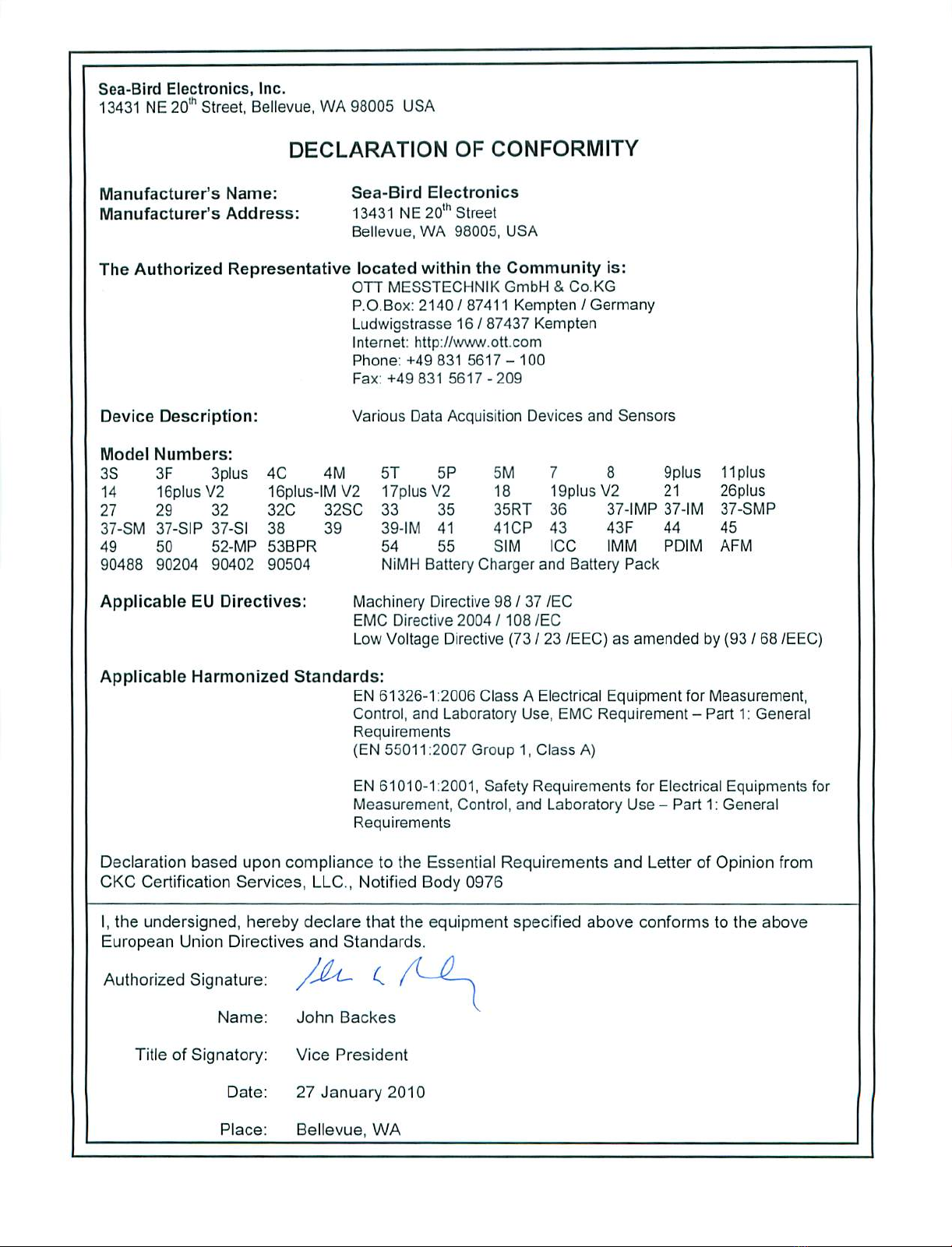
Declaration of Conformity.................................................................................................................................................................................................................................
4
SBE 45 Configuration - S/N 0402...........................................................................................................................................................................................................................
5
SBE 45 Manual - Version 015...............................................................................................................................................................................................................................
6
SBE 45 Reference Sheet - Version 007......................................................................................................................................................................................................................
59
SBE 45 Specification Sheet................................................................................................................................................................................................................................
61
PN 90402 Manual - Version 008.............................................................................................................................................................................................................................
63
SBE 45 Calibrations.......................................................................................................................................................................................................................................
95
Appnotes..................................................................................................................................................................................................................................................
98
Drawings..................................................................................................................................................................................................................................................
125
Warranty..................................................................................................................................................................................................................................................
136
Service Request Form......................................................................................................................................................................................................................................
139

Manual Generation Date: 13 February 2012
1

L I M I T E D L I A B I L I T Y S T A T E M E N T
Extreme care should be exercised when using or servicing this equipment. It should be used or
serviced only by personnel with knowledge of and training in the use and maintenance of
oceanographic electronic equipment.
SEA-BIRD ELECTRONICS, INC. disclaims all product liability risks arising from the use or servicing of
this system. SEA-BIRD ELECTRONICS, INC. has no way of controlling the use of this equipment or of
choosing the personnel to operate it, and therefore cannot take steps to comply with laws pertaining to
product liability, including laws which impose a duty to warn the user of any dangers involved in
operating this equipment. Therefore, acceptance of this system by the customer shall be conclusively
deemed to include a covenant by the customer to defend, indemnify, and hold SEA-BIRD
ELECTRONICS, INC. harmless from all product liability claims arising from the use of servicing of this
system.
2

This page intentionally left blank.
3
4

Instrument Configuration:
Serial Number 37SI64195-8524
Pressure Sensor None
Firmware Version 3.0j
Memory 8192Kb
Interface Type RS-232
Conductivity Range 0-7 S/m
Baud Rate 9600, 8 data bits, no parity
Zero Conductivity 2491.031 Hz
Maximum Depth 7000 meters
SBE45 MicroTSG
(Thermosalinograph)
Conductivity & Temperature Monitor
with RS-232 Serial Interface
CAUTION - This instrument is not intended for
underwater use.
Maximum Depth 0
Power Up Jumper Autopower Pins 1 & 2
Baud Rate 4800
Conductivity Range 0-7 S/m
Interface Type RS-232
Firmware Version V 1.1b
Serial Number 4566782-0402
Instrument Configuration:
5

SBE 45 MicroTSG
(Thermosalinograph)
Conductivity and Temperature Monitor
with RS-232 Interface
Note: NEW ADDRESS
as of January 18, 2010
User’s Manual
Sea-Bird Electronics, Inc.
13431 NE 20th Street
Bellevue, Washington 98005 USA
Telephone: 425/643-9866 Manual Version #015, 01/26/10
Fax: 425/643-9954 Firmware Version 1.1b and later
E-mail: seabir[email protected] Seasave V7 Version 7.20a and later
Website: www.seabird.com SBE Data Processing Version 7.20a and later
6

2
Limited Liability Statement
Extreme care should be exercised when using or servicing this equipment. It should be used or serviced
only by personnel with knowledge of and training in the use and maintenance of oceanographic
electronic equipment.
SEA-BIRD ELECTRONICS, INC. disclaims all product liability risks arising from the use or servicing
of this system. SEA-BIRD ELECTRONICS, INC. has no way of controlling the use of this equipment
or of choosing the personnel to operate it, and therefore cannot take steps to comply with laws
pertaining to product liability, including laws which impose a duty to warn the user of any dangers
involved in operating this equipment. Therefore, acceptance of this system by the customer shall be
conclusively deemed to include a covenant by the customer to defend, indemnify, and hold SEA-BIRD
ELECTRONICS, INC. harmless from all product liability claims arising from the use or servicing of
this system.
7

Table of Contents SBE 45
3
Table of Contents
Section 1: Introduction ........................................................................ 5
About this Manual .............................................................................................5
Quick Start .........................................................................................................5
Unpacking MicroTSG........................................................................................6
Section 2: Description of MicroTSG .................................................. 7
System Description ............................................................................................7
Specifications.....................................................................................................9
Dimensions and Connector ..............................................................................10
Sample Timing.................................................................................................11
Baud Rate, Cable Length, Power, and Data Transmission Rate ......................12
Remote Temperature Sensor (optional) ...........................................................14
Section 3: Installing System .............................................................. 15
Installing Software...........................................................................................15
System Schematic and Installation Guidelines ................................................16
Power-Up Jumper Check .................................................................................18
Installing MicroTSG ........................................................................................19
Section 4: Setting Up MicroTSG ...................................................... 20
Communications Test and Setup......................................................................20
Sampling Modes ..............................................................................................24
Polled Sampling........................................................................................24
Autonomous Sampling .............................................................................25
Serial Line Synchronization (Serial Line Sync)........................................26
Timeout Description ........................................................................................26
Command Descriptions....................................................................................27
Data Output Format .........................................................................................32
Setting Up Configuration (.xmlcon or .con) File .............................................33
Section 5: Operating System ............................................................. 34
Acquiring Real-Time Data with Seasave.........................................................34
Processing Data................................................................................................36
Section 6: Routine Maintenance and Calibration .......................... 37
Corrosion Precautions......................................................................................37
Cleaning and Storage .......................................................................................37
Replacing Anti-Foulant Device (SBE 45)........................................................39
Sensor Calibration............................................................................................40
Section 7: Troubleshooting................................................................ 41
Problem 1: Unable to Communicate with MicroTSG......................................41
Problem 2: Nonsense or Unreasonable Data....................................................41
Problem 3: Salinity Lower than Expected .......................................................41
Glossary .............................................................................................. 42
8

Table of Contents SBE 45
4
Appendix I: Functional Description................................................. 43
Sensors.............................................................................................................43
Sensor Interface ...............................................................................................43
Appendix II: Electronics Disassembly/Reassembly ........................ 44
Appendix III: Command Summary ................................................. 45
Appendix IV: AF24173 Anti-Foulant Device .................................. 47
Appendix V: Replacement Parts ...................................................... 51
Index.................................................................................................... 52
9

Section 1: Introduction SBE 45
5
Section 1: Introduction
This section includes a Quick Start procedure, and photos of a standard
SBE 45 MicroTSG shipment.
About this Manual
This manual is to be used with the SBE 45 MicroTSG Conductivity and
Temperature Monitor. It is organized to guide the user from installation
through operation and data collection. We’ve included detailed specifications,
command descriptions, maintenance and calibration information, and helpful
notes throughout the manual.
Sea-Bird welcomes suggestions for new features and enhancements of our
products and/or documentation. Please contact us with any comments or
suggestions (seabird@seabird.com or 425-643-9866). Our business hours are
Monday through Friday, 0800 to 1700 Pacific Standard Time (1600 to 0100
Universal Time) in winter and 0800 to 1700 Pacific Daylight Time (1500 to
0000 Universal Time) the rest of the year.
Quick Start
Follow these steps to get a Quick Start using the MicroTSG.
The manual provides step-by-step details for performing each task:
1. Perform pre-check procedures (see Sections 3 and 4):
A. On the Configuration Sheet (in the manual), check the factory-set
power-up mode jumper setting. For a description of how the jumper
setting affects operation, see Power-Up Jumper Check in Section 3:
Installing System.
B. Test power and communications.
C. Establish setup and operating parameters.
D. Check status (DS) and calibration coefficients (DC) to verify setup.
2. Deploy the MicroTSG (see Sections 3,4, and 5):
A. Verify the AF24173 Anti-Foulant Device is installed.
B. Install the MicroTSG.
C. Send commands to run the system.
10

Section 1: Introduction SBE 45
6
Unpacking MicroTSG
Shown below is a typical MicroTSG shipment.
Spare parts kit
MicroTSG
MicroTSG User Manual
Conductivity cell cleaning
solution (Triton X-100)
I/O cable
Software, and Electronic Copies of
Software Manuals and User Manual
11

Section 2: Description of MicroTSG SBE 45
7
Section 2: Description of MicroTSG
This section describes the functions and features of the MicroTSG, including:
•System description
•Specifications
•Dimensions and connector
•Sample timing
•Baud rate, cable length, and power requirements
•Optional remote temperature sensor
System Description
The SBE 45 MicroTSG is an externally powered, high-accuracy, conductivity
and temperature monitor, designed for shipboard determination of sea surface
(pumped-water) conductivity and temperature.
Communication with the MicroTSG is over an internal, 3-wire, RS-232C link,
providing real-time data transmission. Commands can be sent to the
MicroTSG to provide status display, data acquisition setup, data acquisition
and display, and diagnostic tests. User-selectable operating modes include:
•Polled sampling – On command, the MicroTSG takes one sample and
sends the data to the computer.
•Autonomous sampling – At pre-programmed intervals, the MicroTSG
samples and sends the data to the computer. The MicroTSG does not enter
quiescent (sleep) state between samples.
•Serial Line Sync - A pulse on the serial line causes the MicroTSG to
wake up, sample, and enter quiescent (sleep) state automatically.
Calibration coefficients stored in EEPROM allow the MicroTSG to transmit
data in engineering units. The MicroTSG retains the temperature and
conductivity sensors used in the SBE 21 Thermosalinograph, but has improved
acquisition electronics that increase accuracy and resolution, and lower power
consumption. The MicroTSG’s aged and pressure-protected thermistor has a
long history of exceptional accuracy and stability (typical drift is less than
0.002 °C per year). Electrical isolation of the conductivity electronics
eliminates any possibility of ground-loop noise.
The MicroTSG’s internal-field conductivity cell is unaffected by external
fouling. A plastic cup with O-ring retainer at one end of the cell retains the
expendable AF24173 Anti-Foulant Device.
12
Section 2: Description of MicroTSG SBE 45
8
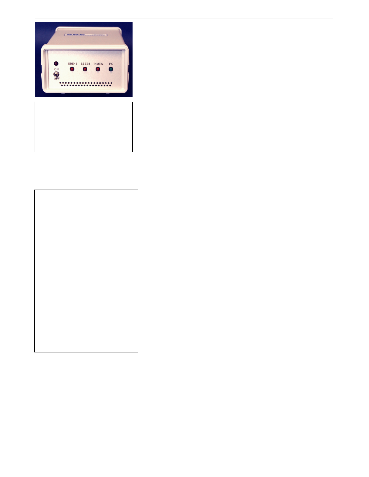
An optional AC- or DC-powered 90402 - SBE 45 Power, Navigation, and
Remote Temperature Interface Box provides:
•Power and an opto-isolated RS-232C interface for the MicroTSG
•An opto-isolated NMEA receiver for an optional NMEA navigation
device which supports NMEA 0183 protocol, outputting data in GGA,
GLL, RMA, RMC, or TRF format (NMEA navigation device not supplied
by Sea-Bird)
•Power and an RS-232C interface for an optional SBE 38 remote
temperature sensor
•An RS-232C computer interface
Decoded Latitude, Longitude, date, and time and SBE 38 temperature data are
appended to the MicroTSG data stream in the Interface Box. The data is
transmitted to the computer for storage and/or display.
The MicroTSG is supplied with a powerful 2000/XP software package,
Seasoft©V2, which includes:
•SEATERM – terminal program for easy communication and data
retrieval, can send commands to the MicroTSG to provide status display,
data acquisition setup, data display and capture, and diagnostic tests.
•Seasave V7 – program for acquiring, saving, and displaying real-time or
archived data.
•SBE Data Processing – program for calculation and plotting of
conductivity, temperature, data from auxiliary sensors, and derived
variables such as salinity and sound velocity.
Notes:
•Help files provide detailed
information on the software.
•Software manuals on CD-ROM
contain detailed information on
Seasave V7 and SBE Data
Processing.
•Sea-Bird also supplies an older
version of Seasave, Seasave-
Win32. However, all Seasave
instructions in this manual are
written for Seasave V7. See
Seasave-Win32’s manual and/or
Help files if you prefer to use the
older software.
•Sea-Bird supplies the current
version of our software when you
purchase an instrument. As software
revisions occur, we post the revised
software on our FTP site. See our
website (www.seabird.com) for the
latest software version number, a
description of the software changes,
and instructions for downloading the
software from the FTP site.
Note:
See the Interface Box manual for
operation of the MicroTSG with the
Interface Box. The Interface Box can
be added to the system at any time,
and does not need to be part of the
original MicroTSG order.
13

Section 2: Description of MicroTSG SBE 45
9
Specifications
Temperature
(°C) 1
Conductivity
(S/m)
Salinity
(PSU),
typical
Measurement
Range -5 to +35 0 to 7
(0 to 70 mS/cm) -
Initial Accuracy 0.002 0.0003
(0.003 mS/cm) 0.005
Typical Stability
(per month) 0.0002 0.0003
(0.003 mS/cm) 0.003
Resolution 20.0001 0.00001
(0.0001 mS/cm) 0.0002
Sensor
Calibration
Range
+1 to +32
0 to 6; physical
calibration over the
range 2.6 to 6 S/m,
plus zero
conductivity (air)
-
Counter
Time-Base
Quartz TCXO, ±2 ppm per year aging;
±5 ppm vs. temperature (-5 to +30 °C)
Input Power
8 - 30 VDC
Quiescent (sleep) Current: 10 microamps
Operating Current: 34 milliamps at 8 VDC
30 milliamps at 12-30 VDC
Materials PVC housing
Recommended
Flow Rate
10 to 30 milliliters/second
(0.16 to 0.48 gallons/minute)
Maximum Safe
Operating
Pressure
34.5 decibars (50 psi)
Weight 4.6 kg (10.2 lbs)
Notes:
1Temperature specifications above are for MicroTSG’s temperature sensor.
For optional remote temperature sensor (SBE 38), which can be integrated
with optional 90402 Interface Box -
Measurement range: -5 to +35 °C Initial accuracy: 0.001 °C
Resolution: 0.0003 °C Calibration: -1 to +32 °C
Typical stability: 0.001 °C in 6 months, certified
2Resolution
Typical RMS noise with fixed resistors on temperature and conductivity inputs:
NCycles * Temperature
(°C)
Conductivity
(S/m)
Salinity
(psu)
Sound
Velocity
(m/sec)
1 0.000190 0.000014 0.00027 0.00066
2 0.000170 0.000010 0.00016 0.00057
4 0.000150 0.000005 0.00015 0.00055
8 0.000087 0.000005 0.00009 0.00033
16 0.000078 0.000004 0.00007 0.00025
* NCycles = number of measurements to average per sample.
14
Section 2: Description of MicroTSG SBE 45
10
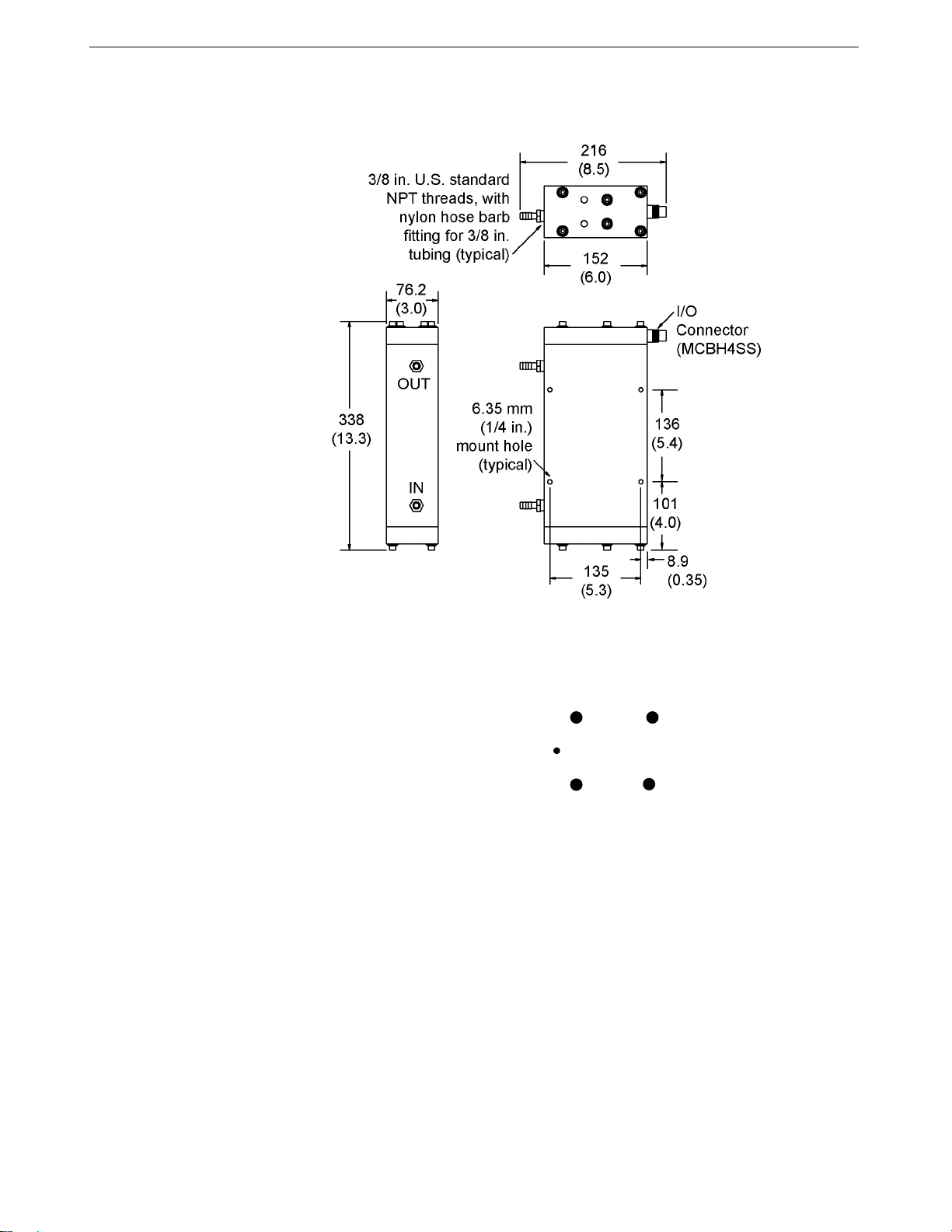
Dimensions and Connector
Dimensions in millimeters (inches)
Ground pin = Computer data common (pin 1)
Receive pin = RS-232C receive data transmitted from computer (pin 2)
Transmit pin = RS-232C transmit from MicroTSG to computer (pin 3)
Power pin = 8-30 VDC (pin 4)
Orientation Pin
Ground Pin 1
Transmit Pin 3Power Pin 4
Receive Pin 2
MCBH4SS
15

Section 2: Description of MicroTSG SBE 45
11
Sample Timing
The time to acquire the temperature and conductivity varies, depending on the
mode of operation.
Polled Sampling Mode
Polled Sampling Mode is in effect when:
•PCB J1 jumper is set to Normal or Autopower, AutoRun=N, and
sampling is started with Go (if SingleSample=Y) or with a polled
sampling command
Time from end of take sample command to beginning of reply (seconds)
= (NCycles * 0.1336) + 0.459
Autonomous Sampling Mode
Autonomous Sampling Mode is in effect when:
•PCB J1 jumper is set to Normal or Autopower, AutoRun=Y, and
SingleSample=N, or
•PCB J1 jumper is set to Normal (pins 2 and 3), AutoRun=N,
SingleSample=N, and sampling is started with Go
Time to acquire temperature and conductivity (seconds)
= (NCycles * 0.1336) + 0.287
Serial Line Sync Mode
Serial Line Sync Mode is in effect when:
•PCB J1 jumper set to Normal (pins 2 and 3), AutoRun=Y, and
SingleSample=Y
Time from wake-up to beginning of reply (seconds)
= (NCycles * 0.1336) + 1.643
Total Sampling Time
Once temperature and conductivity are acquired, the time to calculate the
desired parameters is not a function of the mode of operation:
•Time to compute temperature = 8.8 msec
•Time to compute conductivity = 15.4 msec
•Time to compute salinity = 83 msec
•Time to compute sound velocity = 35 msec
Total time required for sample =
time to acquire temperature and conductivity
+ time to compute selected parameters
+ time to transmit computed parameters
Notes:
•The time to transmit computed
parameters is dependent on baud
rate. See Baud Rate, Cable
Length, Power, and Data
Transmission Rate.
•For autonomous sampling, if the
total time required for the sample
is greater than the user-input
sample interval (Interval=), the
MicroTSG begins the next sample
as soon as it finishes transmitting
the current sample.
Note:
See Command Descriptions in
Section 4: Setting Up MicroTSG
for descriptions of AutoRun=, Go,
SingleSample=, NCycles=, and
Interval=.
16

Section 2: Description of MicroTSG SBE 45
12
Baud Rate, Cable Length, Power, and Data Transmission Rate
Baud Rate, Cable Length, and Data Transmission Rate
The rate that data can be transmitted from the MicroTSG is dependent on the
amount of data to be transmitted per scan and the serial data baud rate:
Time to transmit data =
(number of characters * 10 bits/character) / baud rate
where
Number of characters is dependent on the included data and output
format (see Data Output Format in Section 4: Setting Up MicroTSG).
Add 2 to the number of characters shown in the output format, to
account for the carriage return and line feed at the end of each scan.
Include decimal points, commas, and spaces when counting the
number of characters.
Note that the MicroTSG transmits data after it has completed the previous
sample and before it starts the next sample. See Sample Timing above for
information on sampling time.
The length of cable that the MicroTSG can drive to transmit real-time data is
also dependent on the baud rate. The allowable combinations are:
Maximum Cable Length (meters) Maximum Baud
800 1200
400 2400
200 4800 (factory set default)
100 9600
50 19200
25 38400
Notes:
•Baud rate is set with Baud=.
•Real-time output rate is set
with Interval=.
•Output format is set with
OutputCond=, OutputSal=, and
OutputSV=.
See Command Descriptions in
Section 4: Setting Up MicroTSG for
command details.
Example –
What is the minimum transmission time over 100 m of cable with OutputCond=Y, OutputSal=Y, OutputSV=Y, and
OutputFormat=0?
With 100 meters of cable, the MicroTSG requires a baud rate of 9600 or less.
Number of characters (from Data Output Format in Section 4: Setting Up MicroTSG) =
8 (T) + 2 (comma & space) + 8 (C) + 2 (comma & space) + 8 (salinity) + 2 (comma & space) + 8 (sound velocity)
+ 2 (carriage return & line feed) = 40
Time required to transmit data = (40 characters * 10 bits/character) / 9600 = 0.042 seconds = 42 msec
What is the minimum total time required per sample (Interval=), if averaging 4 measurements/sample (NCycles=4)
and operating in Autonomous Sampling Mode?
In Autonomous mode, time to acquire T and C (from Sample Timing above)
= (NCycles * 0.1336) + 0.287 = (4 * 0.1336) + 0.287 = 0.82 seconds
Total sampling time
= time to acquire T and C + time to compute parameters (from Sample Timing above) + time to transmit data
= 0.82 + (.0088 + .0154 + .083 + .035) + .042 = 1.00 second
Therefore, set Interval=1, transmitting 1 sample every second.
17
Table of contents
Other Sea-Bird Electronics Measuring Instrument manuals


