8
5. Following the vehicle manufacturer’s
recommendedprocedures,deactivate theelectrical
system in a manner that safely removes all
electrical power from the vehicle.
6. Never exceed manufacturer’s recommended
pressures.
7. Never connect or disconnect a hose or line
containing pressure; it may whip. Never remove a
component or plug unless you are certain all
system pressure has been depleted.
8. Use only genuine Bendix®replacement parts,
components and kits. Replacement hardware,
tubing, hose, fittings, etc. must be of equivalent
size, type and strength as original equipment and
be designed specifically for such applications and
systems.
9. Components with stripped threads or damaged
parts should be replaced rather than repaired. Do
not attempt repairs requiring machining or welding
unless specifically stated and approved by the
vehicle and component manufacturer.
10. Prior to returning the vehicle to service, make
certain all components and systems are restored
to their proper operating condition.
11. For vehicles with Antilock Traction Control (ATC),
the ATC function must be disabled (ATC indicator
lampshouldbe ON) prior toperformingany vehicle
maintenance where one or more wheels on a drive
axle are lifted off the ground and moving.
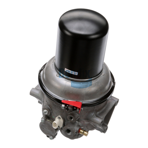
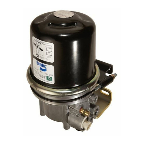
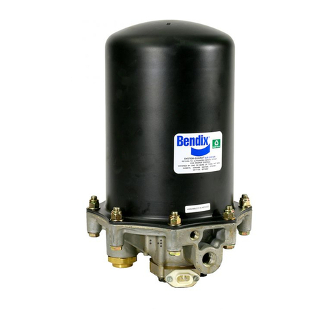
AD-9™AIR DRYER REMOVAL
1. Parkthevehicleonalevelsurfaceandpreventmovement
by means other than the brakes.
2. Drain all reservoirs to 0 p.s.i. (0 kPa).— Caution:
Compressor discharge line may still contain residual
pressure.
3. Identify and disconnect the three air lines from the end
coverandnote the positionofendcover portsrelativeto
thevehicle.
4. Unplug the vehicle wiring harness from the heater and
thermostat assembly connector on the purge valve
housingassembly.
5. Loosen the 5/16" X 4-1/2" hex cap screw (25) securing
theuppermountingstrap(26).
6. Remove, retain and mark the two 3/8" end cover cap
screws (18), lock nuts (19) and four special washers
(17) that retain the lower mounting bracket (20) to the
end cover, also mark these two holes of the end cover.
(Theseboltsare longer than the other 6 bolts.)
7. RemovetheAD-9™air dryer from itsmountingbrackets
onthevehicle.
DISASSEMBLY
The following disassembly and assembly procedure is
presented for reference purposes and presupposes that a
major rebuild of the AD-9™air dryer is being undertaken.
Severalreplacementpartsandmaintenancekitsareavailable
which do not require full disassembly. The instructions
providedwiththesepartsand kits shouldbefollowedinlieu
oftheinstructionspresentedhere.RefertoFigure7during
disassembly.
Caution: While performing service on the AD-9™air
dryer, it is not recommended that a clamping device
(vise, C-clamp, etc.) be used to hold any die cast
aluminum component as damage may result. To hold
the end cover, install a pipe nipple in the supply port
and clamp the nipple into a vise.
1. Usingan adjustablewrenchoran 1-3/4"socket,remove
the delivery check valve assembly (15) and o-ring (1).
Removetheo-ring(1)from the check valve assembly.
2. Removethethree1/4"selftappingscrews(3)thatsecure
the purge valve housing assembly to the end cover
assembly. Pullthepurgevalvehousing assembly (8)out
oftheendcoverassembly.Removetheo-rings(5,6 &7)
from the exterior of the purge valve housing assembly.
(O-ring item 6 is not included in DLU models.) Note: the
o-rings may be lodged in the end cover bores, if so, they
mustberemoved.
3. PurgeValve(8)Disassembly:
Note: Removalof thepistonfromthepurgevalvehousing
assembly requires a tool to hold the head of the purge
piston while unscrewing the purge valve shoulder bolt
(4). If an extended type exhaust cover is in use to
accommodate the attachment of an exhaust hose, the
exhaustcovermustbecarefullypeeledoffofthepurge
valve housing (9). Use a thin flat blade to pry the
exhaust cover off, taking care not to damage the
potting material (RTV sealant) under the cover. To
remove the piston (10) from the purge valve housing
assembly (9)(9) use a twelve point 1/4" socket to hold
theheadoftheshoulderbolt(4).
A. Removetheshoulderbolt(4)fromthe bottom of the
purgevalvehousingassembly(8)while securingthe
top of the purge piston (10) using the two opposing
castindentationsandatool. Removethepurgeguide
(2)andpurgevalve(11)fromthepurgevalvehousing.
B. Removethepurgepiston(10) and return spring (13)
from the opposite end of the purge valve housing.
Removethequadring(14)fromthepurgepiston(10).
C. Heater and Thermostat Assembly Replacement.
Caution: Do not attempt to remove this assembly,
as it will be damaged during the removal process
andisnot available as a service part.Iftheheater
andthermostataredefective,replacetheentirepurge
valvehousingassembly whichincludestheseitems.


