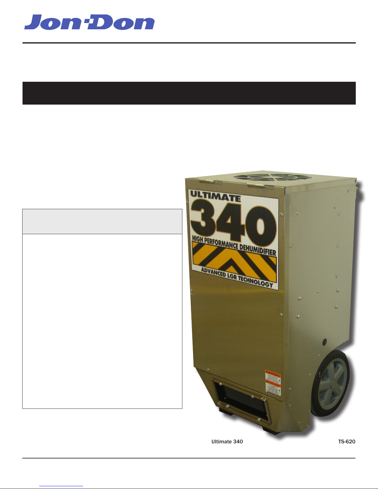
3
www.jondon.comToll-Free 1-800-556-6366
2.3 Electrical Requirements
The Ultimate 340 plugs into a common grounded outlet on a
15 Amp circuit. It draws 10 Amps at 80°F, 60% RH. If used in
a wet area, a ground fault interrupter (GFI) is required.
If an extension cord is required, it must have a minimum of
14 gauge conductors if 25 feet long or less and 12 gauge
conductors if greater than 25 feet long.
2.4 Condensate Removal
The Ultimate 340 is equipped with an internal condensate
pump to remove the water that is condensed during
dehumidication. This allows the condensate to be pumped
30’ with the attached hose. If the condensate must be
pumped more than 20 feet above the unit, a second pump
must be added to relay the condensate. If the pump fails
and the unit must be used before it can be replaced, the
condensate can be drained by gravity (see Sec. 4.9).
2.5 Ducting
A detachable rectangular exhaust collar is supplied that will
allow 10” round lay-at duct to be attached to the Ultimate
340 outlet. Lay-at plastic ducting is available from Jon-Don.
To attach ducting to a collar, put the plastic duct end through
the collar center and roll the duct end outward so that it
overlaps the outside of the collar. The duct and collar may
then be quickly attached to the Ultimate 340 by snapping the
collar over the four screws at the blower outlet.
2.6 Power Button
Press the POWER button to turn the dehumidier on or off.
When starting the dehumidier the display will show the
accumulated hours. Press the POWER button again to turn
the dehumidier off. The display will also power off.
2.7 Pump Purge Button
During normal operation the pump automatically cycles every
four minutes. Press the PURGE button to remove condensate
manually from the reservoir. There are several ways to
manually remove water from the reservoir:
1. Press the PURGE button once and the pump will run for
20 seconds
2. Press and hold the PURGE button and the pump will run
for up to 30 seconds
3. Press the PURGE button while the dehumidier is
powered off and the pump will run for 30 seconds.
Always manually purge the water reservoir before transport
or storage. Turn off the power and allow the plugged in dehu-
midier to rest 15 minutes before the nal purge.
2.8 Hour Meter
The digital hour meter displays the cumulative and job time
the dehumidier has been turned on to the tenth of an hour.
The total and job hours measured are stored when the unit is
unplugged. The previous total will be displayed the next time
the unit is turned on. The job hours can be reset by pressing
and holding the HOURS button for 5 seconds when the unit is
operating.
2.9 Humidistat
Adjust the humidistat to the desired conditioned humidity.
The humidistat has a range of 20% to 70% RH. “ON” will
operate the unit continuously regardless of humidity.
2.10 HOURS Button
Press the HOURS button when the dehumidier cannot be
plugged in and the hour meter needs to be read. The digital
hour meter will display the last saved cumulative time for ten
seconds.
2.11 DEFROST Light
The DEFROST light turns on when the unit is in defrost cycle
and indicates when the compressor is off.
DRYING TIP: Air’s ability to absorb moisture from wet
surroundings and the Ultimate 340’s ability to remove
moisture from that air is greatly improved at higher
temperatures. We recommend that the area to be dried be
heated to over 70°F if possible. Less drying time will be
required and efficiency will improve.
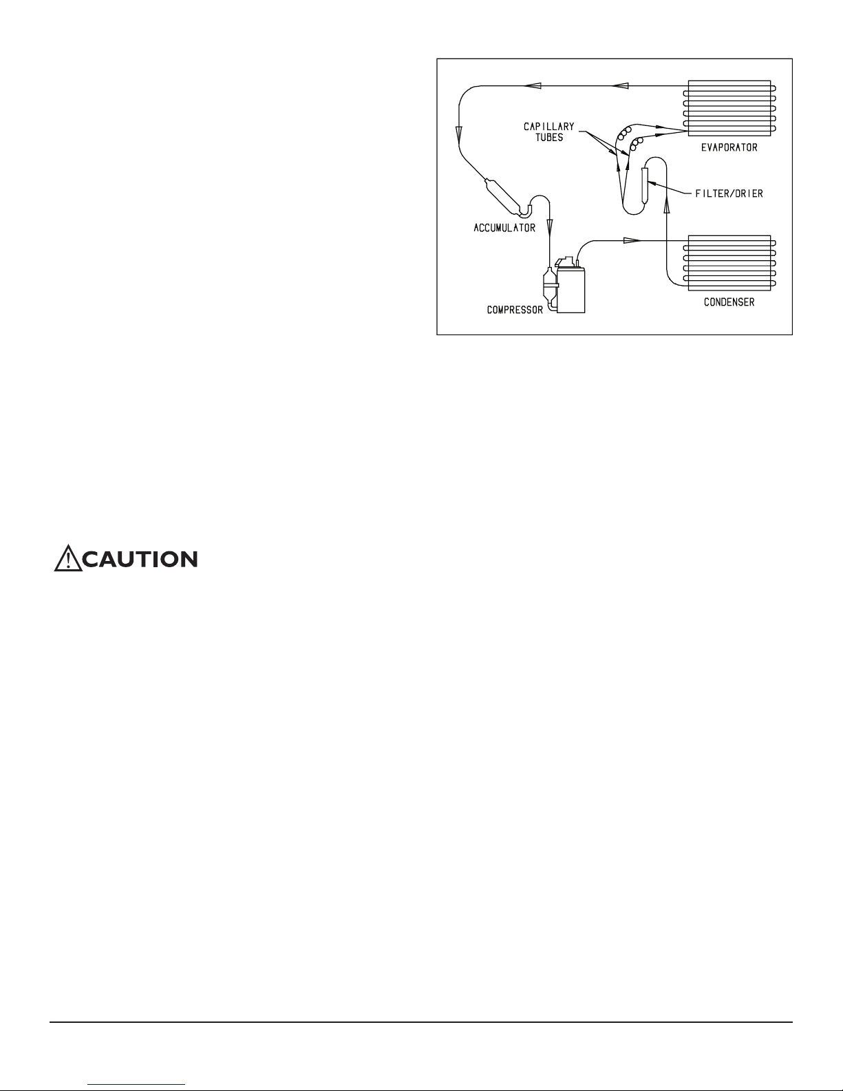
2.12 Low Pressure Control
If the low side refrigerant pressure drops to 35 PSIG, the
low pressure control opens and shuts off the compressor
and blower. It is an automatically reset control. Its primary
function is to prevent damage to the compressor if a leak
develops in the refrigeration system. It may also open if
stored where it is below 40°F and then started. Under these
conditions, the unit will restart within several minutes; it may
cycle several times until the unit warms up.
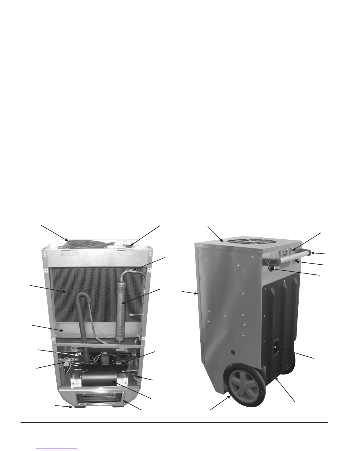
3 Maintenance
3.1 Air Filter
The Ultimate 340 is equipped with a pleated fabric air lter
that must be checked regularly. The standard lter is a MERV-
11 high efciency lter. Operating the unit with a dirty lter
will reduce the dehumidier’s capacity and efciency and
may cause the compressor to cycle off and on unnecessarily
on the defrost control.
The lter can generally be vacuumed clean several times
before needing replacement. Replacement lters can be
ordered from Jon-Don; call 1-800-556-6366 or at jondon.
com. DO NOT operate the unit without the lter or with a
less effective lter as the heat exchange coils inside the unit
could become clogged and require disassembly to clean.