BENECOM BEM-100B User manual

BEM-100B/C User’s Manual
1st Ed – 17 March 2009

BEM-100B/C
2 BEM-100B/C User’s Manual
FCC Statement
FCC STATEMENT
THIS DEVICE COMPLIES WITH PART 15 FCC RULES. OPERATION IS
SUBJECT TO THE FOLLOWING TWO CONDITIONS:
(1) THIS DEVICE MAY NOT CAUSE HARMFUL INTERFERENCE.
(2) THIS DEVICE MUST ACCEPT ANY INTERFERENCE RECEIVED INCLUDING
INTERFERENCE THAT MAY CAUSE UNDESIRED OPERATION.
THIS EQUIPMENT HAS BEEN TESTED AND FOUND TO COMPLY WITH THE LIMITS
FOR A CLASS "A" DIGITAL DEVICE, PURSUANT TO PART 15 OF THE FCC RULES.
THESE LIMITS ARE DESIGNED TO PROVIDE REASONABLE PROTECTION AGAINST
HARMFUL INTERFERENCE WHEN THE EQUIPMENT IS OPERATED IN A
COMMERCIAL ENVIRONMENT. THIS EQUIPMENT GENERATES, USES, AND CAN
RADIATE RADIO FREQUENCY ENERGY AND, IF NOT INSTATLLED AND USED IN
ACCORDANCE WITH THE INSTRUCTION MANUAL, MAY CAUSE HARMFUL
INTERFERENCE TO RADIO COMMUNICATIONS.
OPERATION OF THIS EQUIPMENT IN A RESIDENTIAL AREA IS LIKELY TO CAUSE
HARMFUL INTERFERENCE IN WHICH CASE THE USER WILL BE REQUIRED TO
CORRECT THE INTERFERENCE AT HIS OWN EXPENSE.
Notice

User’s Manual
BEM-100B/C Series User’s Manual
3
Notice:
This guide is designed for experienced users to setup the system within the shortest time.
For detailed information, please always refer to the electronic user's manual.
Copyright Notice
Copyright Notice
Copyright ©2007 Benecom co., Ltd., ALL RIGHTS RESERVED.
No part of this document may be reproduced, copied, translated, or transmitted in any form
or by any means, electronic or mechanical, for any purpose, without the prior written
permission of the original manufacturer.
Trademark Acknowledgement
Trademark Acknowledgement
Brand and product names are trademarks or registered trademarks of their respective
owners.

BEM-100B/C
4 BEM-100B/C User’s Manual
Disclaimer
Disclaimer
Benecom co., Ltd. reserves the right to make changes, without notice, to any product,
including circuits and/or software described or contained in this manual in order to improve
design and/or performance. Benecom assumes no responsibility or liability for the use of
the described product(s), conveys no license or title under any patent, copyright, or masks
work rights to these products, and makes no representations or warranties that these
products are free from patent, copyright, or mask work right infringement, unless otherwise
specified. Applications that are described in this manual are for illustration purposes only.
Benecom makes no representation or warranty that such application will be suitable for the
specified use without further testing or modification.

User’s Manual
BEM-100B/C Series User’s Manual
5
Life Support Policy
Life Support Policy
Benecom PRODUCTS ARE NOT FOR USE AS CRITICAL COMPONENTS IN LIFE
SUPPORT DEVICES OR SYSTEMS WITHOUT THE PRIOR WRITTEN APPROVAL OF
Benecom.
As used herein:
1. Life support devices or systems are devices or systems which, (a) are
intended for surgical implant into body, or (b) support or sustain life and
whose failure to perform, when properly used in accordance with instructions
for use provided in the labeling, can be reasonably expected to result in
significant injury to the user.
2. A critical component is any component of a life support device or system
whose failure to perform can be reasonably expected to cause the failure of
the life support device or system, or to affect its safety or effectiveness.
A Message to the Customer
A Message to the Customer
Benecom Customer Services
Each and every Benecom’s product is built to the most exacting specifications to ensure
reliable performance in the harsh and demanding conditions typical of industrial
environments. Whether your new Benecom device is destined for the laboratory or the
factory floor, you can be assured that your product will provide the reliability and ease of
operation for which the name Benecom has come to be known.
Your satisfaction is our primary concern. Here is a guide to Benecom’s customer services.
To ensure you get the full benefit of our services, please follow the instructions below
carefully.

BEM-100B/C
6 BEM-100B/C User’s Manual
Technical Support
We want you to get the maximum performance from your products. So if you run into
technical difficulties, we are here to help. For the most frequently asked questions, you can
easily find answers in your product documentation. These answers are normally a lot more
detailed than the ones we can give over the phone. So please consult the user’s manual
first.
To receive the latest version of the user’s manual; please visit our Web site at:
http://www.benecom.co.kr/
If you still cannot find the answer, gather all the information or questions that apply to your
problem, and with the product close at hand, call your dealer. Our dealers are well trained
and ready to give you the support you need to get the most from your Benecom’s products.
In fact, most problems reported are minor and are able to be easily solved over the phone.
In addition, free technical support is available from Benecom’s engineers every business
day. We are always ready to give advice on application requirements or specific information
on the installation and operation of any of our products. Please do not hesitate to call or
e-mail us.

User’s Manual
BEM-100B/C Series User’s Manual
7
Product Warranty
Product Warranty
Benecom warrants to you, the original purchaser, that each of its products will be free from
defects in materials and workmanship for two years from the date of purchase.
This warranty does not apply to any products which have been repaired or altered by
persons other than repair personnel authorized by Benecom, or which have been subject to
misuse, abuse, accident or improper installation. Benecom assumes no liability under the
terms of this warranty as a consequence of such events. Because of Benecom’s high
quality-control standards and rigorous testing, most of our customers never need to use our
repair service. If any of Benecom’s products is defective, it will be repaired or replaced at no
charge during the warranty period. For out-of-warranty repairs, you will be billed according
to the cost of replacement materials, service time, and freight. Please consult your dealer
for more details. If you think you have a defective product, follow these steps:
1. Collect all the information about the problem encountered. (For example, CPU type and
speed, Benecom’s products model name, hardware & BIOS revision number, other
hardware and software used, etc.) Note anything abnormal and list any on-screen
messages you get when the problem occurs.
2. Call your dealer and describe the problem. Please have your manual, product, and any
helpful information available.
3. If your product is diagnosed as defective, obtain an RMA (return material authorization)
number from your dealer. This allows us to process your good return more quickly.
4. Carefully pack the defective product, a complete Repair and Replacement Order Card
and a photocopy proof of purchase date (such as your sales receipt) in a shippable
container. A product returned without proof of the purchase date is not eligible for
warranty service.
5. Write the RMA number visibly on the outside of the package and ship it prepaid to your
dealer.

BEM-100B/C
8 BEM-100B/C User’s Manual
Contents
Notices..............................................................................................................................10
Safety information ...........................................................................................................11
About this guide ..............................................................................................................12
Typography......................................................................................................................13
BEM-100B specifications summary ...............................................................................14
1.1 Welcome!....................................................................................................................16
1.2 Package contents ......................................................................................................16
1.3 Special features .........................................................................................................17
1.3.1 Product highlights .....................................................................................................17
1.4 Before you proceed...................................................................................................19
1.5 Motherboard overview...............................................................................................20
1.5.1 Placement Direction..................................................................................................20
1.5.2 Screw Holes..............................................................................................................20
1.5.3 Motherboard Layout..................................................................................................21
1.6 System memory.........................................................................................................23
1.6.1 Overview...................................................................................................................23
1.6.2 Memory Configurations.............................................................................................23
1.6.3 Installing a DIMM......................................................................................................24
1.6.4 Removing a SO-DIMM..............................................................................................24
1.7 Expansion slots .........................................................................................................24
1.7.1 Installing an Expansion Card....................................................................................25
1.7.2 Configuring an Expansion Card................................................................................25
1.7.3 PCI slots ...................................................................................................................25
1.8 Jumpers......................................................................................................................26
1. Clear RTC RAM (CLRTC)..............................................................................................26
2. COM1 RI, +12V and +5V Power Select (JCOMPWR1, JCOMPWR2)...........................27
3. COM2 RI, +12V and +5V Power Select (JCOMPWR1, JCOMPWR2)...........................27
4. COM3 RI, +12V and +5V Power Select (JCOMPWR3, JCOMPWR4)...........................28
5. COM4 RI, +12V and +5V Power Select (JCOMPWR3, JCOMPWR4)...........................28
6. System Panel Connector (F_PANEL1)..........................................................................29
1.9 Connectors.................................................................................................................30
1.9.1 Rear panel connectors..............................................................................................30
1.9.2 Internal connectors ...................................................................................................31
1. Front panel audio connector (10-pin AAFP1).......................................................................................... 31
2. Serial Port connectors (9-pin COM3, COM4).......................................................................................... 33

User’s Manual
BEM-100B/C Series User’s Manual
9
3. CPU, Power and Chassis fan connectors (3-pin CHA_FAN).................................................................. 33
4. Digital Audio connector (4-1 pin SPDIF_OUT)........................................................................................ 34
5. USB connectors (10-1 pin USB45) ......................................................................................................... 35
6. Primary IDE connector (40-1 pin IDE1)................................................................................................... 36
7. Serial ATA connectors............................................................................................................................. 37
8. ATX power connectors (20-pin ATXPWR1)............................................................................................ 37
9. Audio Amplifier connectors (4-pin JAMP1) ............................................................................................. 38
10. SPI Connector (7-pin SPI_JP1) ............................................................................................................ 39
11. LCD Inverter Connector (5-pin JBLK)................................................................................................... 40
12. Digital IO Connector (12-pin JDIO)....................................................................................................... 40
13. LVDS Connector (40-pin JLVDS).......................................................................................................... 41
2.1 Managing and updating your BIOS .....................................................................44
2.1.1 Creating a bootable floppy disk ...........................................................................44
2.2 BIOS setup program..................................................................................................45
2.2.1 Legend Box .........................................................................................................46
2.2.2 List Box................................................................................................................46
2.2.3 Sub-menu............................................................................................................46
2.3 BIOS menu screen.....................................................................................................47
2.3.1 Standard CMOS Features...................................................................................48
2.3.2 Advanced BIOS Features....................................................................................50
2.3.3 Advanced Chipset Features ................................................................................56
2.3.4 Integrated Peripherals.........................................................................................58
2.3.5 Security Chip Configuration.................................................................................63
2.3.6 Power Management Setup..................................................................................64
2.3.7 PnP/PCI Configurations.......................................................................................66
2.3.8 PC Health Status.................................................................................................67
2.3.9 Frequency/Voltage Control..................................................................................68
2.3.10 Load Optimized Defaults .....................................................................................69
2.3.11 Set Supervisor Password ....................................................................................70
2.3.12 Set User Password..............................................................................................71
2.3.13 Save & Exit Setup................................................................................................72
2.3.14 Exit Without Saving .............................................................................................73

BEM-100B/C
10 BEM-100B/C User’s Manual
Notices
Federal Communications Commission Statement
This device complies with Part 15 of the FCC Rules. Operation is subject to the following
two conditions:
yThis device may not cause harmful interference, and
yThis device must accept any interference received including interference that may
cause undesired operation.
This equipment has been tested and found to comply with the limits for a Class B digital
device, pursuant to Part 15 of the FCC Rules. These limits are designed to provide
reasonable protection against harmful interference in a residential installation. This
equipment generates, uses and can radiate radio frequency energy and, if not installed and
used in accordance with manufacturer’s instructions, may cause harmful interference to
radio communications. However, there is no guarantee that interference will not occur in a
particular installation. If his equipment does cause harmful interference to radio or
television reception, which can be determined by turning the equipment off and on, the user
is encouraged to try to correct the interference by one or more of the following measures:
yReorient or relocate the receiving antenna.
yIncrease the separation between the equipment and receiver.
yConnect the equipment to an outlet on a circuit different from that to which the receiver
is connected.
yConsult the dealer or an experienced radio/TV technician for help.
The use of shielded cables for connection of the monitor to the
graphics card is required to assure compliance with FCC
regulations. Changes or modifications to this unit not expressly
approved by the party responsible for compliance could void the
user’s authority to operate this equipment.
Canadian Department of Communications Statement
This digital apparatus does not exceed the Class B limits for radio noise emissions from
digital apparatus set out in the Radio Interference Regulations of the Canadian Department
of Communications.
This class B digital apparatus complies with Canadian ICES-003.

User’s Manual
BEM-100B/C Series User’s Manual
11
Safety information
Electrical safety
yTo prevent electrical shock hazard, disconnect the power cable from the electrical
outlet before relocating the system.
yWhen adding or removing devices to or from the system, ensure that the power cables
for the devices are unplugged before the signal cables are connected. If possible,
disconnect all power cables from the existing system before you add a device.
yBefore connecting or removing signal cables from the motherboard, ensure that all
power cables are unplugged.
ySeek professional assistance before using an adapter or extension cord. These
devices could interrupt the grounding circuit.
yMake sure that your power supply is set to the correct voltage in your area.
yIf you are not sure about the voltage of the electrical outlet you are using, contact your
local power company.
yIf the power supply is broken, do not try to fix it by yourself. Contact a qualified service
technician or your retailer.
Operation safety
yBefore installing the motherboard and adding devices on it, carefully read all the
manuals that came with the package.
yBefore using the product, make sure all cables are correctly connected and the power
cables are not damaged. If you detect any damage, contact your dealer immediately.
yTo avoid short circuits, keep paper clips, screws, and staples away from connectors,
slots, sockets and circuitry.
yAvoid dust, humidity, and temperature extremes. Do not place the product in any area
where it may become wet.
yPlace the product on a stable surface.
yIf you encounter technical problems with the product, contact a qualified service
technician or your retailer.
The symbol of the crossed out wheeled bin indicates that the
product (electrical and electronic equipment) should not be placed
in municipal waste. Check local regulations for disposal of
electronic products.

BEM-100B/C
12 BEM-100B/C User’s Manual
About this guide
This user guide contains the information you need when installing and configuring the
motherboard.
How this guide is organized
This manual contains the following parts:
yChapter 1: Product introduction
This chapter describes the features of the motherboard and the new technology it
supports. This chapter also lists the hardware setup procedures that you have to
perform when installing system components. It includes description of the jumpers and
connectors on the motherboard.
yChapter 2: BIOS setup
This chapter tells how to change system settings through the BIOS Setup menus.
Detailed descriptions of the BIOS parameters are also provided.
Where to find more information
Refer to the following sources for additional information and for product and software
updates.
1. Benecom websites
The Benecom website provides updated information on Benecom hardware and software
products. Refer to the Benecom contact information.
2. Optional documentation
Your product package may include optional documentation, such as warranty flyers, that
may have been added by your dealer. These documents are not part of the standard
package.
Conventions used in this guide
To make sure that you perform certain tasks properly, take note of the following symbols
used throughout this manual.
DANGER/WARNING: Information to prevent injury to yourself
when trying to complete a task.
CAUTION: Information to prevent damage to the components
when trying to complete a task.
IMPORTANT: Instructions that you MUST follow to complete a
task.
NOTE: Tips and additional information to help you complete a
task.

User’s Manual
BEM-100B/C Series User’s Manual
13
Typography
Bold text Indicates a menu or an item to select
Italics Used to emphasize a word or a phrase
<Key> Keys enclosed in the less-than and greater-than sign means
that you must press the enclosed key
Example: <Enter> means that you must press the Enter or
Return key
<Key1>+<Key2>+<Key3> If you must press two or more keys simultaneously, the key
names are linked with a plus sign (+)
Example: <Ctrl>+<Alt>+<D>
Command Means that you must type the command exactly as shown,
then supply the required item or value enclosed in brackets
Example: At the DOS prompt, type the command line:
afudos /i[filename]
afudos /iP5P800VM.ROM

BEM-100B/C
14 BEM-100B/C User’s Manual
BEM-100B/C specifications summary
Specifications
System
CPU Supports Intel® FCBGA8 45nm N270 Processor
FSB 533 MHz
BIOS Award 4MB (Mega Byte) SPI BIOS
System Chipset Intel® 945GSE + ICH7-M Chipset
I/O Chipset Winbond W83627DHG-A
Memory One 200-pin SO-DIMMs up to 2GB single Channel DDR2 533 SDRAM ,
non-ECC
SSD One CompactFlash Type I/II socket
Watchdog Timer Reset: 1 sec.~255 min. and 1 sec. or 1 min./step
H/W Status Monitor Monitoring CPU temperature, voltage, and cooling fan status. Auto throttling
control when CPU overheats
Expansion Slots 1 x PCI (PCI Rev. 2.3 compliant) supports 3 PCI master
DIO 8-bit General Purpose I/O for DI and DO
S3/S4 Yes
TPM TPM1.2 (Infineon® TPM chip 9635 TT 1.2 on board)LAN (PME / RPL)
Wake up on LAN or Ring YES
Display
Chipset Intel® 945GSE GMCH integrated Graphics Media Accelerator 950
Display Memory Intel® DVMT 3.0 supports 224 MB video memory
Max Resolution CRT mode :2048x1536@75Hz , LCD mode : 2048x1536@60Hz
Dual Display BEM-100B CRT+LVDS
BEM-100C CRT+LVDS, CRT+DVI, DVI+LVDS
VGA Yes , on board GMA 950,Support for CRT resolutions up to QXGA
LVDS Support for dual-channel LVDS resolutions up to UXGA
BEM-100B Single/Dual channel 24bit LVDS
BEM-100C Single/Dual channel 18bit LVDS
LVDS Backlight power
connector Yes
Networking
LAN1 Realtek RTL8111C Gigabit LAN
LAN2 Realtek RTL8111C Gigabit LAN
Audio
Audio Codec Realtek® ALC888, 5.1 HD Audio
Audio Interface Mic in, Line in, Line out
User’s Manual
BEM-100B/C Series User’s Manual
15
Audio Amplifier (W) TPA3005D2 Stereo 6Watt
I/O Port
Back Panel I/O Port
1 x DVI port ( for BEM-100C only), 1 x PS/2 Keyboard, 1 x PS/2 Mouse, 1 x
VGA port, 2 x COM Port, 2 x RJ45 port, 4 x USB 2.0/1.1,
1 x Audio Jack (3 ports)
Internal I/O
2 x Power COM port, 1 x 2x10-pin ATX power connector, 1 x CPU fan
connector, 1 x Power fan connector, 1 x USB connectors support additional 2
USB ports, 1 x LVDS connector, 1 x LVDS inventor connector, 1 x IDE
connector, 2 x SATA connectors, 1 x Digital IO header, 1 x Front panel header,
1 x S/PDIF Out header, 1 x Audio amplifier connector, 1 x Front audio
connector, 1 x Mini-PCI Express
Mechanical & Environment
Power Type ATX mode
Operating Temp. 0 ~ 60℃(32 ~ 140℉)
Operating Humidity 0%~90% relative humidity, non-condensing
Size (L x W) 170 mm x 170 mm
* Specifications are subject to change without notice.

BEM-100B/C
16 BEM-100B/C User’s Manual
1.1 Welcome!
Thank you for buying an ® BEM-100B/C motherboard!
The motherboard delivers a host of new features and latest technologies, making it another
standout in the long line of quality motherboards!
Before you start installing the motherboard, and hardware devices on it, check the items in
your package with the list below.
1.2 Package contents
Check your motherboard package for the following items.
Before you begin installing your single board, please make sure that the following materials
have been shipped:
z1 x BEM-100B/C Mini ITX Main board
z1 x CD-ROM contains the followings:
•User’s Manual in PDF file
•Drivers
z1 x IDE cable (40-pin)
z2 x SATA cable kit (SATA and Power)
z1 x I/O Shield
If any of the above items is damaged or missing, contact your
retailer.
1
This chapter describes the
motherboard features and the
new technologies it supports.
Product
Introduction

User’s Manual
BEM-100B/C Series User’s Manual
17
1.3 Special features
1.3.1 Product highlights
The Latest Processor Technology
The Intel® N270 processor is Intel's smallest processor, built with the world's smallest
transistors and manufactured on Intel's industry-leading 45nm Hi-k Metal Gate technology.
The Intel Atom processor was purpose-built for simple, affordable, netbooks and nettops.
Intel® N270 Processor
The Intel® processor N270, implemented in 45nm technology, is power-optimized and
delivers robust performance-per-watt for cost-effective embedded solutions. Featuring
extended lifecycle support, this processor offers an excellent solution for embedded market
segments such as digital signage, interactive clients (kiosks, point-of-sale terminals), thin
clients, digital security, residential gateways, print imaging, and commercial and industrial
control. The processor remains software compatible with previous 32-bit Intel® architecture
and complementary silicon.
Intel® 945GSE Chipset
The mobile Intel® 945GSE Express Chipset provides power-efficient graphics and rich I/O
capabilities for cost-effective embedded solutions. It features an integrated 32-bit 3D
graphics engine based on Intel® Graphics Media Accelerator 950 (Intel® GMA 950)
architecture, a 533 MHz front-side bus (FSB), single-channel 400/533 MHz DDR2 system
memory (SODIMM and/or memory down), and Intel® High Definition Audio¹ interface.
The chipset consists of the Intel® 82945GSE Graphics Memory Controller Hub (GMCH)
and Intel® I/O Controller Hub 7-M (ICH7-M). It delivers outstanding system performance
and flexibility through high-bandwidth interfaces such as PCI Express,* PCI, Serial ATA,
and Hi-Speed USB 2.0 connectivity.
DDR2 memory support
The motherboard supports DDR2 memory which features data transfer rates of
1066/800/533 MHz to meet the higher bandwidth requirements of the latest 3D graphics,
multimedia, and Internet applications. The dual-channel DDR2 architecture doubles the
bandwidth of your system memory to boost system performance, eliminating bottlenecks
with peak bandwidths of up to 8.5 GB/s.
PCI Express™ interface
The motherboard fully supports PCI Express, the latest I/O interconnect technology that
speeds up the PCI bus. PCI Express features point‑to‑point serial interconnections
between devices and allows higher clockspeeds by carrying data in packets. This high

BEM-100B/C
18 BEM-100B/C User’s Manual
speed interface is software compatible with existing PCI specifications. See page 1-22 for
details.
Serial ATA technology
The motherboard supports the Serial ATA technology through the Serial ATA interfaces
and the Intel® ICH7 chipset. The SATA specification allows for thinner, more flexible cables
with lower pin count, reduced voltage requirement, and up to 300 MB/s data transfer rate.
S/PDIF digital sound ready
The motherboard supports the S/PDIF Out function through the S/PDIF interfaces at
mainboard. The S/PDIF technology turns your computer into a high-end entertainment
system with digital connectivity to powerful audio and speaker systems. See page 1-31 for
details.
Temperature, fan, and voltage monitoring
The CPU temperature is monitored by the ASIC (integrated in the Winbond Super I/O) to
prevent overheating and damage. The system fan rotations per minute (RPM) is monitored
for timely failure detection. The ASIC monitors the voltage levels to ensure stable supply of
current for critical components.

User’s Manual
BEM-100B/C Series User’s Manual
19
1.4 Before you proceed
Take note of the following precautions before you install motherboard components or
change any motherboard settings.
yUnplug the power cord from the wall socket before touching
any component.
yUse a grounded wrist strap or touch a safely grounded object
or a metal object, such as the power supply case, before
handling components to avoid damaging them due to static
electricity
yHold components by the edges to avoid touching the ICs on
them.
yWhenever you uninstall any component, place it on a
grounded antistatic pad or in the bag that came with the
component.
yBefore you install or remove any component, ensure that
the ATX power supply is switched off or the power cord is
detached from the power supply. Failure to do so may
cause severe damage to the motherboard, peripherals, and/or
components.
BEM-100B/C
20 BEM-100B/C User’s Manual
1.5 Motherboard overview
Before you install the motherboard, study the configuration of your chassis to ensure that
the motherboard fits into it.
Make sure to unplug the power cord before installing or removing
the motherboard. Failure to do so can cause you physical injury and
damage motherboard components.
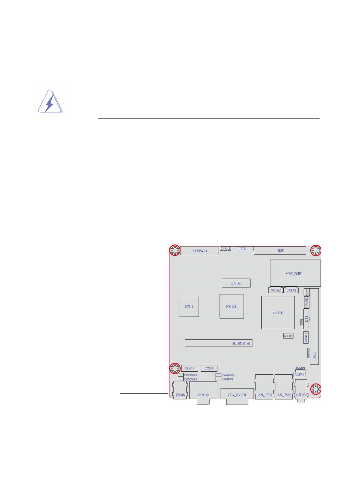
1.5.1 Placement Direction
When installing the motherboard, make sure that you place it into the chassis in the correct
orientation. The edge with external ports goes to the rear part of the chassis as indicated in
the image below.
1.5.2 Screw Holes
Place four (4) screws into the holes indicated by circles to secure the motherboard to the
chassis.
Place this side towards
the rear of the chassis
This manual suits for next models
1
Table of contents
Other BENECOM Motherboard manuals


