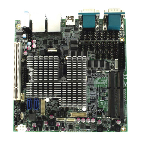
BENECOM BEM-100BYT2 User manual

Part No. E2047MXT201R
BEM-100BYT2
Intel ® Atom TM Celeron® J1900 Processor Mini ITX
Motherboard
User’s Manual
2nd Ed – 06 January 2016

BEM-100BYT2 User’s Manual
2 BEM-100BYT2 User’s Manual
FCC Statement
THIS DEVICE COMPLIES WITH PART 15 FCC RULES. OPERATION IS
SUBJECT TO THE FOLLOWING TWO CONDITIONS:
(1) THIS DEVICE MAY NOT CAUSE HARMFUL INTERFERENCE.
(2) THIS DEVICE MUST ACCEPT ANY INTERFERENCE RECEIVED INCLUDING
INTERFERENCE THAT MAY CAUSE UNDESIRED OPERATION.
THIS EQUIPMENT HAS BEEN TESTED AND FOUND TO COMPLY WITH THE LIMITS
FOR A CLASS "A" DIGITAL DEVICE, PURSUANT TO PART 15 OF THE FCC RULES.
THESE LIMITS ARE DESIGNED TO PROVIDE REASONABLE PROTECTION AGAINST
HARMFUL INTERFERENCE WHEN THE EQUIPMENT IS OPERATED IN A
COMMERCIAL ENVIRONMENT. THIS EQUIPMENT GENERATES, USES, AND CAN
RADIATE RADIO FREQUENCY ENERGY AND, IF NOT INSTALLED AND USED IN
ACCORDANCE WITH THE INSTRUCTION MANUAL, MAY CAUSE HARMFUL
INTERFERENCE TO RADIO COMMUNICATIONS.
OPERATION OF THIS EQUIPMENT IN A RESIDENTIAL AREA IS LIKELY TO CAUSE
HARMFUL INTERFERENCE IN WHICH CASE THE USER WILL BE REQUIRED TO
CORRECT THE INTERFERENCE AT HIS OWN EXPENSE.
Notice
This guide is designed for experienced users to setup the system within the shortest time.
For detailed information, please always refer to the electronic user's manual.
Copyright Notice
Copyright ©2016 Benecom Co., Ltd., ALL RIGHTS RESERVED.
No part of this document may be reproduced, copied, translated, or transmitted in any form
or by any means, electronic or mechanical, for any purpose, without the prior written
permission of the original manufacturer.
Trademark Acknowledgement
Brand and product names are trademarks or registered trademarks of their respective
owners.

User’s Manual
BEM-100BYT2 User’s Manual
3
Content
1.Getting Started............................................................................................................6
1.1Safety Precautions ....................................................................................................6
1.2Packing List...............................................................................................................6
1.3Document Amendment History ................. 오류! 책갈피가 정의되어 있지 않습니다.
1.4Manual Objectives..................................... 오류! 책갈피가 정의되어 있지 않습니다.
1.5System Specifications ...............................................................................................7
1.6Architecture Overview—Block Diagram ..................................................................10
2.Hardware Configuration...........................................................................................11
2.1Product Overview....................................................................................................12
2.2Jumper and Connector List .....................................................................................13
2.3Setting Jumpers & Connectors ...............................................................................15
2.3.1Serial port 1/2/3/4/5/6 pin9 signal select (JRI1/JRI2/JRI3/JRI4/JRI5/JRI6) ................................... 15
2.3.2SATA2/MSATA1 mPCIe slot selector (JMSW1) ............................................................................ 15
2.3.3LVDS Back Light power selection (JSBKL1).................................................................................. 16
2.3.4AT/ATX Power Mode Select (JSATX1).......................................................................................... 16
2.3.5Clear CMOS (CMOS1)................................................................................................................... 17
2.3.6LCD Inverter connector (JBKL1) .................................................................................................... 17
2.3.7Serial port 1/2 connector (COM1/2) ............................................................................................... 18
2.3.8Serial port 3/4/5/6 connector (COM3/4/5/6) ................................................................................... 18
2.3.9Serial Port 1 RS485/422 Mode connector (JRS485) ..................................................................... 19
2.3.10General purpose I/O connector (DIO1)...................................................................................... 19
2.3.11SATA Power connector 1/2 (SPWR1/2) .................................................................................... 20
2.3.12Power connector (PWR1) .......................................................................................................... 20
2.3.13USB connector 3 (USB3) ........................................................................................................... 21
2.3.14Battery connector (BT1)............................................................................................................. 21
2.3.15LVDS connector (JLVDS1) ........................................................................................................ 22
2.3.16Audio connector (FAUD1).......................................................................................................... 23
2.3.16.1Signal Description –Front Audio connector (FAUD1)............................................................ 23
2.3.17LPC connector (JLPC1) ............................................................................................................. 24
2.3.18EC_Program (EC1).................................................................................................................... 24
2.3.19PS/2 keyboard & mouse connector (KBMS1)............................................................................ 25
2.3.20BIOS connector (BIOS1)............................................................................................................ 25
2.3.21Sony/Philips Digital Interface (SPDIF1) ..................................................................................... 26
2.3.22Speaker connector (SPK1) ........................................................................................................ 26
2.3.23Miscellaneous setting connector 1 (FPT1) ................................................................................ 27
2.3.24Miscellaneous setting connector 2 (FPT2) ................................................................................ 27

BEM-100BYT2 User’s Manual
4 BEM-100BYT2 User’s Manual
2.3.25LED indicator connector 1 (LED1) ............................................................................................. 28
2.3.26LED indicator connector 2 (LED2) ............................................................................................. 28
2.3.27CPU fan connector (FAN1) ........................................................................................................ 29
3.BIOS Setup....................................................................................................................30
3.1Introduction .............................................................................................................31
3.2Starting Setup .........................................................................................................31
3.3Using Setup ............................................................................................................32
3.4Getting Help ............................................................................................................33
3.5In Case of Problems................................................................................................33
3.6BIOS setup..............................................................................................................34
3.6.1Main Menu...................................................................................................................................... 34
3.6.1.1System Language.................................................................................................................. 35
3.6.1.2System Date .......................................................................................................................... 35
3.6.1.3System Time.......................................................................................................................... 35
3.6.2Advanced Menu ............................................................................................................................. 36
3.6.2.1Trusted Computing ................................................................................................................ 36
3.6.2.2APCI Settings ........................................................................................................................ 37
3.6.2.3IT8528 Super IO Configuration.............................................................................................. 41
3.6.2.3.1Serial Port 1 Configuration .................................................................................................... 42
3.6.2.3.2Serial Port 2 Configuration .................................................................................................... 44
3.6.2.3.3Serial Port 3 Configuration .................................................................................................... 45
3.6.2.3.4Serial Port 4 Configuration .................................................................................................... 47
3.6.2.3.5Serial Port 5 Configuration .................................................................................................... 48
3.6.2.3.6Serial Port 6 Configuration .................................................................................................... 50
3.6.2.4H/W Monitor........................................................................................................................... 51
3.6.2.4.1Smart Fan Mode Configuration ............................................................................................. 53
3.6.2.5S5 RTC Wake Settings.......................................................................................................... 54
3.6.2.6Serial Port Console Redirection ............................................................................................ 56
3.6.2.6.1COM1 .................................................................................................................................... 57
3.6.2.7CPU Configuration................................................................................................................. 59
3.6.2.7.1Socket 0 CPU Information ..................................................................................................... 63
3.6.2.8PPM Configuration ................................................................................................................ 63
3.6.2.9IDE Configuration .................................................................................................................. 65
3.6.2.10LPSS & SCC Configuration ................................................................................................... 69
3.6.2.11Network Stack Configuration ................................................................................................. 73
3.6.2.12CSM Configuration ................................................................................................................ 74
3.6.2.13SDIO Configuration ............................................................................................................... 79
3.6.2.14USB Configuration................................................................................................................. 80
3.6.2.15Security Configuration ........................................................................................................... 85
3.6.2.16Lan driver report status.......................................................................................................... 87

User’s Manual
BEM-100BYT2 User’s Manual
5
3.6.3Chipset ......................................................................................................................................... 88
3.6.3.1North Bridge........................................................................................................................... 88
3.6.3.1.1Intel IGD Configuration .......................................................................................................... 89
3.6.3.1.2IGD - LCD Control ................................................................................................................. 95
3.6.3.2South Bridge .......................................................................................................................... 98
3.6.3.2.1Azalia HD Audio................................................................................................................... 101
3.6.3.2.2USB Configuration............................................................................................................... 102
3.6.3.2.3PCI Express Configuration .................................................................................................. 103
3.6.4Security....................................................................................................................................... 105
3.6.4.1Secure Boot menu ............................................................................................................. 106
3.6.4.1.1Key Management ................................................................................................................ 107
3.6.5Boot ............................................................................................................................................ 107
3.6.6Save and exit.............................................................................................................................. 108
4. Drivers Installation.....................................................................................................109
4.1Install Chipset Driver .............................................................................................110
4.2Install TXE Driver ..................................................................................................111
4.3Install VGA Driver..................................................................................................112
4.4Install Audio Driver ................................................................................................113
4.5Install Ethernet Driver............................................................................................114
4.6Install USB 3.0 Driver............................................................................................115
4.7Install MBI Driver...................................................................................................116
5. Mechanical Drawing ..................................................................................................117

BEM-100BYT2 User’s Manual
6 BEM-100BYT2 User’s Manual
1. Getting Started
1.1 Safety Precautions
Warning!
Always completely disconnect the power cord from your
chassis whenever you work with the hardware. Do not
make connections while the power is on. Sensitive
electronic components can be damaged by sudden power
surges. Only experienced electronics personnel should
open the PC chassis.
Caution!
Always ground yourself to remove any static charge before
touching the CPU card. Modern electronic devices are very
sensitive to static electric charges. As a safety precaution,
use a grounding wrist strap at all times. Place all electronic
components in a static-dissipative surface or static-shielded
bag when they are not in the chassis.
1.2 Packing List
Before you begin installing your single board, please make sure that the
following materials have been shipped:
z1 x BEM-100BYT2 motherboard
z2 x SATA cables
z1 x I/O Shield
z1 x SATA Power Cable

User’s Manual
BEM-100BYT2 User’s Manual
7
1.3 System Specifications
System
CPU Intel® Celeron® Processor J1900
(2M Cache, Up to 2.42 GHz)
BIOS AMI uEFI BIOS, 64 Mbit SPI Flash ROM
I/O Chip EC IT8528E
System Memory 2 x 204-pin DDR3L 1333MHz SODIMMs, up to 8GB
Watchdog Timer H/W Reset, 1sec. – 65535sec./min.1sec. or 1min. step
H/W Status
Monitor
CPU temperature monitoring
Voltages monitoring
CPU fan speed control
Expansion
1 x full size Mini PCI-e support mSATA (SATA II and mSATA Switchable Through
jumper)
1 x full size Mini PCI-e support WiFi module
1 x SIM card slot
1 x PCI-e x 1
1 x SD card slot support SD/ SDHC 3.0 Card
Optional Parts Optional Infineon SLB9665 support TPM 2.0
Optional eMMC 32GB
S3/S4 Yes (S0/S3/S4/S5)
Display
Resolution
HDMI: 1920x1200 @60Hz
VGA: 2560 x 1600 @ 60 Hz
2CH 18/24bits LVDS 1920 x 1080
Chrontel. CH7511B eDP to LVDS Converter
HDMI +LVDS, HDMI+VGA, VGA+LVDS
Dual Display
Ethernet
Chipset 2 x Intel I211AT PCI-Express Gigabit Ethernet
Ethernet
Interface 10/100/1000 Gigabit Ethernet
Internal I/O
Connectors
External I/O
Connector
Storage:
- 1 x full size Mini PCI-e support mSATA (SATA II and mSATA Switchable Through
jumper)
- 2 x SATA II connectors

BEM-100BYT2 User’s Manual
8 BEM-100BYT2 User’s Manual
- 2 x SATA power connectors
1 x full size Mini PCI-e support WiFi module
1 x PCI-e x 1
1 x SIM card Slot
COM:
COM1:
-COM 1 support RS- RS232/422/485 connector, with / +5V & +12V Supported and
RS422/485 by BIOS setting
1 x 2 x 5 pin, pitch 2.00mm connector for COM1: support RS-232 connector, Pin 9
with / +5V & +12V Supported
1 x 2 x 3 pin, pitch 2.00mm connector for COM1: support RS422/485 connector, Pin
5 with / +5V Supported
COM2~6:
- 5 x 2 x 5 pin, pitch 2.00mm connector for COM2~6: support RS-232 connector, Pin
9 with / +5V & +12V Supported
1 x 2 x 5 pin, pitch 2.54mm connector for 2 USB 2.0
1 x 2 x 6 pin, pitch 2.00mm connector for GPIO 8bits
1 x 2 x 4 pin, pitch 2.00mm connector for BIOS SPI
1 x 2 x 4 pin, pitch 2.00mm connector for EC SPI
1 x 2 x 5 pin, pitch 2.0mm connector for LPC
1 x horizontal type battery connector (Battery cable 170mm length)
1 x 2 x 5 pin, pitch 2.54mm connector for front panel 1
1 x 2 x 5 pin, pitch 2.54mm connector for front panel 2
1 x 2 x 20 pin, pitch 1.25mm connector for LVDS (must be using DF13-2S-1.25C
connector)
1 x 1 x 5 pin, pitch 2.00mm Wafer connector for LCD inverter backlight connector
(5V/12V)
1 x 1 x 3 pin, pitch 2.54mm connector LCD backlight brightness adjustment
(PWM/DC)
1 x 2 x 5 pin, pitch 2.54mm connector for front Audio
1 x 3 pin, pitch 2.54mm connector for S/PDIF
1 x 4 pin, pitch 2.00mm wafer connector for 3W x 2 Speaker
1 x 2 x 5 pin, pitch 2.00mm connector for Keyboard & Mouse
1 x 3 pin, pitch 2.00mm connector for CMOS clear
1 x 1 x 4 pin, pitch 2.54mm CPU fan connector with smart fan function supported
2 x 1 x 4 pin, pitch 2.00mm connector for WiFi Activity Indicator LED
1 x 2 x 2 pin, pitch 4.20mm connector for power input connector
1 x 1 x 3 pin, pitch 2.54mm connector for AT/ATX mode Fanless Operating
Rear I/O
Connectors

User’s Manual
BEM-100BYT2 User’s Manual
9
Rear Side
External I/O
Connector
2 x RJ-45
4 x USB 3.0
1 x VGA
1 x HDMI
1 x Mic-In and 1 x Line-out
1 x DC Jack lockable connector type
Mechanical &
Environmental
Power
Requirement DC in +12V
ACPI Single power ATX Support S0, S3, S4, S5
ACPI 3.0 Compliant
Power on Type AT / ATX mode Switchable Through Jumper
Operating Temp. 0 ~ 60°C (32~140°F)
Storage Temp. -40 ~ +75°C
Operating
Humidity 0%~90% relative humidity, non-condensing
Size (L x W) 6.7" x 6.7" (170mm x 170mm)
Weight 0.40 kg
If user want to install Win 8.1 Pro OS on eMMC of BEM-100BYT2 motherboard,
User must do:
A. BIOS setup menu must select eMMC mode with “PCI mode”(because selection with “ACPI mode” during
OS install, OS cannot find eMMC to install).
B. Windows OS must use Microsoft Win 8.1 Pro with update version of OS image to install.
Note: Specifications are subject to change without notice.

BEM-100BYT2 User’s Manual
10 BEM-100BYT2 User’s Manual
1.4 Architecture Overview—Block Diagram
The following block diagram shows the architecture and main components of BEM-100BYT2.

User’s Manual
BEM-100BYT2 User’s Manual
11
2. Hardware
Configuration

BEM-100BYT2 User’s Manual
12 BEM-100BYT2 User’s Manual
2.1 Product Overview

User’s Manual
BEM-100BYT2 User’s Manual
13
2.2 Jumper and Connector List
You can configure your board to match the needs of your application by setting jumpers. A
jumper is the simplest kind of electric switch.
It consists of two metal pins and a small metal clip (often protected by a plastic cover) that
slides over the pins to connect them. To “close” a jumper you connect the pins with the clip.
To “open” a jumper you remove the clip. Sometimes a jumper will have three pins, labeled 1,
2, and 3. In this case, you would connect either two pins.
The jumper settings are schematically depicted in this manual as follows:
A pair of needle-nose pliers may be helpful when working with jumpers.
Connectors on the board are linked to external devices such as hard disk drives, a
keyboard, or floppy drives. In addition, the board has a number of jumpers that allow you to
configure your system to suit your application.
If you have any doubts about the best hardware configuration for your application, contact
your local distributor or sales representative before you make any changes.
The following tables list the function of each of the board’s jumpers and connectors.
Jumpers
Label Function Note
JRI1/2/3/4/5/6 Serial port 1/2/3/4/5/6 pin9 signal select 3 x 2 header, pitch 2.00mm
JMSW1 SATA2/MSATA1 mPCIe slot selector 6 x 2 header, pitch 2.00mm
JSBKL1 LVDS Back Light power selection 3 x 1 header, pitch 2.54mm
JSATX1 AT/ATX Power Mode Select 3 x 1 header, pitch 2.54mm
CMOS1 Clear CMOS 3 x 1 header, pitch 2.00mm
Connectors
Label Function Note
FAN1 CPU fan connector 4 x 1 wafer, pitch 2.54mm
FPT1 Miscellaneous setting connector 1 5 x 2 header, pitch 2.54 mm
FPT2 Miscellaneous setting connector 2 5 x 2 header, pitch 2.54 mm
DIMM1/2 204-pin DDR3L DIMM socket
FAUD1 Front Audio connector 5 x 2 header, pitch 2.54 mm

BEM-100BYT2 User’s Manual
14 BEM-100BYT2 User’s Manual
JBKL1 LCD Inverter connector 5 x 1 wafer, pitch 2.00mm
BIOS1 BIOS connector 4 x 2 header, pitch 2.00 mm
COM1 Serial Port 1 connector 5 x 2 header, pitch 2.00mm
COM2 Serial Port 2 connector 5 x 2 header, pitch 2.00mm
COM3 Serial Port 3 connector 5 x 2 header, pitch 2.00mm
COM4 Serial Port 4 connector 5 x 2 header, pitch 2.00mm
COM5 Serial Port 5 connector 5 x 2 header, pitch 2.00mm
COM6 Serial Port 6 connector 5 x 2 header, pitch 2.00mm
DIO1 General purpose I/O connector 6 x 2 header, pitch 2.00mm
SPK1 Speaker connector 1 x 4 wafer, pitch 2.00 mm
LVDS1 LVDS Connector DIN 40-pin wafer, pitch 1.25mm
USB1/2 USB connector 1/2
USB3 USB connector 3 5 x 2 header, pitch 2.54mm
SPDIF1 Sony/Philips Digital Interface 3 x 1 header, pitch 2.54 mm
LAN1/2 RJ-45 Ethernet 1/2
PCIE1 PCIe connector
LED1 LED indicator connector 1 4 x 1 header, pitch 2.00mm
LED2 LED indicator connector 2 4 x 1 header, pitch 2.00mm
KBMS1 PS/2 keyboard & mouse connector 5 x 2 header, pitch 2.00 mm
BT1 Battery connector 2 x 1 wafer, pitch 1.25mm
MSATA1 Full size mPCIe Slot
MPCIE1 Mini-PCIe connector 1
JRS485 Serial Port 1 RS485/422 Mode
connector 3 x 2 header, pitch 2.00 mm
JLPC1 LPC connector 5 x 2 header, pitch 2.00mm
PWR1 Power connector 2 x 2 wafer, pitch 4.20mm
SATA1 Serial ATA connector 1
SATA2 Serial ATA connector 2
SPWR1/2 SATA Power connector 1/2 4 x 1 wafer, pitch 2.54mm
EC1 EC_Program 5 x 2 header, pitch 2.00 mm
DC1 DC Power-in connector
SIM1 SIM card slot
HDMI1 HDMI connector
LOUT1 Line-out audio jack
MIC1 Mic-in audio jack
VGA1 VGA connector

User’s Manual
BEM-100BYT2 User’s Manual
15
2.3 Setting Jumpers & Connectors
2.3.1 Serial port 1/2/3/4/5/6 pin9 signal select (JRI1/JRI2/JRI3/JRI4/JRI5/JRI6)
* Default
Ring*
+5V
+12V
2.3.2 SATA2/MSATA1 mPCIe slot selector (JMSW1)
* Default
Note:
SATA2/MSATA1 shared SATA signal, can not be used
simultaneously.
SATA2 Connector *
(SATA2 Connector enabled, MSATA1 slot Disabled)
MSATA1 mPCIe slot
(MSATA1 slot enabled, SATA2 Connector Disabled)
JRI
3
JRI
1
JRI4
JRI6
JRI5
JRI2

BEM-100BYT2 User’s Manual
16 BEM-100BYT2 User’s Manual
2.3.3 LVDS Back Light power selection (JSBKL1)
* Default
PWM Mode*(Max current: 2A)
DC Mode(Max current: 2A)
2.3.4 AT/ATX Power Mode Select (JSATX1)
* Default
ATX*
AT

User’s Manual
BEM-100BYT2 User’s Manual
17
2.3.5 Clear CMOS (CMOS1)
* Default
Protect*
Clear CMOS
2.3.6 LCD Inverter connector (JBKL1)
PIN Signal Max current
1 +12V 2A
2 GND
3 LVDS_BKLTEN
4 LVDS_BKLADJ
5 +5V 2A

BEM-100BYT2 User’s Manual
18 BEM-100BYT2 User’s Manual
2.3.7 Serial port 1/2 connector (COM1/2)
Signal PIN PIN Signal
NDCD # 1 2 NRXD
NTXD 3 4 NDTR#
GND 5 6 NDSR#
NRTS # 7 8 NCTS#
NRI# 9 10 NC
2.3.8 Serial port 3/4/5/6 connector (COM3/4/5/6)
Signal PIN PIN Signal
NC 10 9 NRI#
NCTS# 8 7 NRTS#
NDSR# 6 5 GND
NDTR# 4 3 NTXD
NRXD 2 1 NDCD#
COM2
COM1
COM3
COM4
COM5
COM6

User’s Manual
BEM-100BYT2 User’s Manual
19
2.3.9 Serial Port 1 RS485/422 Mode connector (JRS485)
Signal PIN PIN Signal
GND 6 5 +5V
422RX+ 4 3 485TX+
422RX- 2 1 485TX-
2.3.10 General purpose I/O connector (DIO1)
Signal PIN PIN Signal
DI0 1 2 DO0
DI1 3 4 DO1
DI2 5 6 DO2
DI3 7 8 DO3
SMB_CLK 9 10 SMB_DATA
GND 11 12 +5V

BEM-100BYT2 User’s Manual
20 BEM-100BYT2 User’s Manual
2.3.11 SATA Power connector 1/2 (SPWR1/2)
PIN Signal Max current
1 +V5S_SATA 3A
2 GND
3 GND
4 +V12S_SATA 3A
2.3.12 Power connector (PWR1)
Signal PIN PIN Signal
GND 1 2 GND
+VIN_12V 3 4 +VIN_12V
SPWR1
SPWR2
Table of contents
Other BENECOM Motherboard manuals
