Benedict K3PV-150 User manual
12 2010 Änderungen vorbehalten / Specifications are subject to change without notice D883
Betriebsvorschrift für Schütz / Operating instructions for contactor
K3PV-150, K3PV-200, K3PV-240
K3PV-150 DC1: 150A 1000V DC
K3PV-200 DC1: 200A 1000V DC
K3PV-240 DC1: 240A 1000V DC
Electric current! Danger to life!
Only skilled or instructed persons may carry out the
following operations.
Protection degree IP10 with box terminal
Achtung!
Die Montage, der Anschluß und die Inbetrieb-
nahme dieses Gerätes darf nur durch autorisierte
und fachkundige Personen erfolgen.
Schutzart IP10 mit Zusatzklemmen
Mounting
Do not operate by hand with connected power supply.
Adequate protections against short-circuits must be provided on the
supply line of the contactor.
Working position: in the vertical plane as shown in the drawings on page 2.
Installation: check that closing-opening movement is free from any
external body which may have fallen inside the contactor during
mounting and wiring operations.
Check that control voltage is correct, during operation the voltage
fluctuation must be limited in the range 0,85 to 1,1 Us.
Maintenance
Periodically check (frontally operating) the contacts wear.
After a short circuit check the contact conditions. Shout there be
some contact tip welded, disjoin them by a screwdriver.
Contact welding occurs with high current conditions, investigate the
cause of contact welding.
Montage
Händische Betätigung des Schützes bei angeschlossener Spannungs-
versorgung ist verboten!
Schütz nur mit entsprechendem Kurzschlußschutz auf der Netzseite
(Sicherung oder Leistungsschalter) betreiben.
Zulässige Einbaulage siehe Maßzeichnung Seite 2.
Bei Montage und Verdrahtung des Schützes ist darauf zu achten, dass
keine Teile in den Schütz hineinfallen und die Funktion des Schützes
behindern.
Es ist zu überprüfen dass die Steuerspannnung mit der Nennspannung
der Spule (Spulenspannugsbereich 85-110%) übereinstimmt.
Wartung
Die Kontaktabnützung ist periodisch zu überprüfen.
Nach einem Kurzschluß sind die Kontakte zu überprüfen. Leichte
Verschweißspuren sind mit einem Schraubenzieher zu entfernen.
Kontaktverschweißung entsteht durch hohe Ströme. Die Ursache
ist zu eergründen und zu beseitigen.
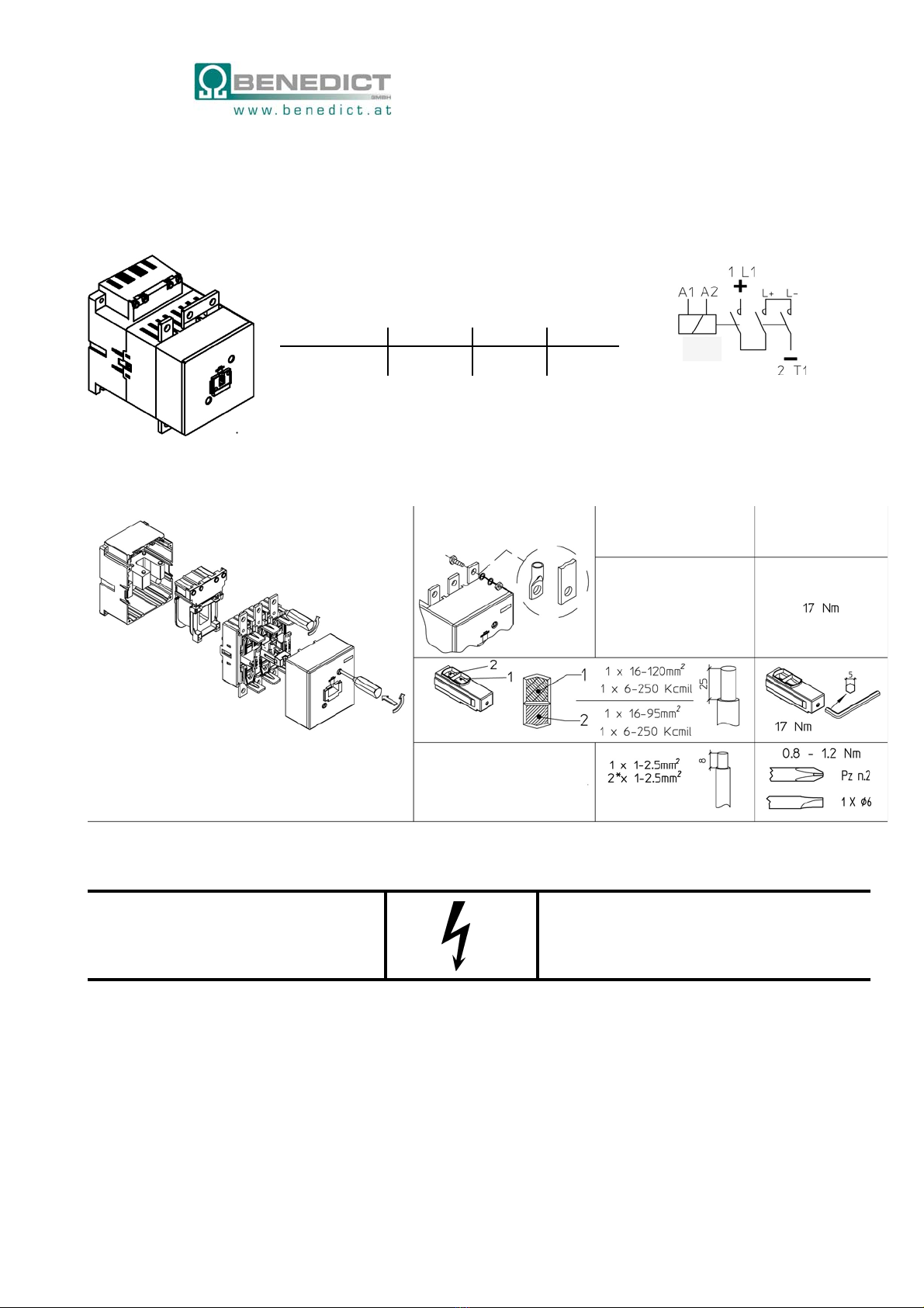
Schaltbild / Switch diagram
Hauptanschlüsse mehr-oderfeindrähtig Drehmoment
Maincircuitconnections flexibleorstranded Tighteningtorque
max.120mm²
Schienenbreitemax.20mm
SchraubeM8x 25
max.120mm²
busbarwidthmax.20mm
screwsize M8 x 25
mitZusatzklemmen
withbox terminal
Hilfsanschlüsse
Aux.circuitconnections
* 2 gleiche Leiter
* 2 cables with same section
Kurzschlußschutz / Short circuit protection
Coordination type K3PV-150 K3PV-200 K3PV-250
1 gR 160A 200A 250A
Sicherung Hilfskontakte 10A gG/gL
Fuse: Aux. contacts 10A gG/gL
Spulenleistung / Coil consumption Anzug / Inrush Halten / Sealed
wechselstrombetätigt / ac-operated 350 VA 5 VA
gleichstrombetätigt / dc-operated 350 W 5 W
Spulentausch
Coil replacement
Lieblgasse 7, A-1220 Wien
Tel.: +43 (0) 1 251 51- 0
Fax: +43 (0) 1 251 51-89
e-mail: [email protected]
www.benedict.at

12 2010 Änderungen vorbehalten / Specifications are subject to change without notice D883
Montage Zubehör / Mounting Accessories
Montage mit 4 Schrauben M5
Lock by 4 screws M5
HKT..
HKA. HKA.
HKT11
HKT22
Maße / Dimensions
HKA.
Mechanische Verriegelung
Mechanical Interlock
Bei 2-poliger Schaltung Verbindung L+ - L- entfernen
For using as two-poles contactor remove the connection L+ - L-
Anschlußschema / Connection diagrams
This manual suits for next models
2
Table of contents


