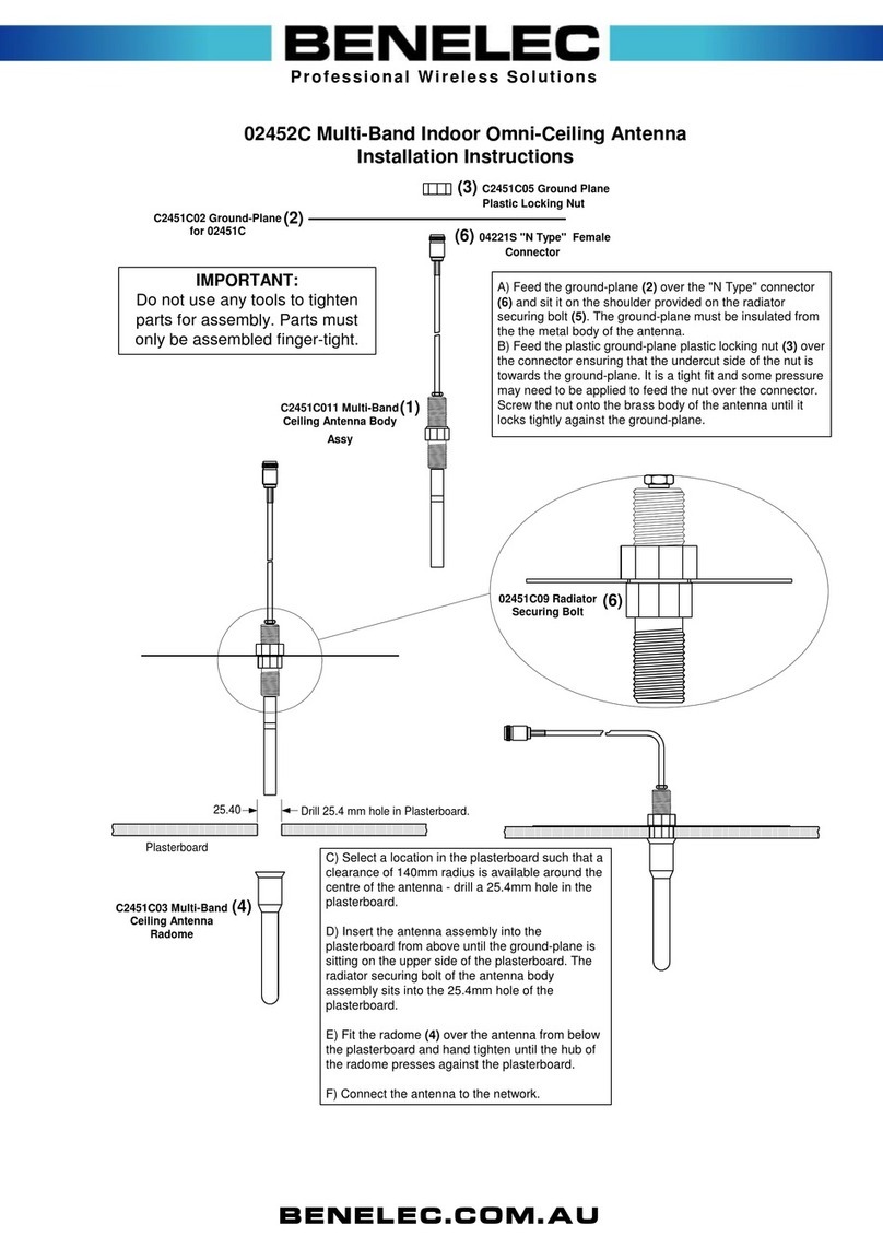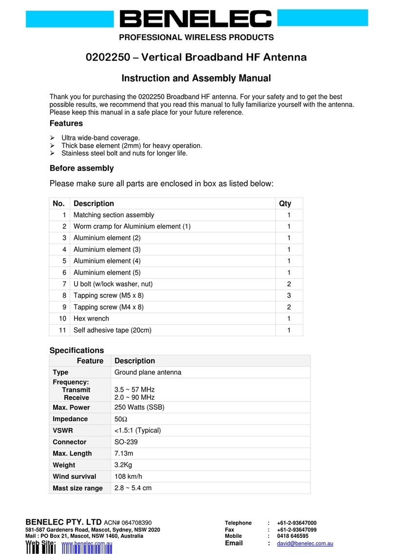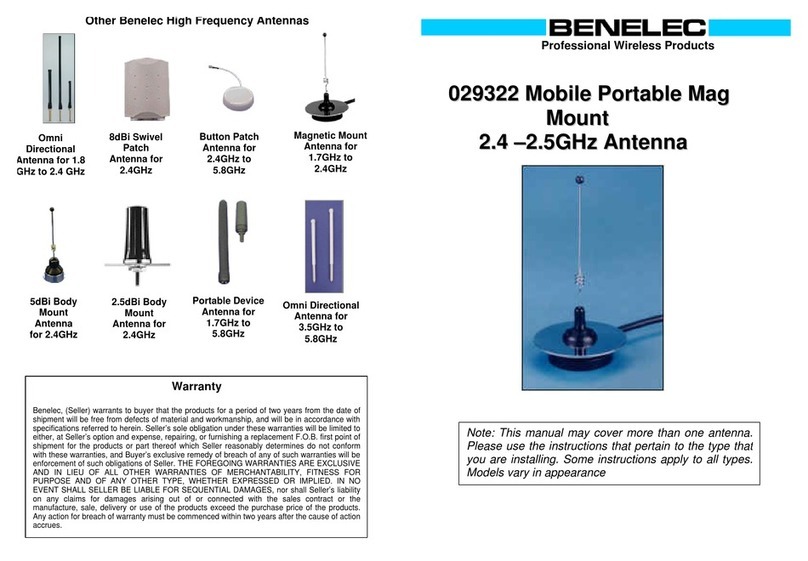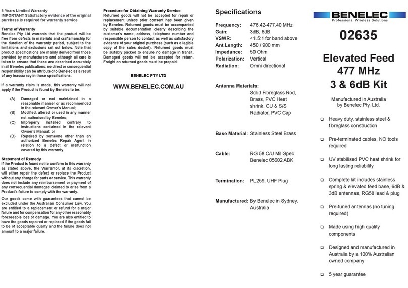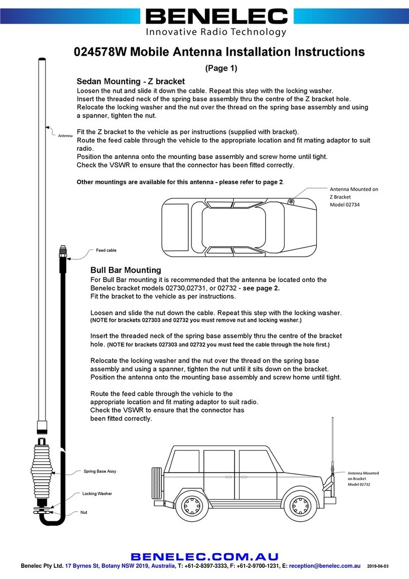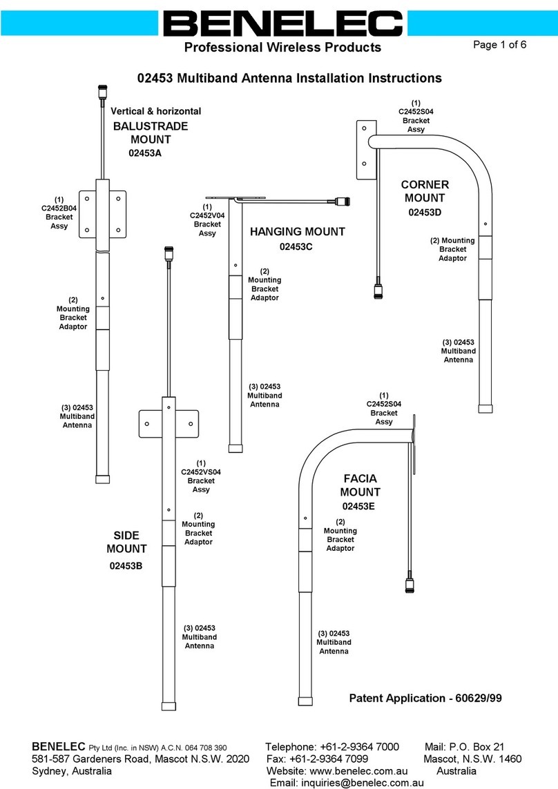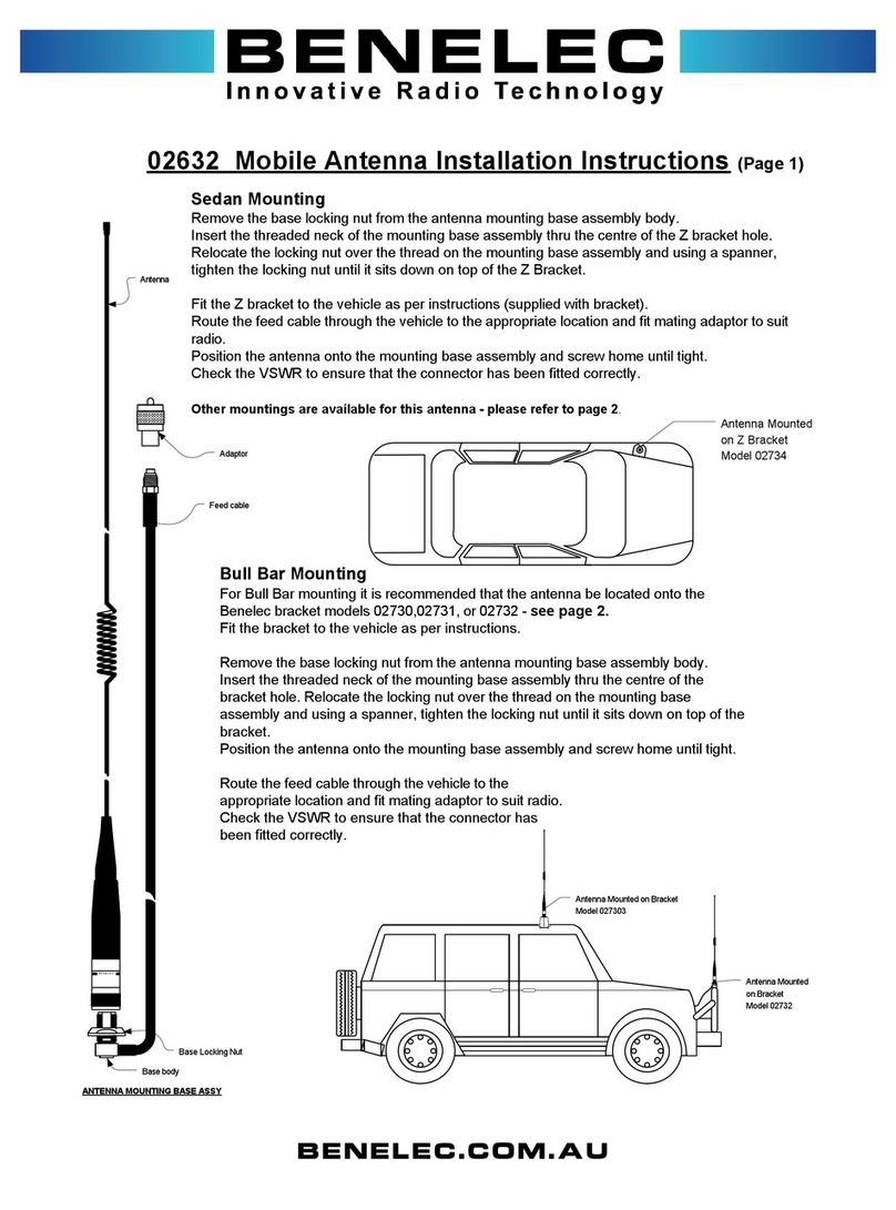
It is important that the antenna is correctly earthed, via the earth stake, or to a
vehicle body. When attaching the counterpoise to a vehicle ensure the earth clip
has good contact with a bare metal part of the vehicle chassis or body. Painted,
rusted or greasy surfaces will not allow a good earth. When using the earth stake
try to insert it into the ground as far as possible. Fully extend the counterpoise
wire. In dry conditions, wetting the soil where the earth stake is inserted will give
much better earthing.
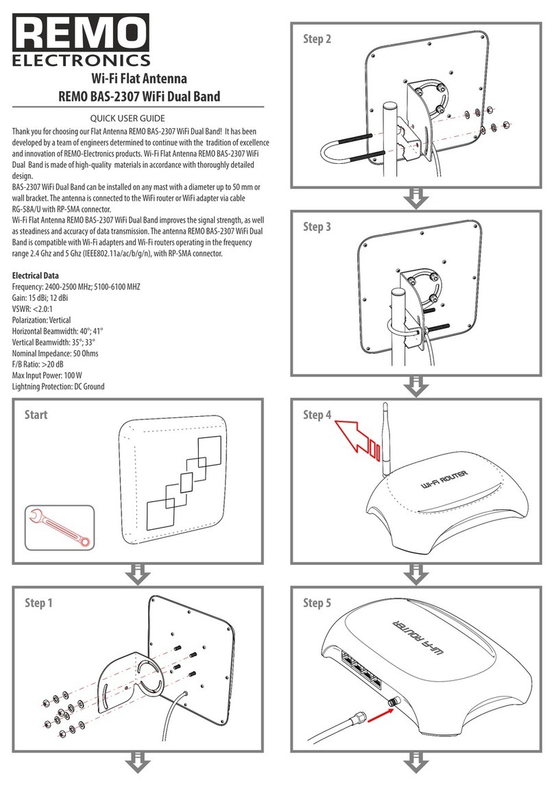
When no trees or other tall support structures are available the antenna should
be suspended as high as possible using whatever means available. The general
rule is, the higher the radiating portion of the antenna, the better the performance.
Bushes, roadside signs, or fence posts can be used. If suspending from a wire
fence ensure antenna is at a right angle to the fence line. The antenna will work,
stretched out on the ground, but performance will be reduced.
Professional Wireless Solutions
Operating the HF Dipole Wire Antenna
Method 1 (Earth stake and counterpoise)
Method 2 (Earthing the antenna with a vehicle)
MADE IN
AUSTRALIA
Radiating portion of antenna
Method 2
Metal load
cylinder
Alternatively
transceiver may be
mounted in vehicle
Transceiver
Short cord (supplied)
Earth clip connected to tow bar
or other metal part
Method 1
Tree or other support
This method is used when it is inconvenient to earth the
antenna to a vehicle or no vehicle is available.
This method is used if a vehicle mounted transceiver is being
used or if a vehicle is available and can be placed conveniently
in the erection location. All other factors being equal it will gen-
erally give better results.
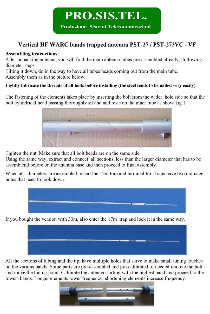
1) Select location. A large tree or other support in a clear area is best.
Avoid areas with large numbers of trees around the antenna, if possible,
as this will reduce performance. Selecting the highest point of ground,
if suitable, will enhance performance. If possible arrange antenna so that
the earthed or low end of the antenna points in the general direction of the
station you most desire to contact. (see diagram)
2) Un-reel the antenna in the preferred direction, in a straight line along
the ground. Tie the bare end of the long throw cord securely to the white,
eyelet located near the small metal cylinder. Erect the antenna using
the throw cord. When throwing the weight over a tree limb try to select a
smooth clear branch away from other branches, to facilitate retrieval of
the cord later.
3) The end of the antenna (load wire) will drop vertically from the suspen-
sion point. Allow it to drape along the ground. Do not prevent tail of load
wire from contacting ground.
2) Attach the clip at the end of the counterpoise to the tow bar or other
point on chassis or body where a bare metal contact can be made. The
counterpoise wire can lay loosely on the earth and does not need to be
tight.
3) Connect your transceiver to the balun box with supplied coax.
1) Follow through instructions for method 1. to include step 3. Place
vehicle in position (refer diagram) Tie short throw cord to white
eyelet near balun box and secure other end to the vehicle as high as
possible. (a roof rack is ideal, otherwise to highest convenient point.)
The antenna should be fully extended and tight.
4) Place the earth stake through the metal ring located near the balun box,
and push it fully into the ground. The antenna should be fully extended
and pulled tight. Extend the counterpoise wire fully in direction shown on
diagram.
5) Connect your transceiver to the balun box using the coaxial cable
provided.
Balun box
Earth stake
Counterpoise
(extended fully)
Allow load wire to
drape along ground
Loop in earth wire
near balun box
Coax: to trans-
ceiver
Best communication occurs
this direction
White eyelet
Load Wire
Throw
Cord
Earthing
Emergency Use
Unreeling & reeling the antenna
1) Unfold the black handle.
2) Insert the earth stake through the metal saddles on the shuttle body.
The earth stake then becomes the axle on which the antenna is unwound
3) Holding the earth stake in one hand wind or unwind the antenna with
the black handle.
When rewinding the antenna do not over tighten the cable or allow it to
become kinked.
Fold out handle
Insert earth stake
through saddles on
shuttle body
Hold earth stake
in one hand, wind/
unwind with other
NCAGE: Z4712
