MAHA MBT 2200 LON User manual

Fehler! Verwenden Sie die Registerkarte 'Start', um Name dem Text zuzuweisen, der hier angezeigt werden soll.Fehler! Verwenden Sie
die Registerkarte 'Start', um Name dem Text zuzuweisen, der hier angezeigt werden soll.Fehler! Verwenden Sie die Registerkarte
'Start', um Name dem Text zuzuweisen, der hier angezeigt werden soll.
MBT LON
Roller Brake Tester
Original Operating Instructions
BA022301-en
Pos: 1 / Te chnisc he D okum entat ion/A lle G erä te/Tit eltex te/Tit eltext : M BT LON - Alle Type n @ 30\m od_1352879906587_0.docx @ 1676381 @ @ 1
MBT 2200 LON
MBT 2400 LON 4WD
MBT 3200 LON
MBT 3400 LON 4WD
MBT 4200 LON COMPETENCE/CLASSIC
MBT 4400 LON 4WD
MBT 5200 LON W COMPETENCE/CLASSIC
MBT 6200 LON W CLASSIC
MBT 7200 LON W COMPETENCE/CLASSIC
MBT 7400 LON 4WD
Pos: 2 / -----F or m at---- -/MAN UEL LE R UM B RUCH Seite num br uc h @ 0\m od _ 113 44 035 77 687_ 0.d ocx @ 1277 @ @ 1

2
BA022301-en
Pos: 3 / -----F or m at---- -/In ha ltsv er z eic hn is - 3 Eb e ne n @ 5\m od_ 11 6 8867 4 410 46_ 7 5.d ocx @ 72920 @ @ 1
Contents
1Safety ......................................................................................................................5
1.1 Introduction......................................................................................................................................... 5
1.2 Symbols .............................................................................................................................................. 5
1.3 Intended Use....................................................................................................................................... 5
1.4 Inappropriate Use................................................................................................................................ 5
1.5 Requirements on Operating and Service Personnel............................................................................. 5
1.6 Safety Instructions for Installation and Initial Operation ........................................................................ 6
1.7 Safety Instructions for Operation ......................................................................................................... 6
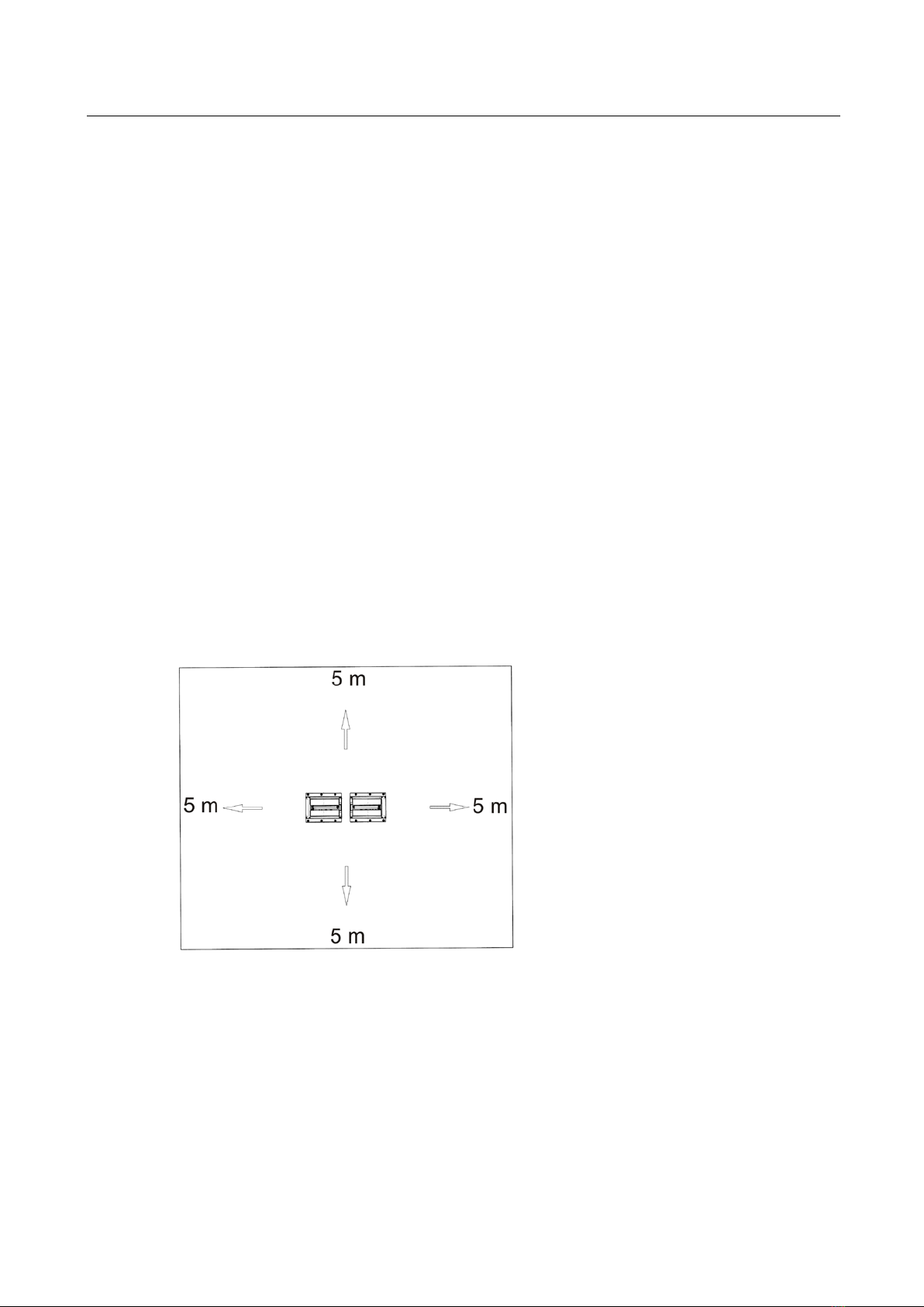
1.8 Danger Zone ....................................................................................................................................... 7
1.9 Safety Instructions for Servicing........................................................................................................... 7
1.10 Safety Features ................................................................................................................................... 8
1.11 Accessories......................................................................................................................................... 9
1.12 What to Do in the Event of an Accident............................................................................................... 9
2Description.............................................................................................................10
2.1 General Information ........................................................................................................................... 10
2.2 Noise Emission.................................................................................................................................. 10
2.3 Specifications .................................................................................................................................... 11
3Transport and Storage ...........................................................................................18
4Installation and Initial Operation ..............................................................................18
5Operation...............................................................................................................18
5.1 Main Switch....................................................................................................................................... 18
5.2 Analog Displays................................................................................................................................. 19
5.3 Remote Control................................................................................................................................. 24
5.4 Menu Structure ................................................................................................................................. 27
5.5 Car Brake Tester with MAH-DOT and IFB ......................................................................................... 30
5.6 Car Brake Tester with MAH-DOT and RECO 1.................................................................................. 31
5.7 Truck Brake Tester with MAH-DOT and FFB..................................................................................... 33
5.8 Truck Brake Tester with MAH-DOT and RECO 1 .............................................................................. 35
5.9 Option Drive Control.......................................................................................................................... 36
5.10 Noise Detection with IFB / FFB / RECO 1.......................................................................................... 38
5.11 MSD 3000......................................................................................................................................... 40
5.12 Clock Changing between Daylight Saving Time/Standard Time......................................................... 42
5.13 Test Procedure with Software ........................................................................................................... 43
6Maintenance ..........................................................................................................46
6.1 Annual Inspection.............................................................................................................................. 46
6.2 Care Instructions ............................................................................................................................... 46
6.3 Spare Parts ....................................................................................................................................... 46
6.4 Chain Drive Maintenance: Cleaning, Retensioning, Lubricating.......................................................... 47
6.5 Greasing the Sensor Roller Hinges .................................................................................................... 51

3
BA022301-en
6.6 Troubleshooting ................................................................................................................................ 52
7Dismantling ............................................................................................................55
8Disposal.................................................................................................................55
9Contents of the Declaration of Conformity ..............................................................56
10 Company Information.............................................................................................57
Pos: 4 / -----F or m at---- -/MANUELLERUM B RUCH Seite num b ruc h @ 0\mod _ 11 344 03 577 6 87_ 0.d ocx @ 1 27 7 @ @ 1

4
BA022301-en
Pos: 5 / -----F or m at---- -/MAN UEL LE R UM B RUCH Seite num br uc h @ 0\m od _ 113 44 035 77 687_ 0.d ocx @ 1277 @ @ 1

5
BA022301-en
Pos: 6 / Te chnisc he D okum entat ion/A lle G erä te/Üb erschr ifte n/Übers chr iften 1/ S/Übers chrift 1: Sich erheit @ 6\mod_1174482399906_75.docx @ 76962@ 1 @ 1
1
Safety
Pos: 7 / Te chn isc he Dokum en tat i on/A ll e Ger ä te/ Über schr if te n/ Über sc hr ift en 1.1/E/ Über s c hrif t 1.1: E inf ühru ng @ 6\m od_1174482219062_75.docx@ 76793 @ 2 @ 1
1.1
Introduction
Pos: 8 / Te chn isc he Dokum en tat i on/A ll e Ger ä te/I n hal te/S ic her he it/I n ha lt: E inf ühr u ng Sicher hei t_ 12p t @ 2 5\mod_1324455248318_75.docx @ 1138886@ @ 1
Thoroughly read this manual before operating the equipment and comply with the
instructions. Always display the manual in a conspicuous location.
Personal injury and property damage incurred due to non-compliance with these
safety instructions are not covered by the product liability regulations.
Pos: 9 / Te chnisc he D okum entat ion/A lle G erä te/Üb erschr ifte n/Übers chr iften 1.1/ S/ Üb er sc hr if t 1. 1: Sym b o le @ 6\mod_1174482270875_75.docx @ 76865@ 2 @ 1
1.2
Symbols
Pos: 10 /Techn ische Dokume ntation/Al le Geräte/Inh alte/Sicher heit/Inhal t: Symbole Sicher heit_12pt @ 2 5\mod_1324456650897_75.docx@ 1139046@ @ 1
Important safety instructions. Failure to comply with instructions could result in
personal injury or property damage.
Important information.
Pos: 1 1 / Techn ische Dokume ntat ion/Al le G eräte/ Übers chr iften/ Übers chrifte n 1. 1/B/ Übers chrift 1.1: Bes timm ungsg emäßer Gebr auch @ 6\m od_117 6734 02220 3_75.d ocx @ 8 8746 @ 2 @ 1
1.3
Intended Use
Pos: 1 2 / Tec hn isch e Dokume nt at io n/Br ems pr üft ec hn ik/ - Ar c hiv -/- Bremspr üf tec hnik A lle -/ In halte/S ic herh ei t/Inha lt: Bestimmu ngs gem äßer Gebr auch BPS_1 2pt @ 26\mod_1326368132160_75.docx@ 1504745@ @ 1
This equipment is to be used exclusively for the brake testing of motor vehicles.
Observe the rated axle load.
The equipment shall not be modified without the express written consent of the
manufacturer. In case of non-compliance the declaration of conformity becomes
void.
Pos: 1 3 / Techn ische Dokume ntat ion/Al le G eräte/ Übers chr iften/ Übers chrifte n 1. 1/B/ Übers chrift 1.1: Bes timm ungsw idr iger Geb rauc h @ 18\m od_1255530265027_75.docx@ 471571 @ 2@ 1
1.4
Inappropriate Use
Pos: 1 4 / Techn ische Dokume ntat ion/Al le G eräte/ Inh alte/Si cher heit/In halt: Bestimm ungsw idr iger G ebrau ch al lg_1 2pt @ 25\mod_1324455015938_75.docx @ 1138843 @ @ 1
Any use other than described is inappropriate.
Pos: 1 5 / Techn ische Dokume ntat ion/Al le G eräte/ Übers chr iften/ Übers chrifte n 1. 1/A/Üb ersc hrif t 1. 1: Anf ord erun gen a n d as Bed ien ungs- und S erviceper sonal @ 34\mod_1380637497630_75.docx @ 1835413@ 2 @ 1
1.5
Requirements on Operating and Service Personnel
Pos: 16 /Techn ische Dokument ation/Alle Ger äte/Inh alte/ Si ch er he it/I nha lt: Anfor de run ge n a n das Be die nu ngs- u nd Servicep ersona l_12pt (20 16-12-22 08: 48: 1 2) @ 34\m od_1 38063 73483 20_ 75.docx @ 1 83536 9 @ @ 1
All persons employed in the operation, maintenance, installation, removal and dis-
posal of the device must
•be at least 18 years old,
•be trained and instructed in writing,
•have read and understood this manual
•be on record as having been instructed in safety guidelines.
Pos: 1 7 /----- Form a t-----/ MA N UE L LE R UM BR UC H S e i ten um b r uch @ 0\mod_1134403577687_0.docx@ 12 77 @ @ 1

6
BA022301-en
Pos: 1 8 / Techn ische Dokume ntat ion/Al le G eräte/ Übers chr iften/ Übers chrifte n 1. 1/S/Üb ersc hrif t 1. 1: Sic herhe itsv orschr iften f ür Ins ta llati o n und Ers tinb e trieb n ahm e @ 24\m od_1 31056 50594 31_75. docx @ 1 02354 3 @ 2 @ 1
1.6
Safety Instructions for Installation and Initial Operation
Pos: 1 9 / Tec hn isch e Dokume nt at io n/Br ems pr üft ec hn ik/ - Ar c hiv -/- Bremspr üf tec hnik A lle -/ In ha lte/S iche rh ei t/I nha lt : S ic her he itsv ors chr ifte n f ür die I nbe tr iebn ahm e BPS_ 12p t @ 2 6\mod_1326368324234_75.docx @ 1504789@ @ 1
•The system shall only be commissioned by MAHA service technicians or au-
thorized service partners.
•All parts of the electrical equipment must be protected from moisture and wet-
ness.
•The system shall not be installed and operated in hazardous locations or wash
halls.
•The operator must provide for optional safeguards (e.g. warn lamps, barriers,
etc.) depending on local conditions.
•Wear safety shoes and gloves.
•Safeguard roller set with suitable means (e.g. cordon chains or strap).
•The display must be installed in a secure area and folded into the wall when not
in use (wall hinges optionally available).
•When folding the display, grasp it on the edges. Danger of pinching!
•Ensure that a lockable emergency-stop main switch is installed based on instal-
lation instructions before connecting the feed line. Use motor protection switch
and cable cross sections as per specification. Reference in circuit diagram
(standard delivery), nameplate. Fuse max. X.X A (see nameplate).
•The main switch must be provided by the customer and installed on-site. It
must be positioned in direct vicinity to the tester and takes over the emergency-
stop function.
Pos: 2 0 / Techn ische Dokume ntat ion/Al le G eräte/ Übers chr iften/ Übers chrifte n 1. 1/S/Üb ersc hrif t 1. 1: Sic herhe itsv orschr iften f ür den Betri eb @ 6\mod_1174482268953_75.docx @ 76826@ 2 @ 1
1.7
Safety Instructions for Operation
Pos: 2 1 / Tec hn isch e Dokume nt at io n/Br ems pr üft ec hn ik/ - Ar c hiv -/- Bremspr üf tec hnik A lle -/ In ha lte/S iche rh ei t/I nha lt : S ic her he itsv ors chr ifte n f ür den B etr i eb BPS_12pt@ 26\mod_1326700788796_75.docx @ 1505493@ @1
•The system shall only be operated within its performance limits.
•The system shall only be operated by trained personnel.
•The system and surrounding area must be kept clean.
•Switch off the system when not in use and secure the main switch against re-
start with a padlock.
•In emergency situations switch off system with main switch or emergency-stop
switch.
•No persons shall be in the danger zone of the system. Rotating or moving parts
(e.g. test stand rollers) are dangerous.
•Danger of carbon monoxide poisoning with running vehicle engine in closed
rooms. The operator is responsible for providing sufficient air exchange.
•Avoid unnecessary strain on vehicle and tester.
•Drive the vehicle slowly on to the tester.
•Check the danger zone before driving the vehicle onto the tester.

7
BA022301-en
•When the vehicle with the driven axle is on the roller set, exit only with running
roller drive. Exiting with roller drive at standstill can destroy the motors due to
extreme roller acceleration.
•The system shall not be operated without functioning slip monitoring. This can
cause tire damage.
•Never jump start a vehicle with the system. This can lead to equipment dam-
age.
•No 4 wheel-drive vehicles shall be tested on the standard roller set. Damage to
vehicle and system are possible. When in doubt contact your responsible ser-
vice representative.
•The vehicle must be closed during testing. If persons outside of the vehicle are
endangered, use noise protection.
•The operator shall not leave the vehicle during testing.
•No vehicle shall be parked in/on the roller set or on the optional ramps.
Pos: 2 2 / Techn ische Dokume ntat ion/Al le G eräte/ Übers chr iften/ Übers chri fte n 1.1/G/ Über sc hr if t 1.1: G e fa hre nzo ne @ 1 9\m od_12 6693 81226 76_75.d ocx @ 78 2826 @ 2 @ 1
1.8
Danger Zone
Pos: 2 3 / Tec hn isch e Dokume nt at io n/Br ems pr üft ec hn ik/ - Ar c hiv -/- Bremspr üf tec hnik A lle -/ In ha lte/S iche rh ei t/I nha lt : G efa hr enzo ne - 5m Ab st and (Te x t) BPS_ 12p t @ 26\m od_1326700917541_75.docx@ 1505537@ @ 1
During brake tester operation no persons are allowed in the danger zone:
5 (five) meters
around the roller set in all directions.
Pos: 2 4 / Tec hn isch e Dokume nt at io n/Br ems pr üft ec hn ik/ - Ar c hiv -/- Bremspr üf tec hnik A lle -/ In ha lte/S iche rh ei t/I nha lt : G efa hr enzo ne - 5m Abst and ( Bild) BPS @ 19\mod_ 12 66 938 2 60 034_ 0.d ocx @ 7 84 01 7 @ @ 1
Pos: 25 /Techn ische Dokument ation/Alle Ger äte/Übers chriften/ Überschri ften 1.1/S/Über schrift 1. 1:S icherheit svorschr iftenf ür Servicearb eiten @ 6\mod_1174482270640_75.docx @ 76850@ 2 @ 1
1.9
Safety Instructions for Servicing
Pos: 2 6 / Tec hn isch e Dokume nt at io n/Br ems pr üft ec hn ik/ - Ar c hiv -/- Bremsprüftec hn ik A ll e -/I n ha lte/S ic her h eit/ Inha lt : S ic her he itsv or schr i fte n f ür S erv i cear be ite n BPS_1 2p t @ 26\mod_1326700977270_75.docx @ 1505581@ @1
•Service work shall only be done by MAHA service technicians or authorized
service partners.
•Work on electric parts of the system shall only be done by trained electricians.
•The main switch must be switched off and secured against restart before doing
repair, maintenance and set-up work.
•Fire danger due to rubber abrasion on the roller set. Clean regularly. Remove
abrasion before maintenance work.

8
BA022301-en
•The main switch must be secured and if necessary the motor protection switch
turned off when doing work in the roller set.
•When working on the control cabinet or on the roller sets pay attention to the
heating (optional) or hot parts.
•Immediately turn off the tester when it starts up unintentionally. Contact the ser-
vice department.
Pos: 2 7 / Tec hn isch e Dokume nt at io n/Al le Gerät e/ Über sc hr ift en/ Üb er schr if te n 1. 1/ S/Üb er sc hr if t 1. 1: S ic her he its einr ic ht un gen @ 6\mod_1174483324765_75.docx @ 77 103 @ 2 @ 1
1.10
Safety Features
Pos: 2 8 / Tec hn isch e Dokume nt at io n/Br ems pr üft ec hn ik/ - Ar c hiv -/- Bremspr üf tec hnik A lle -/ In ha lte/S iche rh ei t/I nha lt : S ic her he its ei nr ic htun ge n ( Tex t) BPS_1 2pt @ 26\mod_1326701513692_75.docx@ 1505625@ @ 1
The safety features (partly optional) are to be inspected regularly by an authorized
service technician. Official guidelines must be followed at all times.
The equipment
shall not be operated when the safety features are defective!
•
Lockable Main Switch
Serves as normal On and Off switch for the equipment and as emergency switch.
The switch can be padlocked to protect it against unauthorized usage.
•
Emergency Switch
Is used for quick switch-off during operation. Interrupts the power supply to the
equipment.
•
Startup Monitoring
Prevents the rollers from starting up in case the wheels are blocked (seized
bearings, jammed brake pads). This feature helps prevent the vehicle tyres from
being damaged.
•
Sensor Rollers
The RPM difference between equipment rollers and sensor rollers determines the
slip. Both sensor rollers must be pushed down in order to start the roller brake
tester.
•
Visual and Audible Warning Devices
These must be positioned at a suitable location and must be easily seen or heard
at all times. In the event that the warning devices are defective, the brake tester
must be shut down until they are fully functional again.
•
Pit Safety
Light barrier or infrared movement sensor. If any person enters the safety area, the
brake tester is switched off.
•
Yellow-Black Marking Tape
The yellow-black marking tape around roller set and pit serves to mark out the
brake tester and nust be replaced if defective. Part # 19 6014 (Ø 38 mm) /
19 6015 (Ø 50 mm).
•
Warning and Information Labels
Warning and information labels are attached to the equipment. These must not be
changed or removed and must be replaced if unreadable (see below for part
numbers).
Pos: 2 9 / Tec hn isch e Dokume nt at io n/Br ems pr üft ec hn ik/ - Ar c hiv -/- Bremspr üf tec hnik A lle -/ In ha lte/S iche rh ei t/I nha lt : S ic her he its ei nr ic htun ge n/ Aufk leb er ( Bild er ) BPS @ 23\mod _ 1297 0 850 82 534_ 0. d ocx @ 9 71 558 @ @ 1

9
BA022301-en
54 2132 54 2683
Pos: 30 /Techn ische Dokument ation/Alle Ger äte/ Übersc hrift en/ Überschr ifte n 1. 1/Z/ Überschr ift 1.1: Z ube hör @ 7\mod_ 11970 21536 541_ 75.do cx @ 13679 0 @ 2 @ 1
1.11
Accessories
Pos: 31 /Techn ische Dokume ntation/Al le Geräte/Inh alte/Sicher heit/Inhal t: Zubehör_1 2pt @ 25\mod_1324457135414_75.docx@ 1139114@ @ 1
The equipment shall be operated only with accessories which have been
approved or permitted by MAHA.
Pos: 32 /Techn ische Dokume ntation/Al le Geräte/Über schrift en/Überschr iften 1.1/V /Überschr ift 1.1: Verhal tenb ei Unfällen @ 1 9\mod_1267177245337_75.docx@ 79 4600 @ 2 @ 1
1.12
What to Do in the Event of an Accident
Pos: 33 /Techn ische Dokume ntation/Al le Geräte/Inh alte/Sicher heit/Inhal t: Verhalten bei U nfällen_12p t @3 4\mod_1381128863435_75.docx@ 1837175@ @ 1
•The injured person is to be removed from the danger area. Find out where
dressing and bandages are kept. Seek first-aid.
•Provide first-aid (stop bleeding, immobilise injured limbs), report the accident
and seal off the accident site.
•Immediately report any accident to your supervisor. Make sure a record is kept
of every occasion first-aid is provided, e.g. in an accident book.
•Remain calm and answer any questions that may arise.
Pos: 3 4 /----- Form a t-----/ MA N UE L LE R UM BR UC H S e i ten um b r uch @ 0\mod_1134403577687_0.docx@ 1277 @ @1

10
BA022301-en
Pos: 3 5 / Techn ische Dokume ntat ion/Al le G eräte/ Übers chr iften/ Übers chrifte n 1/ B/Üb erschr ift 1: Beschre ibun g @ 6\mod_1174482271453_75.docx @ 76889@ 1 @ 1
2
Description
Pos: 36 /Techn ische Dokument ation/Alle Ger äte/Übersc hrift en/ Überschr ifte n 1. 1/A/Über sc hrif t 1. 1: A llgem eines @ 6\mod_1182865005781_75.docx@ 97736@ 2 @ 1
2.1
General Information
Pos: 3 7 / Tec hn isch e Dokume nt at io n/Br ems pr üft ec hn ik/ MB T-SE RIE S/ 022 30 1 M BT LO N/ BA/ Inh al t: 0 223 Besc hr eib ung A ll gem ei nes @ 27\mod_1327392298693_75.docx @1513163@ @1
This brake tester belongs to the group of roller brake testers. This class includes
two different measuring methods to record brake forces:
•the testing of drive torque or
•the testing of drive power.
The former is applied in this brake tester. It consists of a proven roller set and an
open-ended electronic system based on a processor board with an integral
operating system.
The standard brake tester can be expanded to a complete test lane.
Pos: 3 8 / Tec hn is ch e Dok ument atio n/Alle Geräte/ Übersc hrift en/ Überschr ifte n 1. 1/L/ Übers chrift 1.1: Lär mem issi on @ 1 3\mod _123 67672 72078_ 75.d ocx @ 35 4579 @ 2 @ 1
2.2
Noise Emission
Pos: 3 9 / Tec hn isch e Dokume nt at io n/Br ems pr üft ec hn ik/ MB T-SERIE S/ E101 01 EU ROSYSTEM Standard /BA/Inhalt:E101L ärmemission@ 26\mod_1326714188804_75.docx@ 1507042@ @ 1
The noise emission during a vehicle test results mainly from the vehicle’s engine.
The noise emission varies from vehicle to vehicle and cannot be attributed to the
testing equipment.
Roller Brake Tester
The noise emission value created by the brake tester (roller drive) is less than
70 dB(A) in the work area of the operator.
Shock Tester
The noise emission value created by the shock tester (oscillating test plates) is
between 75 and 80 dB(A) in the work area of the operator.
Side-Slip Tester
The noise emission value created by the side-slip tester is less than 70 dB(A) in
the work area of the operator.
Pos: 4 0 /----- Form a t-----/ MA N UE L LE R UM BR UC H S e i ten um b r uch @ 0\mod_1134403577687_0.docx @ 127 7 @ @ 1

11
BA022301-en
Pos: 4 1 / Techn ische Dokume ntat ion/Al le G eräte/ Übers chr iften/ Übers chrifte n 1. 1/T/ Übers chrift 1.1: Te chnis che D aten @ 7\mod_1184075526343_75.docx @ 99711@ 2 @ 1
2.3
Specifications
Pos: 4 2 / Tec hn isch e Dokume nt at io n/Br ems pr üft ec hn ik/ - Arc hiv -/- Bremsp rüf tec hn ik A ll e -/ In halte/I nhalt : Tec hnisc he Daten MB T 10 00 ( Tabe lle) @ 41\mod_1418897792157_75.docx@ 2176224@ @ 1
MBT 1000 EUROSYSTEM
Version MCD 1000 MCD 2000 MCD 2000 PC
Absicherung (träge) 25 A
Antriebsleistung 3 kW
Messwertanzeige max. 2500 N
Messwertanzeige min. 0 N
Netzfrequenz 50 Hz
Netzspannung 400 V
Ovalität in kN
Phasen 3
Prüfgeschwindigkeit 5 km/h
Radlast (überfahrbar) 2000 kg
Rollenachsabstand 400 mm
Rollendurchmesser 202 mm
Rollenlänge 730 mm
Rollensatz Breite 680 mm
Rollensatz Höhe 280 mm
Rollensatz Länge 1420 mm
Pos: 4 3 /----- Form a t-----/ MA N UE L LE R UM BR UC H S e i ten um b r uch @ 0\mod_1134403577687_0.docx@ 1277 @ @ 1

12
BA022301-en
Pos: 4 4 / Tec hn isch e Dokume nt at io n/Br ems pr üft ec hn ik/ - Ar c hiv -/- Bremspr üf tec hnik A lle -/ In halte/I nha lt: Technisc he Daten M B T 200 0 ( Tabe ll e) @ 4 1\mod_1418900165015_75.docx @ 2176316@ @ 1
MBT 2000
Version
MBT 2100
MBT 2200 LON
MBT 2250 EUROSYSTEM
MCD 1000
MBT 2250 EUROSYSTEM
MCD 2000
MBT 2250 EUROSYSTEM
MCD 2000, PC
MBT 2450 EUROSYSTEM
ALLRAD MCD 2000
MBT 2450 EUROSYSTEM
ALLRAD MCD 2000, PC
Absicherung (träge) 25 A
Analoganzeige Durchmes-
ser 350 mm - - - - - -
Antriebsleistung der Moto-
ren 3,0 kW
Anzeigekasten Breite 840 mm - - - - - -
Anzeigekasten Höhe 470 mm - - - - - -
Anzeigekasten Tiefe 100 mm - - - - - -
Laufrollendurchmesser 202 mm
Messwertanzeige 0 – 6 kN 0 – 8 kN
Netzfrequenz max. 60 Hz 50 Hz
Netzfrequenz min. 50 Hz - - - - - -
Netzspannung 400 V
Phasen 3
Prüfgeschwindigkeit 5 km/h
Rollenachsabstand 400 mm
Rollensatz Breite 680 mm - - - - - -
Rollensatz Höhe 280 mm - - - - - -
Rollensatz Länge 2320 mm - - - - - -
Spur max. 2200 mm
Spur min. 780 mm
Zul. Achslast (überfahrbar) 3000 kg 3500 kg
Pos: 4 5 /----- Form a t-----/MAN UELLER UM BR UC H S e i ten um b r uch @ 0\mod_1134403577687_0.docx@ 1277 @ @ 1

13
BA022301-en
Pos: 4 6 / Tec hn isch e Dokume nt at io n/Br ems pr üft ec hn ik/ - Ar c hiv -/- Bremspr üf tec hnik A lle -/ In halte/I nha lt: Technisc he Daten M B T 300 0 ( Tabe ll e) @ 4 1\mod_1419235715127_75.docx @ 2177314@ @ 1
MBT 3000
Version
MBT 3200 LON
MBT 3250 EUROSYSTEM
MCD 1000
MBT 3250 EUROSYSTEM
MCD 2000
MBT 3250 EUROSYSTEM
MCD 2000, PC
MBT 3400 LON ALLRAD
MBT 3450 EUROSYSTEM
ALLRAD MCD 1000
MBT 3450 EUROSYSTEM
ALLRAD MCD 2000
MBT 3450 EUROSYSTEM
ALLRAD MCD 2000, PC
Absicherung (träge) 35 A
Antriebsleistung der Mo-
toren 5,5 kW
Messwertanzeige 0-8 kN / 0-16 kN
Netzfrequenz - 50 Hz - 50 Hz -
Netzfrequenz max. 60 Hz - 60 Hz
Netzfrequenz min. 50 Hz - 50 Hz
Netzspannung 400 V
Phasen 3
Prüfgeschwindigkeit 5 km/h
Rollenachsabstand 400 mm
Rollendurchmesser 202 mm
Rollensatz Breite 680 mm
Rollensatz Höhe 280 mm
Rollensatz Länge 2925 mm
Spur max. 2800 mm - 2800 mm
Spur min. 870 mm - 870 mm
Zulässige Achslast (über-
fahrbar) 8000 kg
Pos: 4 7 /-----F orm a t-----/ MA N UE L LE R UM BR UC H Sei ten u mb r uch @ 0\m od_1134403577687_0.docx @ 1277@ @ 1

14
BA022301-en
Pos: 4 8 / Tec hn isch e Dokume nt at io n/Br ems pr üft ec hn ik/ - Ar c hiv -/- Bremspr üf tec hnik A lle -/ In halte/I nha lt: Technisc he Daten M B T 400 0 ( Tabe ll e) @ 4 1\mod_1419239558273_75.docx @ 2177360@ @ 1
MBT 4000
Version
MBT 4200 LON CLASSIC
MBT 4200 LON W CLASSIC
MBT 4200 LON W COMPE-
TENCE
MBT 4250 EUROSYSTEM
MCD 2000
MBT 4250 EUROSYSTEM
MCD 2000 PC
MBT 4450 EUROSYSTEM
ALLRAD, MCD 2000
Absicherung (träge) 50 A
Antriebsleistung der Mo-
toren 9 kW
Netzfrequenz 50 Hz
Netzspannung 400 V
Phasen 3
Prüfgeschwindigkeit 2,3 km/h
Rollenachsabstand 430 mm
Rollendurchmesser 202 mm
Rollensatz Länge 1000 mm
Zulässige Achslast (über-
fahrbar) 13000 kg
Pos: 4 9 /-----F orm a t-----/ MA N UE L LE R UM BR UC H Sei ten u mb r uch @ 0\m od_1134403577687_0.docx @ 1277@ @ 1

15
BA022301-en
Pos: 5 0 / Tec hn isch e Dokume nt at io n/Br ems pr üft ec hn ik/ - Ar c hiv -/- Bremspr üf tec hnik A lle -/ In halte/I nha lt: Technisc he Daten M B T 500 0 ( Tabe ll e) @ 41\mod_1419241459116_75.docx @ 2177496@ @ 1
MBT 5000
Version
MBT 5200 LON CLASSIC
MBT 5200 LON W COMPE-
TENCE
MBT 5250 EUROSYSTEM
MCD 2000
MBT 5250 EUROSYSTEM
MCD 2000 PC
Absicherung (träge) 63 A
Antriebsleistung der Mo-
toren 11 kW
Gewicht pro Rollensatz 800 kg
Netzfrequenz 50 Hz
Netzspannung 400 V
Phasen 3
Prüfgeschwindigkeit 2 km/h
Rollenachsabstand 450 mm
Rollendurchmesser 130 mm
Rollenlänge 1220 mm
Rollensatz Breite 1171 mm
Rollensatz Höhe 460 mm
Rollensatz Länge 2042 mm
Zulässige Achslast (über-
fahrbar) 18000 kg
Pos: 5 1 /----- Form a t-----/ MA N UE L LE R UM BR UC H S e i ten um b r uch @ 0\mod_1134403577687_0.docx@ 1277 @ @ 1

16
BA022301-en
Pos: 5 2 / Tec hn isch e Dokume nt at io n/Br ems pr üft ec hn ik/ - Ar c hiv -/- Bremspr üf tec hnik A lle -/ In ha lte/I nha lt : Tec hn isc he Date n M B T 6000 ( Ta be ll e) @ 4 1\mod_1419244506240_75.docx@ 2177682@ @ 1
MBT 6000
Version
MBT 6200 LON W CLASSIC
MBT 6250 EUROSYSTEM
MCD 2000
MBT 6250 EUROSYSTEM
MCD 2000 PC
Absicherung (träge) 63 A
Antriebsleistung der Mo-
toren 11 kW
Netzfrequenz 50 Hz
Netzspannung 400 V
Phasen 3
Prüfbarer Raddurchmes-
ser max. 2200 mm
Prüfbarer Raddurchmes-
ser min. 800 mm
Prüfgeschwindigkeit 3 km/h
Rollenachsabstand 685 mm
Rollendurchmesser 265 mm
Rollenlänge 1600 mm
Spurbreite max. 3600 mm
Spurbreite min. 400 mm
Zulässige Achslast (über-
fahrbar) 18000 kg
Pos: 5 3 /----- Form a t-----/ MA N UE L LE R UM BR UC H S e i ten um b r uch @ 0\mod_1134403577687_0.docx@ 1277 @ @ 1

17
BA022301-en
Pos: 5 4 / Tec hn isch e Dokume nt at io n/Br ems pr üft ec hn ik/ - Ar c hiv -/- Bremspr üf tec hnik A lle -/ In ha lte/I nha lt : Te c hn isc he Date n M B T 70 0 0 ( Tab e ll e) @ 41\mod_1419246681173_75.docx@ 2177728@ @ 1
MBT 7000
Version
MBT 7200 LON CLASSIC
MBT 7200 LON W CLASSIC
MBT 7200 LON W COMPE-
TENCE
MBT 7250 EUROSYSTEM
MCD 2000
MBT 7250 EUROSYSTEM
MCD 2000, PC
MBT 7450 EUROSYSTEM
ALLRAD, MCD 2000
Absicherung (träge) 63 A
Antriebsleistung der
Motoren 11 kW
Netzfrequenz 50 Hz
Netzspannung 400 V
Phasen 3
Prüfgeschwindigkeit 3 km/h
Rollenachsabstand 475 mm
Rollendurchmesser 265 mm
Rollenlänge 1150 mm
Zulässige Achslast
(überfahrbar) 18000 kg
Pos: 5 5 /----- Form a t-----/ MA N UE L LE R UM BR UC H S e i ten um b r uch @ 0\mod_1134403577687_0.docx@ 1277 @ @ 1

18
BA022301-en
Pos: 5 6 / Techn ische Dokume ntat ion/Al le G eräte/ Übers chr iften/ Übers chrifte n 1/ T/Üb erschri ft 1: Transp ort und Lageru ng @2 0\mod _ 1 268732488860_75.docx@ 826153@ 1 @ 1
3
Transport and Storage
Pos: 57 /Techn ische Dokume ntation/ Alle Geräte/ Inhalte/Inh alt: Transp ort und Lageru ng_12pt @ 2 6\mod_1324468980166_75.docx@ 1141285@ @ 1
Check package to ensure it is complete, in accordance with the order
confirmation. Report any transport damage to the carrier immediately.
During loading, unloading and transport always use suitable lifting equipment,
material handling equipment (e.g. cranes, forklifts, etc.) and the right load handling
attachments and slings. Always ensure that the parts to be transported are
suspended or loaded properly so that they cannot fall, taking into account size,
weight and the centre of gravity.
Store the packages in a covered area, protected from direct sunlight, at a low
humidity and with temperatures between 0...+40 °C (32…104 °F). Do not stack
packages.
When unpacking, take care to avoid any possibility of injury or damage. Keep at a
safe distance when opening the package strapping, do not allow any parts to fall
out.
Pos: 5 8 / Techn ische Dokume ntat ion/Al le G eräte/ Übers chr iften/ Übers chrifte n 1/ M/Über sc hrift 1 : M ontag e und E rst inbe triebn ahme @ 18\mod_1255417443299_75.docx@ 463797@ 1 @ 1
4
Installation and Initial Operation
Pos: 59 /Techn ische Dokument ation/Alle Ger äte/Inhal te/Inhalt: Mon tage und Erstinb etriebnahme_ 12pt @ 26\mod_1324468562877_75.docx @ 1141153@ @ 1
Installation and initial operation of the equipment may be done only by authorized
and trained service technicians provided by the manufacturer, licensed dealers or
service partners.
Pos: 6 0 / Techn ische Dokume ntat ion/Al le G eräte/ Übers chr iften/ Übers chrifte n 1/ B/Üb erschr ift 1: Bedie nung @ 6\mod_1174482271218_75.docx @ 76877@ 1 @ 1
5
Operation
Pos: 6 1 / Tec hn is ch e Dokumentat ion/Alle Gerät e/Überschr iften/Über schriften 1.1/ H/Überschr ift 1.1: Hauptsch alter @ 6\mod_ 117 75928 58312_ 75.do cx @ 906 35 @ 2 @ 1
5.1
Main Switch
Pos: 62 /Techn ische Dokument ation/Alle Ger äte/Inhal te/Inhalt: Haup tschalter v2 - A lle Ger ä te_ 12pt @ 30\m od_1351692594628_75.docx@ 1671389@ @ 1
•Main switch in position 0: Power supply OFF
•Main switch in position 1: Power supply ON
•When in position 0, the main switch can be protected against
tampering by means of a padlock.
Pos: 6 3 /-----F orm a t-----/ MA N UE L LE R UM BR UC H Sei ten u mb r uch @ 0\m od_1134403577687_0.docx @ 1277@ @ 1

19
BA022301-en
Pos: 6 4 / Techn ische Dokume ntat ion/Al le G eräte/ Übers chr iften/ Übers chrifte n 1. 1/A/Üb ersc hrif t 1. 1: Ana loga nze igen @ 24\mod_1310542639702_75.docx @1023453@ 2 @ 1
5.2
Analog Displays
Pos: 6 5 / Tec hn isch e Dokume nt at io n/Br ems pr üft ec hn ik/ MB T-SERIES/022301 M BTLON/BA/Inhalt:0223 Display MBT 2x00LON (Bild) @ 23\mod_ 12 9 673 49 729 94_ 0.d ocx @ 9 69 618 @ @ 1
Pos: 6 6 / Tec hn isch e Dokume nt at io n/Br ems pr üft ec hn ik/ MB T-SERIES/022301 M BTLON/BA/Inhalt:0223 Display MBT 2x00LON (T abelle) @ 2 7\mod_1327394295645_75.docx@ 1513477@ @ 1
A
Indicator: Power On
F
Dig. display: Brake force diff.
B
Indicator: Ready to test
G
LED display: Difference %
C
Indicator: Error
H
Analog display, left
D
Selector switch: Motorcycle/Car/Truck
I
Analog display, right
E
Selector switch: Single wheel (option)
Pos: 6 7 /----- Form a t-----/ MA N UE L LE R UM BR UC H S e i ten um b r uch @ 0\mod_1134403577687_0.docx@ 1277 @ @ 1
A
B
C
E
D
F
G
H
I

20
BA022301-en
Pos: 6 8 / Tec hn is ch e Dokum e ntat io n/Br em sp rüf te c hnik /M BT-SERIES/022301 MBTLON/BA/Inhalt:0223 DisplayM BT3x00 (Bild)@ 7\mod_1197021904989_0.docx @ 136841@ @1
Pos: 6 9 / Tec hn isch e Dokume nt at io n/Br ems pr üft ec hn ik/ MB T-SE RIE S/ 022 30 1 M BT LO N/ BA/ Inh al t: 0 223 Disp lay M B T 3x 0 0 ( Tabe lle) @ 2 7\mod_1327394449319_75.docx @ 1513521@ @ 1
A
Signal lamp: Power On
G
Selector switch:
Shock absorber Mm/%
B
Signal lamp: Ready for test
H
Dig. display: Brake force diff.
C
Signal lamp + Acknowledge button:
Error
I
LED display: Difference %
D
Signal lamp: Factor 2
J
Analog display, left
E
Selector switch: Single wheel
K
Analog display, right
F
Selector switch: Motorcycle/Car/Truck
Pos: 7 0 /----- Form a t-----/ MA N UE L LE R UM BR UC H S e i ten um b r uch @ 0\mod_1134403577687_0.docx@ 1277 @ @ 1
J
I
H
K
A
B
C
D
E
F
G
This manual suits for next models
13
Table of contents
Languages:
Other MAHA Test Equipment manuals
Popular Test Equipment manuals by other brands

Tool it
Tool it NBT100 TEST PROCEDURES / OPERATING INSTRUCTIONS

Kewtech
Kewtech EZYPAT instruction manual

Ecom
Ecom Ex-DT 12 operating instructions

MULTI MEASURING INSTRUMENTS
MULTI MEASURING INSTRUMENTS M-1800 instruction manual

Precision Rated Optics
Precision Rated Optics VIP-55 Operation guide

Agilent Technologies
Agilent Technologies Infinium DCA 86100A Service guide