Benetech GT5105A User manual

A
1
2
3
4
5
6
A
DOCUMENT NO.: QR-208/A
B C D E
BCD E
1
2
3
4
5
6
SCALE
SIZE
DATENAME
APPROVALS
APP. BY
CUSTOMTER
DRAWN BY
CHECKED BY
A4
更 改 记 录
次 号
1. 修 改 执 行 标 准 号 2021-04-12
2.
3.
VER.A1
SHEET OF
PART Number: 1 1
GT5105A (BENETECH) 英文有唛说明书示意图
日 期
更 改 内 容
7164105004
GAP
2020.04.20
SHENZHEN JUMAOYUAN SCIENCE AND TECHNOLOGY CO., LTD.
Version: 5105A-EN-01
Digital Earth Resistance Tester
Instruction manual
TEST
HOLD
E
( )
P SACV
( )
C H
HV
PRESS
TO TE ST
CAT.III 600V
LOCK
MAX
AC2 00V
OFFOFF
2000Ω
(2WIR ES)
2000Ω
200Ω
20Ω
EARTH
GT5105A
Digital Earth R es istance Test er
VOLTAGE
MODEL: GT5105A
Standard: Q/GMY 029—2020
Ω
SAVE
Preparation before measurement-------------(06)
Safety warning-------------------------------------(07)
Measurement method----------------------------(10)
2.Operation Instructions
1. Notice before use
CONTENTS
Check-up--------------------------------- ---(01)
Introduction and function ---------------------(02)
Description of main product components -(03)
Screen display instruction ---------------------(04)
Technical specifications ---------------------- (05)
--------
3. Other items
Maintenance and warranty ---------------------(13)
1. Notice before use
Check-up
Carefully unpack your kit and ensure that you have
the following items. In case that any items is missing or
if you find any mismatch or damage, promptly contact
your dealer.
-------------------------1pcs
5 meters of green test lead(with alligator clip)-----1pcs
10 meters of yellow test lead (with alligator clip)--1pcs
20 meters of red test lead (with alligator clip)------1pcs
Auxiliary ground nail-------------------------------------- 2pcs
No.5 alkaline battery-------------------------------------- 6pcs
User's manual-----------------------------------------------1pcs
Strap ----------------------------------------------------------1pcs
Cloth bag-----------------------------------------------------1pcs
Digital Earth Resistance Tester
-01-

Introduction
This instrument is controlled by intelligent microcontroller
chip, with high accuracy and high reliability; it can be used
to measure grounding resistance of various power
facilities wiring, electrical equipment, lightning protection
equipment and other grounding devices, and it can also
measure ground voltage. (Note: This instrument is not
suitable for harsh outdoor environmental conditions, such
as raining, lightning, etc.)
Functions
backlight and battery detection function.
data holding.
It can be used for precise three-wire measurement or simple
two-wire measurement.
When measuring ground resistance, if C or E end of test lead is
not in good contact, "---- Ω" warning appears on LCD.
"OL" stands for over range.
Double insulation or reinforced insulation safety structure.
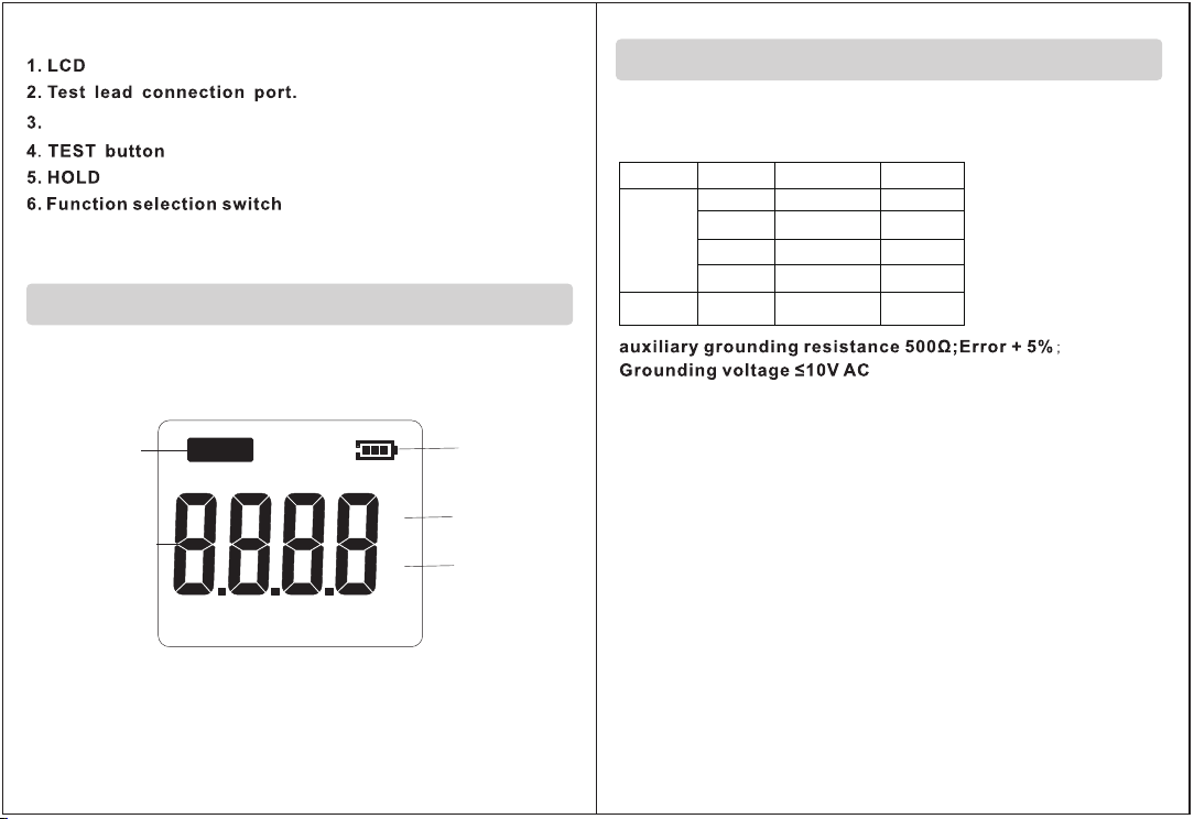
Name of parts(Figure 1)
TEST
HOLD
HV
PRESS
TO TE ST
CAT.III 600V
LOCK
OFFOFF
2000Ω
(2WIR ES)
2000Ω
200Ω
20Ω
EARTH
E
( )
P SACV
( )
C H
MAX
AC200V
VOLTAGE
①
②
④
⑤
③
⑥
-02- -03-
SAVE
-04- -05-
V
Ω
HOLD
~
Data holding
voltage/
resistance
value display
Battery icon
voltage unit
resistance unit
LCD Displays(Figure2)
Figure2
Specifications
Accuracy
1.2 Application standard:
IEC 61010-1 CAT. Ⅲ 600V Pollution degree 2
CAT. Ⅰ 5000V Pollution degree 2
IEC 61326-1 (EMC standard)
IEC 60529 (IP40)
1.3 measurement method:
(1) Ground voltage measurement: average response
(2) Ground resistance measurement: test signal frequency:
about 820Hz, current: 20Ω about 3.2mA
1.4 Working environment: temperature: 5℃~ 40℃; relative
humidity:≤80 ~ RH (no fog) Altitude≤2000 meters
1.5 Storage conditions: temperature: -20 ~ 60 ℃; relative
humidity:≤70% RH (no fog)
1.6 Power supply: 9V power supply [1.5V (No. 5 alkaline
battery) * 6]
1.1 Measurement range and measurement error
(under condition of 20℃ + 5℃and≤75%RH)
_
Ground
voltage
Ground
resistance
20Ω
200Ω
2000Ω
+(2%+10)
_
2000Ω
(two wires)
200V
+(2%+3)
+(2%+5)
_
+(2%+3)
_
+(2%+5)
0.01Ω
0.1Ω
0.1V
1Ω
1Ω
_
_
Basic
Function Range Resolution
SAVE
-06- -07-
1.7 Overload protection:
Ground resistance: 200V AC (10 seconds)
Ground voltage: 400V AC (30 seconds)
1.8 Insulation resistance: The insulation resistance between
measurement circuit and case is not less than 20MΩ
1.9 Dimensions: 176mm * 77mm * 110mm
2.Operation manual
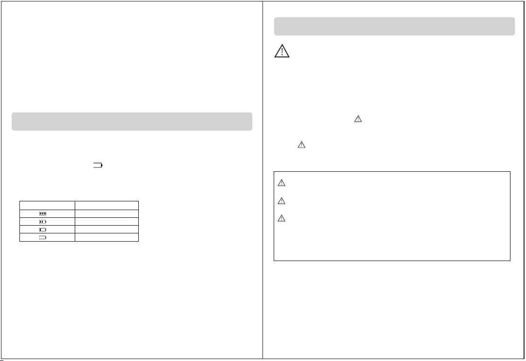
Preparation before measurement
2.1. Check the battery voltage & battery replacement:
Set function selection switch at ground voltage or ground
resistance gear; if “ ” appears on the LCD, it indicates that
battery power is low, and batteries need to be replaced,
otherwise the instrument cannot be used normally.
Battery icon Battery voltage
2.2 Test lead connection
Please make sure that the test lead plug is fully inserted into
test end before measurement. A loose connection may affect
accuracy of measurement value.
>8.45V
>7.72V
>7V
≤7V
Safety warning
WARNING
The safety symbol “ ” has three implications in this
manual. Users should pay special attention to operation
with " " symbol during reading.
DANGER—indicates that an environment and operation
is likely to cause serious or fatal injury.
WARNING—Indicates that an environment and operation
can cause serious or fatal injury.
CAUTION—Indicates that environment and operation can
cause limited injury or damage to the instrument.
Electricity - is dangerous, and can cause personal injury or
death, in order to enable you to use the equipment
correctly and safely, please read the warning message and
safety regulations in this manual carefully before use and
strictly comply with them.

-08- -09-
DANGER
● Do not measure in the flammable and explosive environment,
or sparks may be generated during use, which may cause an explosion.
● Do not make any measurements while the instrument or your
hands are still wet.
● Do not exceed the maximum allowable range when measuring.
● Do not open the battery cover while measuring.
● Do not touch any exposed wires during the test.
● Be sure to turn the test knob back to the OFF position after
measurement.
CAUTION
Implication of relevant icons of this instrument:
● Before measurement, make sure the range switch is
switched to the appropriate position.
● After use, place the measuring selection button in the
"OFF" position. If it is not used for a long time, please
take out the battery to avoid leakage and damage to the
instrument.
● When the instrument is wet, please dry it before storage.
● Please do not store the instrument under high
temperature, high humidity or direct sunlight.
● Please use soft cloth with a small amount of water or
neutral detergent to clean the instrument shell, do not
use friction material or solvent.
WARNING
● The instrument must be operated by a trained and qualified technician
and used under the conditions specified in the manual.
● Please do not open the housing during the test, if there is a failure,
please refer to the professional staff for inspection and maintenance.
● Do not replace the battery when the instrument is wet.
● Make sure all test wires are securely connected to the test port of the
instrument.
● Make sure the device is switched off before opening the battery cover.
● Please check your instrument frequently. If there is any abnormal
phenomenon (broken wire/cracked casing, etc.), please do not do
any operation.
● Please do not replace parts or make any modifications to the
instrument. Please contact the dealer who sells the product for repair.
AC
Grounding
The instrument has double
insulation or reinforced insulation
DC
There may be danger
of electric shock
-10- -11-
Tested
ground end to
Auxiliary ground nail
TEST
HOLD
HV
PRES S
TO TEST
CAT.III 60 0V
LOCK
OFFOFF
2000Ω
(2WI RES)
2000Ω
200Ω
20Ω
EART H
E
P(S)
ACV
C(H)
MAX
AC200 V
VOLTAG E
red
yellow
green
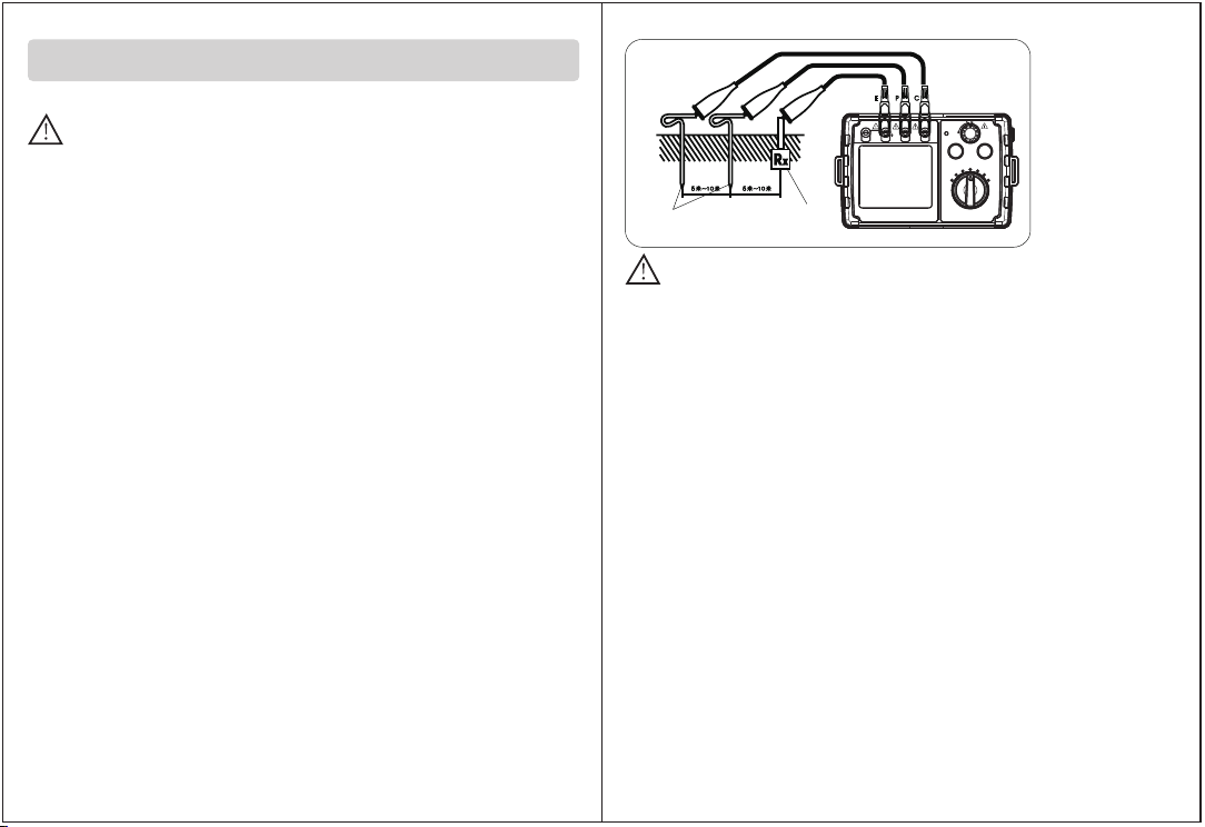
C:Auxiliary electrode
P: Point electrode
E:tested electrical end
Figure3
caveat
Ground voltage test is only performed on the V and E ends, and the
connection between C and P ends must be disconnected, otherwise
it may cause danger or damage to the instrument.
c. Ground resistance test: Rotate function selection switch to 2000Ω
(maximum gear), and press "TEST" button, with LCD displaying
ground resistance value. If the measured resistance value is less
than 200Ω, turn function selection switch to the connection.
20Ω gear of ground resistance is, and LCD displays ground resistance
value. You can also measure in the order of other gears. Be sure to select
suitable gear to measure to make sure the measured value the most accurate.
When you press "TEST" button, status indicator on the button will light up,
indicating that the instrument is under test state.
(Note: if test lead of C or E end have poor contact, auxiliary ground
resistance or ground resistance is too large (such as more than 32KΩ
for 20Ω gear), or the test terminal is open, LCD will display "---- Ω".
At this time, please check whether line connection is good, the soil is
too dry, and the auxiliary grounding nail is reliably grounded.)
When the measured ground resistance is greater than measurement
range of this gear, that is, In case that the 20Ωlevel is between 20.5Ωand
32KΩor the 200Ωlevel is between 205.0Ωand 43KΩor the2000Ωis between
2050Ωand 65KΩ., the LCD will display “OL” (over range).
Measurement method
When the instrument performs ground resistance function test,
a maximum voltage of about 50V~ will be generated between E-C
end s. Do not touch the exposed metal part of test lead and auxiliary
ground nail to avoid electric shock.
caveat
3.1 Accurate measurement (tested with standard test lead):
a. pound P and C ground nails deeply into the ground, line them and
equipment to be measured in a line (straight line) with distance 5
to 10 meters. The connection method is shown in Figure 3:
(Note: Make sure ground nail is pressed in wet soil. If the soil is dry,
add enough water; stone or sand must also be wet before testing.
If it is difficult to make auxiliary ground piles in concrete areas of
urban areas, you can lay two steel plates of 25cm*25cm (or use
existing auxiliary ground nails) flat on the concrete floor and apply
wet towel, pour enough water to replace measuring electrode.
Generally, the measurement can be performed.)
b. Ground voltage test: The function selection switch is screwed to the
ground voltage range, and LCD displays ground voltage measurement.
Status: Insert test leads into V and E ends (do not insert test leads into
other test ends) and then connect to the test point, LCD will display
measured value of ground voltage (note: do not press TEST button
when measuring the ground voltage), if measured value is> 10V,
turn off relevant electrical equipment, and perform ground resistance
test after ground voltage declines, otherwise it will affect test accuracy
of ground resistance.
SAVE

d.
When measuring, press the HOLD key to hold the current data and
display the HOLD symbol. Press the HOLD key again to cancel the data
hold function.
e.Data saving
press the SAVE key to save the reading after measurement and the F-XX
displays on the screen in which the XX denotes the saving No. FULL denotes
the maximum saving data that is as many as 20 pieces is reached.
3.2 Simple measurement (measured with provided simple test line):
By this method, if it is not convenient to use auxiliary ground nail,
exposed low ground resistance can be used as electrode, such as
metal sink, water pipe, common ground of power supply line,
ground terminal of building,All the above can use 2-wire method
(E and P & C ends).The wiring is shown in Figure 4:
TES T
HOL D
HV
PRES S
TO TES T
CAT.III 6 00V
LOCK
OFFOFF
200 0Ω
(2WI RES)
200 0Ω
200Ω
20Ω
EAR TH
E
P(S)
ACV
C(H)
MAX
AC200 V
VOLTAG E
Figure4
Primary
transformer
Secondary
transformer
red
green
Reference
ground end
Measured
ground end
When this method is applied, P and C end are actually shorted together.
DANGER
When taking ground point of commercial power system as reference
point test, please be careful of electrical hazard.
Data hold function
-12- -13-
Note: If auxiliary
ground nail used by this instrument is bent or touches other
things, the reading will be affected. When connecting test
lead, be sure to clean auxiliary ground nail first. If the
resistance of the auxiliary ground nail is too large, it will
cause reading errors.
f.Data review
Long press on SAVE key allows to enter into mode of reviewing the data saved,
the data saved along with their respective saving No. will be displayed on
screen in turn, short press the SAVE/HOLD key to switch between the last/next
data saved, long press on the SAVE key again is to exit this review mode. NULL
denotes no data saved.
g.Data clearance
Long press on the HOLD key until it displays … . then long press on the SAVE
key until its display CLr from the … which denotes the clearance of the
data saved.
SAVE

4.1.2 Case cleaning
Alcohol, diluent, etc. have a corrosive effect on instrument case,
especially the window; so when cleaning instrument case, wipe it
gently with wet towel.
4.1.3 Please prevent the instrument from getting wet.
4.2 Maintenance
4.2.1 If you have any following questions, please contact after-sales
service department of our company's marketing department
or agencies:
A. Instrument components are damaged.
B. LCD is abnormal.
C. In normal use, the error is too large.
D. Button operation failure or confusion.
4.2.2 If it is necessary to repair the instrument, please send the
instrument to a qualified professional maintenance personnel
or designated maintenance department.
Special statement:
a.Used batteries must be disposed of in accordance with local
laws or regulations
b.The company is not liable for any derivative results of using
this product.
c.The company reserves the right to update and modify the
design specifications and content of this product, and it is
subject to change without notice!
-15--14-
3. Other items
Maintenance and warranty
4.1 Maintenance
4.1.1 Battery replacement and maintenance
(Please refer to Figure 5) If low voltage indicator appears, replace
batteries in time as following steps;
a. Turn off the instrument and remove relevant test leads.
b. Unscrew one screw at the bottom of battery door, and then
open the door
c. Please replace all six used batteries, put in new batteries, and pay
attention to polarity of batteries.
d. After replacing batteries, please install battery door and tighten
screws.
When the instrument is not used for a long time, please remove
batteries to prevent battery leakage and corrosion of battery
case and pole pieces.
DIGITAL EARTH
RESISTANCE TESTER
Figure5
Other Benetech Test Equipment manuals


