Woodward 8909-041 User manual

Product Manual
55021
(Revision G, 6/2023
)
Original Instructions
EG Actuator Tester
Models 8909-041 and 8909-059
Installation and Operation Manual
Released

General
Precautions
Read this entire manual and all other publications pertaining to the work to be
performed before installing, operating, or servicing this equipment.
Practice all plant and safety instructions and precautions.
Failure to follow instructions can cause personal injury and/or property damage.
Revisions
This publication may have been revised or updated since this copy was produced.
The latest version of most publications is available on the Woodward website.
http://www.woodward.com
If your publication is not there, please contact your customer service
representative to get the latest copy.
Proper Use
Any unauthorized modifications to or use of this equipment outside its specified
mechanical, electrical, or other operating limits may cause personal injury and/or
property damage, including damage to the equipment. Any such unauthorized
modifications: (i) constitute "misuse" and/or "negligence" within the meaning of
the product warranty thereby excluding warranty coverage for any resulting
damage, and (ii) invalidate product certifications or listings.
Translated
Publications
If the cover of this publication states "Translation of the Original Instructions"
please note:
The original source of this publication may have been updated since this
translation was made. The latest version of most publications is available on the
Woodward website.
www.woodward.com/publications
Always compare with the original for technical specifications and for proper and
safe installation and operation procedures.
If your publication is not on the Woodward website, please contact your customer
service representative to get the latest copy.
Revisions—A bold, black line alongside the text identifies changes in this publication since the
last revision.
Woodward reserves the right to update any portion of this publication at any time. Information provided by Woodward is
believed to be correct and reliable. However, no responsibility is assumed by Woodward unless otherwise expressly
undertaken.
Manual 55021
Copyright © Woodward, Inc. 1984–2023
All Rights Reserved
Released

Manual 55021 EG Actuator Tester
Woodward 3
Contents
WARNINGS AND NOTICES.......................................................................................................4
ELECTROSTATIC DISCHARGE AWARENESS........................................................................6
CHAPTER 1. EG ACTUATOR TESTER OPERATION...............................................................7
Compensated Mode.................................................................................................................................... 16
Oil Pump and Oil Motor Units...................................................................................................................... 19
Maintenance, Functional Checks, and Calibration ..................................................................................... 19
Troubleshooting Guide................................................................................................................................ 23
CHAPTER 2. PRODUCT SUPPORT AND SERVICE OPTIONS ..............................................24
Product Support Options............................................................................................................................. 24
Product Service Options ............................................................................................................................. 24
Returning Equipment for Repair ................................................................................................................. 25
Replacement Parts...................................................................................................................................... 25
Engineering Services .................................................................................................................................. 26
Contacting Woodward’s Support Organization ........................................................................................... 26
Technical Assistance .................................................................................................................................. 27
REVISION HISTORY................................................................................................................28
Illustrations and Tables
Figure 1-1. Magnetic Pickup Connection for Diesel Governor Test Stands ................................................. 8
Figure 1-2. EG Actuator Tester Panel........................................................................................................... 8
Figure 1-3. Cable Assemblies for Connecting EG Actuator Tester to Actuator.......................................... 10
Figure 1-4. Test Hookup for Proportional Actuators ................................................................................... 15
Figure 1-5. Schematic of a Proportional Actuator ....................................................................................... 16
Figure 1-6. Test Hookup for Compensated Actuator .................................................................................. 17
Figure 1-7. Schematic of a Compensated Actuator .................................................................................... 17
Figure 1-8. Connection of Resistor to Transducer Connector .................................................................... 21
Figure 1-9. Transducer Connected to DC Meter......................................................................................... 21
Figure 1-10 Location of P1 and P2 ............................................................................................................. 22
Table 1-1. EG Actuator Tester Specifications............................................................................................... 7
Table 1-2. EG Proportional Actuator Setup of Switches and Adjustments................................................... 9
Table 1-3. EG Actuator Tester 8909-059 Cables........................................................................................ 14
Table 1-4. EG Compensated Actuator Setup of Switches and Adjustments.............................................. 18
Released

Manual 55021 EG Actuator Tester
Woodward 4
Warnings and Notices
Important Definitions
This is the safety alert symbol used to alert you to potential personal injury hazards. Obey all
safety messages that follow this symbol to avoid possible injury or death.
•DANGER - Indicates a hazardous situation, which if not avoided, will result in death or serious injury.
•WARNING - Indicates a hazardous situation, which if not avoided, could result in death or serious
injury.
•CAUTION - Indicates a hazardous situation, which if not avoided, could result in minor or moderate
injury.
•NOTICE - Indicates a hazard that could result in property damage only (including damage to the
control).
•IMPORTANT - Designates an operating tip or maintenance suggestion.
Lockout/Tagout
LOTO
Ensure that personnel are fully trained on LOTO procedures prior to
attempting to replace or service equipment on a “live” running
engine. All safety protective systems (overspeed, over temperature,
overpressure, etc.) must be in proper operational condition prior to
the start or operation of a running engine. Personnel should be
equipped with appropriate personal protective equipment to
minimize the potential for injury due to release of hot hydraulic
fluids, exposure to hot surfaces and/or moving parts, or any moving
parts that may be activated and are located in the area of control of
the unit.
Overspeed /
Overtemperature /
Overpressure
The engine, turbine, or other type of prime mover should be
equipped with an overspeed shutdown device to protect against
runaway or damage to the prime mover with possible personal injury,
loss of life, or property damage.
The overspeed shutdown device must be totally independent of the
prime mover control system. An overtemperature or overpressure
shutdown device may also be needed for safety, as appropriate.
Personal Protective
Equipment
The products described in this publication may present risks that
could lead to personal injury, loss of life, or property damage.
Always wear the appropriate personal protective equipment (PPE) for
the job at hand. Equipment that should be considered includes but is
not limited to:
•Eye Protection
•Hearing Protection
•Hard Hat
•Gloves
•Safety Boots
•Respirator
Always read the proper Material Safety Data Sheet (MSDS) for any
working fluid(s) and comply with recommended safety equipment.
Released

Manual 55021 EG Actuator Tester
Woodward 5
Start-up
Be prepared to make an emergency shutdown when starting the
engine, turbine, or other type of prime mover, to protect against
runaway or overspeed with possible personal injury, loss of life, or
property damage.
Automotive
Applications
On- and off-highway Mobile Applications: Unless Woodward's
control functions as the supervisory control, customer should install
a system totally independent of the prime mover control system that
monitors for supervisory control of engine (and takes appropriate
action if supervisory control is lost) to protect against loss of engine
control with possible personal injury, loss of life, or property
damage.
IOLOCK
IOLOCK: driving I/O into a known state condition. When a control
fails to have all the conditions for normal operation, watchdog logic
drives it into an IOLOCK condition where all output circuits and
signals will default to their de-energized state as described below.
The system MUST be applied such that IOLOCK and power OFF
states will result in a SAFE condition of the controlled device.
•Microprocessor failures will send the module into an IOLOCK
state.
•Discrete outputs / relay drivers will be non-active and
de-energized.
•Analog and actuator outputs will be non-active and de-energized
with zero voltage or zero current.
Network connections like CAN stay active during IOLOCK. This is up
to the application to drive actuators controlled over network into a
safe state.
The IOLOCK state is asserted under various conditions, including:
•Watchdog detected failures
•Microprocessor failure
•PowerUp and PowerDown conditions
•System reset and hardware/software initialization
•PC tool initiated
NOTE—Additional watchdog details and any exceptions to these
failure states are specified in the related section of the product
manual.
Released

Manual 55021 EG Actuator Tester
Woodward 6
Battery Charging
Device
To prevent damage to a control system that uses an alternator or
battery-charging device, make sure the charging device is turned off
before disconnecting the battery from the system.
Electrostatic Discharge Awareness
Electrostatic
Precautions
Electronic controls contain static-sensitive parts. Observe the
following precautions to prevent damage to these parts:
•Discharge body static before handling the control (with power to
the control turned off, contact a grounded surface and maintain
contact while handling the control).
•Avoid all plastic, vinyl, and Styrofoam (except antistatic
versions) around printed circuit boards.
•Do not touch the components or conductors on a printed circuit
board with your hands or with conductive devices.
To prevent damage to electronic components caused by improper
handling, read and observe the precautions in Woodward manual
82715, Guide for Handling and Protection of Electronic Controls,
Printed Circuit Boards, and Modules.
Follow these precautions when working with or near the control.
1. Avoid the build-up of static electricity on your body by not wearing clothing made of synthetic
materials. Wear cotton or cotton-blend materials as much as possible because these do not store
static electric charges as much as synthetics.
2. Touch your finger to a grounded surface to discharge any potential before touching the control, smart
valve, or valve driver, or installing cabling connectors. Alternatively, ESD mitigation may be used as
well: ESD smocks, ankle or wrist straps and discharging to a reference grounds surface like chassis
or earth are examples of ESD mitigation.
•ESD build up can be substantial in some environments: the unit has been designed for
immunity deemed to be satisfactory for most environments. ESD levels are extremely
variable and, in some situations, may exceed the level of robustness designed into the
control. Follow all ESD precautions when handling the unit or any electronics.
oI/O pins within connectors have had ESD testing to a significant level of immunity to
ESD, however do not touch these pins if it can be avoided.
Discharge yourself after picking up the cable harness before installing it as a
precaution.
oThe unit is capable of not being damaged or improper operation when installed to a
level of ESD immunity for most installation as described in the EMC specifications.
Mitigation is needed beyond these specification levels.
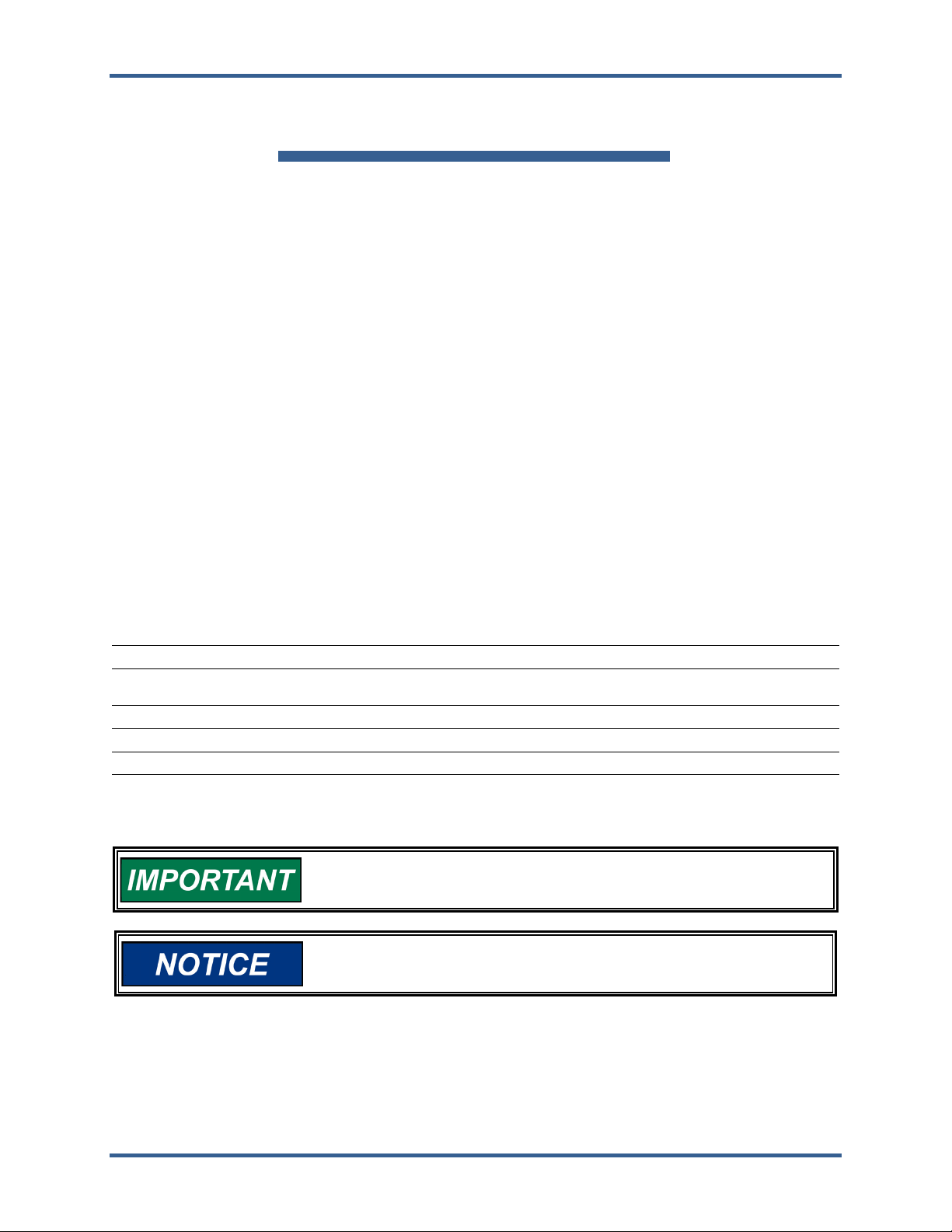
External wiring connections for reverse-acting controls are identical
to those for direct-acting controls.
Released

Manual 55021 EG Actuator Tester
Woodward 7
Chapter 1.
EG Actuator Tester Operation
The EG Actuator Tester is used to test EG proportional actuators and EG compensated actuators. It is
used in conjunction with a magnetic pickup and electronic digital counter on the test stand. See
Figure 1-2 for interconnections. In addition, the tester is used to center the pilot-valve plunger to pilot-
valve port. Figure 1-1 shows interconnections between the EG Actuator Tester, governor magnetic
pickup, and the counter.
The current meter Is connected for reading current supplied to the actuator coil.
Power supply in the EG Actuator Tester is as follows:
•28 VDC Power Supply (relays)
•±15 VDC Power Supply (electronics)
EGB Speed Setting
When working with an EGB P or C governor/actuator, the section (mechanical or electrical) with the
lowest speed setting will control speed. Set the mechanical governor speed about 5% higher than the
electric actuator so the actuator can control speed. This results in the mechanical governor power piston
moving to maximum position. EGB systems with droop can exhibit a fuel limiting effect if the mechanical
speed is set too close to the electrical speed setting. Should this be suspected, increase the mechanical
speed setting to be sure there is not interference.
Specifications
Table 1-1. EG Actuator Tester Specifications
Line Input
115 VAC 50 or 60 Hz
Tachometer Input
3V peak-to-peak minimum sine or square wave
External Voltmeter
Any digital or analog dc voltmeter with minimum
impedance of 10 000 Ω/V.
Proportional Actuator Current
0 to 300 mAdc or more
Compensated Actuator Voltage
–10 VDC to +10 VDC
Transducer Centering Current
380 mA total into 35 Ω
Digital Display
190 mA per coil into 17.5 Ω
1% accuracy in either proportional or
compensated
Transducer centering current will vary with line voltage. (100V
centering current will drop to 320 mA.)
Do not leave the transducer output connected to a short circuit.
Overheating can damage the actuator.
Released

Manual 55021 EG Actuator Tester
Woodward 8
Figure 1-1. Magnetic Pickup Connection for Diesel Governor Test Stands
Figure 1-2. EG Actuator Tester Panel
Integrating–Compensating
Many electric controls require an actuator, which operates at a null voltage for steady state conditions.
These actuators will increase fuel in response to a positive control signal and decrease fuel in response
to a negative control signal. Reverse acting actuators will maximize its fuel in response to a negative
control signal. All of these actuators require adjustable compensation to provide stability of operation.
Because the Woodward designation of most integrating actuators is shown with a “C,” the term
“compensated” is used interchangeably with “integrated” in the discussion of test equipment for actuators.
Compensation has been provided in some recent models of proportional actuators, but in every case the
P is also included in the designation, as in EG-10PC.
Proportional Mode
Introduction
Proportional actuators respond to control signals which are in direct proportion to the total fuel setting
position needed by the actuator. The signals generally range from 20 to 200 mA. Direct acting
proportional actuators are at minimum fuel at the 20 mA signal. Reverse acting proportional actuators are
at maximum fuel at 20 mA and at minimum fuel at 200 mA control signal.
Setup
The initial setup of switches and adjustments for an EG Proportional Actuator is shown in Table 1-2.
Released

Manual 55021 EG Actuator Tester
Woodward 9
Table 1-2. EG Proportional Actuator Setup of Switches and Adjustments
EG Actuator Tester Switch or Dial
Initial Switch and Dial Settings
Power ON/OFF switch
OFF position
Center/slug normal switch
Normal position
EG-P/EG-C switch
EG-P position
Stability potentiometer
Full clockwise position
(315° movement)
Gain potentiometer
Mid position (315° movement)
Speed setting potentiometer
for direct acting actuator
At 10-turn position
(full counterclockwise position)
Speed setting potentiometer
for reverse acting actuator
At 10-turn position
(full clockwise position)
Connection
Select the correct cable assembly from Figure 1-3. Connect the actuator to the actuator tester with the
correct cable assembly. Connect the actuator tester to 115 VAC supply and turn power ON.
Released

Manual 55021 EG Actuator Tester
Woodward 10
Figure 1-3. Cable Assemblies for Connecting EG Actuator Tester to Actuator
Released

Manual 55021 EG Actuator Tester
Woodward 11
Cables
Two 4-foot (1.2 m) cables are used to extend the connection on the test box to the table of the test stand.
5400-531 reverses the 3-pin wiring from the test box to the table but provides the same type of plug as is
on the test box.
5400-515 provides a direct copy of the plug on the test box at the end of a 4-foot (1.2 m) extension cord.
Notice that 5400-531 and 5400-515 are identical except for the reversed wiring available from 5400-
531.
Two interconnected cables, each 9 inches (229 mm) long, connect to the 3-pin plugs on the end of the
selected 4-foot (1.2 m) extension cords. The interconnected cables terminate with a Jones plug, which
connects to the final actuator cable or to certain actuators after the cover is removed.
5400-560 converts from the 3-pin plug to a Jones plug directly.
Released

Manual 55021 EG Actuator Tester
Woodward 12
5400-519 converts the output of the 3-pin plug on the end of the 4-foot (1.2 m) extension cord to a Jones
plug but reverses the location of the positive and negative pins.
Three 8-inch (203 mm) conversion cords are provided to allow connection between the Jones plug to the
various plugs used on actuators. Some of these cords reverse wiring between the Jones plug on one end
and the actuator plug on the other end, requiring the proper assembly of the 4-foot (1.2 m) and 9-inch
(229 mm) cables to complete the connection.
5400-521 Jones plug to 2-pin connection on actuator. Reverses polarity.
5400-523 Jones plug to 10-pin connector at actuator. Reverses polarity.
5400-541 Jones plug to 14-pin connector at actuator. Direct polarity.
Released

Manual 55021 EG Actuator Tester
Woodward 13
5400-562 Jones plug to 4-pin connector at actuator. Does not reverse polarity.
A special cable is provided to make testing of integrating actuators possible.
5400-518 connects from the test box to the BNC connection on a Woodward electric drive test stand to
permit use of the test stand speed feedback with the test box and actuator.
A special cable is available for use with the 3199 actuator.
5415-519 is used between the Jones plug and the actuator plug. A pigtail is provided connecting to the
center sap on the actuator coil. This connection is used to center the slug in the coil. Other cables may be
constructed to connect to Sure Seal and 10-pin plugs used on some 3199 actuators.
The newer version of the EG Tester, 8909-059, has a new set of cables that allows connection directly
from the tester to the actuator/governor without using two or three interconnecting cables. This will help
avoid confusion. The operation of the EG Tester itself is identical to the previous version, 8909-041. The
cables include attachments to 2-, 3-, 4-, and 10-pin MS connectors, as well as to the Sure Seal connector
used on newer Caterpillar applications. There are two cables to connect to the internal Jones plug on the
inside of EGB governors. Cables are available for 14-pin connectors, but they are not included in the
tester for cost reasons, as they are not standard.
Released

Manual 55021 EG Actuator Tester
Woodward 14
Cables for 8909-059 EG Actuator Tester
Table 1-3. EG Actuator Tester 8909-059 Cables
Actuator Model
Cable Part Number
Cables to Outside Plug on Actuator
EGB2P direct & reverse acting
5400-543
EGB10P, 29P, 58P, 200P:
10-pin direct & reverse acting
5400-545
EGB10P, 29P, 58P, 200P:
14-pin direct & reverse acting
5400-547*
EGB2C 2-pin plug
5400-557
EGB2C 3-pin plug
5400-531
EGB10C, 29C, 58C 10-pin
5400-559
EGB10C, 29C, 58C 14-pin
5400-561*
EG3P, 10P, 3PC, 10PC
5400-551
EG-P with Sure Seal connector 5400-549
EGR 5400-531
EG3C, 10C 5400-531
UA, UG Actuator, UG40 Actuator
5400-515
PGEG
5400-551
TG-13E
5400-551
Cables to Inside Jones Plug
EGB2P direct acting
5400-553
EGB2P reverse acting
5400-555
EGB10P, 29P, 58P, 200P direct acting
5400-553
EGB10P, 29P, 58P, 200P reverse acting
5400-555
EGB2C
5400-553
EGB10C, 29C. 58C
5400-553
(*) Available, but not included with tester
Centering and Terminal Shaft Travel
1. Attach protractor to terminal shaft.
2. Insert a 7/64-inch Allen wrench through clearance hole In cover, through hollow center of spring
seat adjustment, and engage centering screw (see Figure 1-5).
3. Turn centering screw clockwise until it bottoms GENTLY.
4. Back centering screw out 1 and 1/4 turns for a starting adjustment.
5. Turn power ON/OFF switch ON. Be sure the Speed Adjustment is at 0.
6. Turn spring seat adjustment screw (1/8-inch hex) until actuator terminal shaft is near mid-stroke.
7. Operate Center Slug/Normal switch to “Center Slug” position and observe terminal shaft.
Terminal shaft should not move. If it does move, adjust centering screw (7/64-inch hex) until
terminal shaft does not move when switching from “Center Slug” to “Normal”.
8. Do not exceed 200 mA after this point.
9. Set Center Slug/Normal switch to “Normal” position and EG-P/EG-C switch to EG-P position.
10. Adjust speed setting potentiometer to milliamp current required at minimum fuel per
specifications (typically 20 mA).
Released

Manual 55021 EG Actuator Tester
Woodward 15
11. Turn spring seat adjustment counterclockwise until actuator terminal shaft is at minimum fuel
position, then turn the seat clockwise until the shaft moves 2 to 3 degrees from its minimum fuel
position towards maximum fuel position.
12. See specifications and adjust potentiometer to milliamp setting for maximum terminal shaft
position.
13. Terminal shaft should move to maximum-fuel position.
•If it does, disconnect actuator tester and oil supply line.
•If it does not, continue with step 14.
14. Remove cover and move feedback bracket toward the terminal shaft to increase terminal shaft
travel and away from the terminal shaft to decrease terminal shaft travel.
15. Repeat the adjustments at minimum and maximum current alternately, until no further
adjustment is required at either point and correct degrees of rotation are attained.
16. Replace cover and recheck range.
17. If adjustment is required, adjust spring seat through vent hole in cover. Use a 1/8-inch Allen
wrench to make adjustment.
18. Disconnect test circuit and oil supply line. Remove protractor.
Figure 1-4. Test Hookup for Proportional Actuators
Released

Manual 55021 EG Actuator Tester
Woodward 16
Figure 1-5. Schematic of a Proportional Actuator
Current Supply
•360 mA non-adjustable when in center slug position.
•0 to 350 mA in proportional mode. Adjustable with speed adjustment control.
Compensated Mode
General Information
Testing a compensated (integrated) electric actuator or governor/actuator requires a magnetic pickup kit
assembly. Testing an EGR actuator requires a remote servomotor mounted on the test stand. Figure 1-6
shows the test hookup for a compensated actuator.
Released

Manual 55021 EG Actuator Tester
Woodward 17
Figure 1-6. Test Hookup for Compensated Actuator
Use the actuator tester to center the pilot-valve plunger control land with the pilot-valve bushing control
port (see Figure 1-7). If the centering is not correct, null voltage shifts will occur, resulting in a change of
prime mover speed. For a theoretical system, null voltage would be zero volts when the speed signal
derived from the prime mover is equal to the speed reference signal. If an electrical failure occurs, the
pilot valve will remain centered, and the prime mover will run uncontrolled.
Therefore, Woodward actuators are spring biased at the pilot valve to go to maximum or minimum fuel on
loss of control signal, depending on customer requirements, The 1/8-inch Allen screw above the magnet
adjusts tension on the biasing (centering) spring. This spring bias results when a small voltage is present,
and the system is on speed. The voltage electrically balances the spring bias. A reading of about 1V is
normal.
Specifications of a particular actuator can be obtained from Woodward. Be sure you have manuals for the
governors being tested.
Figure 1-7. Schematic of a Compensated Actuator
Released

Manual 55021 EG Actuator Tester
Woodward 18
Initial Connections
Select the correct cable assembly from Figure 1-3. Connect the actuator to the actuator tester with the
correct cable assembly. Connect the actuator tester to 115 VAC supply and turn power ON.
Setup
The initial setup of switches and adjustments for an EG Compensated Actuator is shown in Table 1-4.
Table 1-4. EG Compensated Actuator Setup of Switches and Adjustments
EG Actuator Tester Switch or Dial
Initial Switch and Dial Settings
Power ON/OFF switch
OFF position
Center/slug normal switch
Normal position
EG-P/EG-C switch
EG-C position
Stability potentiometer
Full clockwise position
(315° movement)
Gain potentiometer
Mid position (315° movement)
Speed setting potentiometer
At 0-turn position
(full counterclockwise position;
10-turn movement)
Centering
1. Install actuator on test stand in same position as it is on prime mover (see Figure 1-6).
2. Insert a 7/64-inch Allen wrench through clearance hole in cover, through hollow center of
adjustable spring seat and engage centering screw (see Figure 1-7).
3. GENTLY bottom centering screw, then back out 1 and 1/4 turns for a starting adjustment.
4. Turn power switch to ‘ON” position.
5. Increase speed-setting potentiometer until governor controls test-stand speed.
6. Adjust spring seat (1/8 Inch Allen wrench) until voltage reads approximately zero volts.
7. Tune gain and stability for optimum performance. Turn gain control clockwise as necessary to
maintain stable but fast control.
8. Move center slug switch between normal and center-slug position. Note speed at each position.
The object is to have the same speed in both switch positions and no
change in null voltage. Acceptable limits are 5 rpm difference and
0.2V change in null voltage.
9. Adjust centering screw to eliminate any speed difference between the two switch positions of
Center Slug/Normal.
10. If speed increases when switching from Normal to Center Slug, turn centering screw clockwise
(counterclockwise for reverse-acting actuators) about 1/8 turn.
11. Adjust null voltage screw clockwise (counterclockwise for reverse-acting actuators) about 1/8 turn
to maintain null voltage close to zero volts.
12. Adjust null voltage screw to provide a null voltage of either a positive or negative value of one
volt, or per test specification.
a. For the actuator to go to maximum-fuel position on loss of electrical signal, adjust null-
voltage screw to positive one volt.
b. For the actuator to go to minimum-fuel position on loss of electrical signal, adjust null-
voltage screw to negative one volt.
Released

Manual 55021 EG Actuator Tester
Woodward 19
13. Check operation by turning power switch to OFF position on actuator tester and observe direction
of terminal-shaft travel.
14. If instability occurs between stand control and actuator tester, reverse jacks of cable assembly
5400-518. This ensures correct grounding to eliminate noise interference.
15. If EGB-10C governor/actuator is equipped with an internal shutdown solenoid or with a two-
solenoid speed setting, modify 5400-523 cable assembly at EGB-10C connector end so correct
voltages can be applied to these solenoids.
16. Refer to the correct actuator wiring schematic for connections, and to Woodward manual 37729
for adjustment and operation of a two-solenoid speed setting assembly.
Oil Pump and Oil Motor Units
Some actuators are driven by the engine and have their own oil
pumps. Other actuators use an oil motor or electric motor drive.
These types do not require a test stand drive.
Oil Pump Unit
1. Turn on oil supply after mounting unit on test stand.
2. Allow a few minutes for actuator to warm up.
3. Drive actuator at 2000 rpm or at operating speed.
Oil Motor Unit
1. Mount unit on the test stand, turn on oil supply and allow a few minutes for actuator to warm up.
2. Make sure oil motor is operating by observing if splined end of pilot-valve bushing is rotating.
Maintenance, Functional Checks, and Calibration
External Voltmeter
Two jacks, marked EXT-VOLTMETER, are provided for an external analog voltmeter, if analog reading is
desired. The reading is the actual dc voltage going to the coil.
Digital Readout
In the EG-C mode, the digital meter shows dc volts to two decimal places.
In the EG-P mode, the digital shows dc current in mA to three digits.
Fuse Replacement
HIGH VOLTAGE—Disconnect the power cord from the power source
to avoid possibly dangerous electrical shock.
If the lights fail and the box does not function, check the fuse.
Check the fuse by removing the four screws on the back panel and the top cover. The fuse is located on
the circuit board and is a 0.5 A fast blow. Littlefuse number 3AG 1/2 A.
Released

Manual 55021 EG Actuator Tester
Woodward 20
Lamp Replacement
To replace a lamp:
1. Grasp sides of lens lightly with pliers and pry left or right. Lens should come off.
2. Remove lamp by pulling straight out on metal tab above or below lamp.
3. Replace with Chicago Miniature lamp, Type 85, 28V.
4. Snap lens back into position.
Setup
1. Connect a power cord to 115 VAC.
2. Connect a function generator between the blue and white jack on the front panel.
3. Set the output of the function generator for a 3 Vrms sine wave at 1kHz ±5Hz.
MODE Check
1. Press ON switch to ON position.
a. ON switch should light green.
b. NORMAL switch should light yellow.
2. Press NORMAL switch in the CENTER SLUG position.
a. Switch should light green.
b. Release switch to Normal.
3. Press EG-P/EG-C switch in the EG-P position.
a. Switch should light green.
b. Digital meter should display 3 digits to represent current mode.
4. Press EG-P/EG-C switch in the EG-C mode.
a. Switch should light yellow.
b. Digital meter should display a 3- or 4-digit figure with 2 decimal places to represent
voltage mode.
Functional Check
1. Set the GAIN pot to full CCW
2. Set the STABILITY pot to full CW
3. Ensure the EG Actuator Tester is in EG-C mode.
•Adjust the speed-setting pot from full counterclockwise to full clockwise. The meter
reading should vary from 2.75V ±2.00V (CCW) to –12.81V ±2.00V (CW).
4. Connect an external voltmeter to the external voltmeter jacks and set the SPEED pot to full
CCW. Reading on external voltmeter should be within 1 percent of digital display (in EG-C
mode). Remove external meter.
5. EG-P mode of operation
•Disconnect the function generator
•Verify the GAIN pot to full CCW
•Verify the STABILITY pot to full CW
•Connect a 35 Ω resistor (30 Ω to 60 Ω will work) to A and B of the transducer connector
(see Figure 1-8). Adjustment of speed setting pot should vary the current reading on the
digital display from 000 to -300 mA or more (into 35 Ω).
6. Move resistor to C and B of transducer connector. Turn speed setting pot counterclockwise to 0.
Press NORMAL switch to center slug. Meter should display 300 mA ±25 mA (at 35 Ω).
Released
This manual suits for next models
1
Table of contents
Other Woodward Test Equipment manuals
Popular Test Equipment manuals by other brands

Agilent Technologies
Agilent Technologies E5515BU-863 Installation note

Rohde & Schwarz
Rohde & Schwarz RTE Series Getting started

turck
turck IMX12-AO01 Series quick start guide

Tempo Fitness
Tempo Fitness 600LS user manual

Lecom
Lecom MachineTest MT300E operating instructions

Kikusui
Kikusui PFX2731S Operation manual