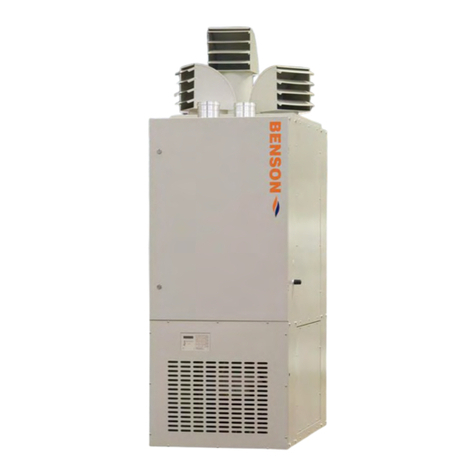
BENSON HEATING CVO 70 Quick start guide

Installation, use and maintenance instructions
BENSON
HEATING
Light oil warm air heater
Machinery Directive
EEC 89/392
EEC 91/368
EEC 93/44
EEC 93/68
MODEL PRODUCT CODE
CVO 55 3NDGBCD015
CVO 70 3NDGBCD020
CVO 100 3NDGBCD030
Fuel Light oil
Country of destination Great Britain
Serial number and year of construction See machine ID plate
CVO Series

2
Dear Customer,
Thank you for requesting a Benson Heating warm air heater from your installer. In doing so you have selected one of the
best products on the market, one which will provide you with all the undisputed advantages of greater indoor comfort. This
manual provides information and advice for its proper installation, use and maintenance. To ensure long-lasting
performance we recommend that you read the entire manual carefully. Store this manual in a safe place for future
consultation.
WARNING
Always make sure the unit is accompanied by this manual so that it can be consulted by the user, installer and any
specialised Assistance Service personnel.
Before reading this manual please note that the warm air heater warranty is only valid where the unit has been installed by
QUALIFIED PERSONNEL ONLY.
This unit has been designed for indoor heating purposes only. IT IS FORBIDDEN TO USE THE UNIT FOR ANY
PURPOSES OTHER THAN THAT FOR WHICH IT HAS BEEN SPECIFICALLY DESIGNED.
Fumes and/or odours may be emitted during the first few hours of operation owing to evaporation of the liquid which
protects the heat exchanger; this is quite normal and will cease after a short time.
The room in which the unit is installed should be properly ventilated.
USEFUL ADVICE:
Installation and maintenance must be carried out by personnel qualified as per Italian Law n° 46 of 5th march 1990 and in
compliance with UNI-CIG 7129 and 7131, amendments included.
Your safety starts here:
Improper installation can cause damage to persons, animals and objects. The manufacturer cannot be held liable for any
such damages.
After removing the unit from its packaging make sure it has not been damaged during transport and that no parts are
missing; if in doubt do not use the unit and contact your dealer.
Dispose of packaging (plastic bags, expanded polystyrene etc.) properly. Keep such packaging away from children as it is
dangerous.
Do not install the unit near inflammable materials.
Fix and protect fuel feed lines properly.
Fuel feed lines and electrical power lines must not cause obstruction or cause personnel to trip up.
The unit must be serviced at least once a year by qualified personnel and in any case by a specialised Assistance Service
firm.
If the installation area is poorly lit use additional lighting when carrying out installation/maintenance tasks.
Never let children or incapable persons use the unit unless under adult supervision.
Do not install the unit in areas with an “aggressive” atmosphere.
Do not get the unit wet, install it in a damp area or where it may be splashed by water or other liquids.
Never place any objects on top of the unit.
Do not touch the chimney flue connector duct during routine use as this can become extremely hot.
Do not insert anything in the cover grating and/or fume outlet duct.
In the event of prolonged absence close the main fuel cut-off valve.
DO NOT CARRY OUT ANY WORK ON THE UNIT YOURSELF
As with all Benson Heater units, use original spare parts only.
The manufacturer cannot be held liable for any damages caused by improper, erroneous or unreasonable use of the unit or
the use of non-original parts/materials.
The manufacturer cannot be held liable for any errors in the translation of this manual which result in erroneous
interpretation.
The manufacturer cannot be held liable for any inobservance of instructions contained in this manual or the consequences
of doing any work not specifically described therein.
Before carrying out any cleaning or maintenance work:
- close all fuel valves/taps.
- disconnect the unit from the electrical power supply via the main unit switch and/or any power line breakers.
- make sure the heat exchanger has cooled so that there is no risk of being burnt. Do not use adapters, multiple sockets
and/or extension leads to connect up to the mains power supply. To connect to the mains install an omnipolar switch as per
the safety standards in force.
Use of any electrical device involves observance of the following essential rules:
Do not touch the unit with wet/damp body parts or if barefoot.
Do not tug power leads.
Do not leave the unit exposed to atmospheric agents.

3
1. INDEX
Chapter Subject Page
1. CONTENTS 3
2. DESCRIPTION AND CHARACTERISTICS 4
2.1 Description 4
2.2 Technical characteristics 5
2.3 Overall dimensions 5
3. INSTALLATION INSTRUCTIONS 6
3.1 Handling and transport 6
3.1.1 Handling with vehicles/other mechanical devices 6
3.1.2 Handling manually 6
3.2 Removing the packaging 6
3.3 Positioning the unit 7
3.4 Connections 7
3.4.1 Chimney flue connections 7
3.4.2 Fuel line connections 8
3.4.3 Electrical connections 11
3.4.4 Air delivery connections 12
4 ADJUSTING THE UNIT 13
5 CONTROLS 13
6 INSTRUCTIONS FOR USE 13
6.1 Preliminary tasks 13
6.2 Preventive checks 13
6.3 First-time start up 14
7 MAINTENANCE 15
8 ASSISTANCE 16
9 TROUBLESHOOTING 17

4
2. DESCRIPTION AND CHARACTERISTICS
2.1 Description
The CVO Series warm air heater manufactured by BENSON HEATING has been designed to meet a wide range
of heating needs. It is ideal for houses, apartments, offices, shops, restaurants, pubs, laboratories, workshops,
hospital rooms etc. and can diffuse warm air either directly or distribute it via a system of ducts.
The CVO Series warm air heater manufactured by BENSON HEATING uses heat energy provided by internal
combustion and a heat exchanger. A fan generates an air current which flows over the exchanger directly, this
making the use of intermediate fluids unnecessary. This system significantly reduces both initial outlay and
running costs, thus making the unit suitable even in circumstances where it is used only intermittently or
occasionally.
During the summer the unit also provides efficient ventilation.
THE UNIT MUST NOT BE USED FOR PURPOSES OTHER THAN THAT FOR WHICH IT HAS BEEN
DESIGNED.
1. Min-max commutator 8. Rear panel
2. FAN-LIMIT two-way thermostat 9. Tube through-slot
3. Chimney flue inlet 10. Motor
4. Fume ducts 11. Fan
5. Flame control spy-hole 12. Air filter
6. Burner inlet 13. Front panel
7. Combustion chamber 14. Burner

5
2.2 Technical characteristics
CVO 55 CVO 70 CVO 100
Heating capacity input Kw 18.49 23.72 34.13
Btu/h 63.104 80.920 116.403
Efficiency % 88.0 88.2 88.5
Heating capacity output Kw 16.3 20.9 30.2
Btu/h 55.600 71.300 103.000
Air flow at +15°C m3/s 0.24 0.31 0.44
cfm 508 647 940
Thermal head °C 55 55 55
Available low speed Pa 0 0 0
Static medium speed Pa 50 50 70
Pressure high speed Pa 80 80 150
35 Second Gas Oil l/h 1.75 2.24 3.23
Consumption gal/h 0.39 0.50 0.72
28 Second Kerosene l/h 1.81 2.33 3.35
Consumption gal/h 0.40 0.52 0.74
Electricity Supply V/50Hz 230 230 230
Electrical fan power w 150 150 420
Nett Weight(1) Kg 82 97 116
(1) Data refers to unit without burner
2.3 Overall dimensions
MOD. A B H C D ∅
∅∅
∅
CVO 55 350 860 860 210 422 100
CVO 70 390 960 960 250 502 120
CVO 100 430 1.030 1.030 290 592 130

6
3. INSTALLATION INSTRUCTIONS
3.1 Handling and transport
The CVO Series warm air heater manufactured by BENSON HEATING is shipped on a wooden base and is
protected by plastic and cardboard packaging. Any accessories are shipped separately. Handling and transport
must be carried out with the unit in a vertical position. To minimise risk of damage wait until the unit reaches
the installation area before removing the packaging.
3.1.1 Handling with vehicles/other mechanical devices
The CVO Series warm air heater manufactured by BENSON HEATING has been designed to be handled with
the aid of mechanical lifting devices (fork-lift truck, bridge crane with lift harness etc.). It is essential that the pick-
up points indicated in fig. 3.1.1.1 be used.
Should it be necessary to stack the units observe the stacking index indicated on the packaging itself. Make sure
stacks are aligned properly to prevent instability.
WARNING: Personnel should keep a safe distance from the unit during transport, lifting and handling.
Fig. 3.1.1.1 Pick-up points
3.1.2 Handling manually
If handling the unit-plus-packaging set manually, grasp it by its wooden base only. Make sure that the weight of
the unit (as indicated in chapter 2.2) can be lifted and manoeuvred along the route to be taken by available
personnel without difficulty.
3.2 Removing the packaging
To free the unit from the packaging proceed as follows:
remove the strap fixing the unit to the wooden base.
remove the cardboard case by sliding it upwards.
remove the plastic film from the unit cover.
remove the wooden base (not fixed to the unit) by raising the heater a little.
All packaging must be disposed of in compliance with the laws in force.

7
3.3 Positioning the unit
The unit must be positioned on a flat, dry, stable surface capable of bearing the load indicated in the “Technical
Characteristics”.
The position of the warm air heater must be defined by qualified personnel and should take into account the
following:
it should be adjacent to a chimney flue
connection to the fuel line should be easy
it should be near a power socket
there should be sufficient space around the unit to allow maintenance/checks to be effected (see 3.3.1.)
ventilation must comply with the standards in force.
Fig. 3.3.1 Minimum installation distances
Warning!
To prevent accidental contact with moving parts it is forbidden to run the unit without its guard panels fitted.
These are:
Rear inspection panel
Burner cover
3.4 Connections
All connections must be effected by qualified personnel only, in observance of the standards in force. If
necessary, use additional lighting to prevent errors caused by poor visibility in the work area.
3.4.1 Chimney flue connections
A proper burner/heater/chimney flue match provides significant reductions in fuel consumption, makes
combustion more efficient, lowers pollutant emissions provides effective protection against condensation The
chimney flue is thus of primary importance for the system as a whole.
The chimney flue must compulsorily be made of an impermeable material that is resistant to heat and
condensation (Italian law 1083 DM of 7.6.73 – G.U. 203 and UNI-CIG 7129 p. 3116); it must also be smooth,
insulated, be as vertical as possible and sized in accordance with height and power ratings as per legislation in
force. Improperly sized or poorly shaped flues amplify combustion noise, give rise to condensation problems and
interfere with combustion parameters, thus aiding the formation of soot and incrustations.

8
The CVO Series warm air heater manufactured by BENSON HEATING must be connected to chimney flues
having the following specifications (see fig. 3.4.1.1):
cross-section equal to or greater than flue connector duct
smooth internal surface
maximum horizontal length of 1 m
no tight bends or changes in cross-section
minimum vertical length of 3 m.
Fig. 3.4.1.1 Flue connections
3.4.2 Fuel line connections
Light oil
To effect fuel line connections it is necessary to connect the two flexible burner pump hoses (intake and return)
to a fuel tank according to the instructions given in fig. 3.4.2.2. Proceed as follows:
remove the burner cover.
remove the intake and return plugs positioned on the lower part of the burner pump body (see fig. 3.4.2.1).
fit the two fuel flex hoses (supplied) and insert them in the slots designed to receive them from both sides
(see fig. 3.4.2.3).
connect up the flex hoses to the fuel tank via an 8 – 10 mm copper pipe, inserting a tap and filter on the
intake line near the unit.
replace the burner cover.
Warning: before starting the burner make sure there are no obstructions on the return tube. Any such
obstruction will rupture the pump seal.
Fig. 3.4.2.1 Burner pump

9
Fig. 3.4.2.2 Light oil connection instructions
∅i = internal tube diameter
L =
max intake tube length
H =
vertical height
H L metres
∅
∅∅
∅i ∅
∅∅
∅i
metres 8 mm 10 mm
0,5 10 20
1 20 40
1,5 40 80
2 60 100
H L metres
∅
∅∅
∅i ∅
∅∅
∅i
metres 8 mm 10 mm
0 35 100
0,5 30 100
1 25 100
1,5 20 90
2 15 70
3 8 30
3,5 6 20
Do not exceed the maximum permitted vacuum of 0.4 bar (30 cm Hg). Once this value is exceeded combustible
gas will escape.
The tubes must be sealed perfectly.
It is recommended that the return tube arrive at the same height as the intake tube.
In this event installation of a foot valve is not necessary.
If, instead, the return tube arrives above the level of the fuel the foot valve becomes indispensable. This latter
solution is less secure in that there is always a possibility that the foot valve may provide an inadequate seal.
Pump priming
Start the pump and wait for it to prime. If shutdown occurs before the fuel arrives wait at least twenty seconds
before repeating.
A filter must be fitted on the fuel feed line
* Automatic shut-off device as per Italian Home Office circular letter n. 73 of 29/7/71
Fig. 3.4.2.3 Tube through-slots.

10
If a tank is unavailable and you wish to connect a Series SR tank (accessory available on request) observe the
instructions in fig. 3.4.2.4.
fig. 3.4.2.4 Assembly diagram for Series SR light oil tank
Key:
1Cover
2Female return coupling, 3/8”
3Female delivery coupling, 3/8”
* 4 Water drain valve
5Light oil filter
* 6 Shut-off valve
*to be installed by customer
Model Tank A B C Capacity (litres)
CVO 55 SR 10 350 300 860 80
CVO 70 SR 20 390 300 960 100
CVO 100 SR 30 430 320 1.030 130
NB: - It is recommended that shut-off valves be fitted on the fuel couplings to prevent any fuel loss during
burner maintenance.
- Remember that the tank, where positioned adjacent to the rear wall of the heater, will have to be
removed to allow fume ducts to be cleaned.
Make sure that all fuel lines/hoses are properly protected and secured so that they cannot be damaged
by external factors.

11
3.4.3 Electrical connection
Internal connections in the CVO Series warm air heater manufactured by BENSON HEATING are completed
prior to delivery. The installer need only make the following connections:
Have qualified personnel check that the electrical wiring has a cross-section suitable for the maximum
absorbed power of the unit as indicated on the ID plate.
Connect to a 230 Volt 50 Hz + earth power supply and install a suitably sized magneto-thermal bipolar cut-
out switch upstream from the power take-off point.
Always connect the unit’s earth (ground), making sure that the earth wire is slightly longer than the other two
wires so that, in the event of an accidental wrench, the earth wire will be the last to be detached.
Connect up the room thermostat: this must be placed in a central zone about 1.5. metres above the floor
and away from any draughts or sources of heat.
Connect the fan motor at a speed suitable for the warm air heater instalment type.
In this regard the wiring diagram has two variants:
SCHEMA A to be connected where warm air is diffused directly and fan operates at low and medium speed.
SCHEMA B to be connected where hot air is distributed through ducts and fan operates at medium and high
speed.
All electrical connections must be carried out as per the wiring diagram in fig. 3.4.3.1
fig. 3.4.3.1 Mod. CVO wiring diagram
SCHEMA A Direct diffusion connection
Key
P - summer fan switch
FA - FAN thermostat
LM - LIMIT thermostat
C - fan speed selector
B - burner
V - fan
H - condenser
* TA - room thermostat
* IMT - magnetothermal switch
*Outside heater unit and to be installed by
customer
SCHEMA B Duct diffusion connection

12
3.4.4 Air delivery connections
The CVO Series warm air heater manufactured by BENSON HEATING has been designed to diffuse warm air
directly or distribute it through a system of ducts.
Direct diffusion
This type of installation is carried out where the heater is used to heat the room/zone in which it is installed. In
this event diffusion gratings, which can be oriented as desired, are supplied.
Diffusion through ducts
This type of installation is carried out where the hot air needs to be distributed through ducts to several rooms or
into a room other than that where the heater is actually installed. The ducts must be sized so that the overall
resistance opposed by the circuit does not exceed the available static pressure value given in paragraph
2.2.
The delivery duct is fixed to the relevant aperture using self-tapping screws; an appropriate seal should be
interposed (see the dimensions indicated in paragraph 2.2).
fig. 3.4.4.1 Air delivery/return duct connection
If the warm air heater is installed in a separate room (e.g. closet, stairwell, basement etc.) this room MUST have
adequate ventilation or open out towards the rooms/zones to be heated otherwise the air intake will reduce the
air pressure in the room itself and cause serious inconveniences.
In this case it is advisable to connect the heater air intake compartment directly to the rooms being heated by
way of a duct (as illustrated in the diagram).
When this solution is adopted place a grating with detachable door on the duct itself so as to allow extraction of
the filtration cell. You will also need the special panel to close the burner compartment.

13
4. ADJUSTING THE UNIT
The CVO Series warm air heater manufactured by BENSON HEATING is pre-adjusted and tested by the
manufacturer. If further adjustments (to be made by qualified personnel only) are necessary please refer to the
calibration tables below:
FAN-LIMIT bi-thermostat
FAN LIMIT
Fan start Fan stop burner shutdown
35°C 25°C 120°C
RIELLO light oil burner type R40 G3B cod.3743730
Model CVO 55 CVO 70 CVO 100
Delavan nozze 60° W GPH 0,40 0,50 0,65
Pump pressure bar 12 10 12
Adjustment damper N° 1,5 2,4 3,4
RIELLO light oil burner type R40 G3B cod.3772100
Modello CVO 55 CVO 70 CVO 100
W 60° Delavan nozzle GPH 0,40 0,50 0,65
Pump pressure bar 12 12 12
Adjustment damper N° 2 1 6
Adjustment air position N° 0 2 2,5
As far as burner adjustment and control of combustion parameters is concerned refer exclusively to the
instructions provided in the instruction manual for the burner itself.
5. CONTROLS
The CVO Series warm air heater manufactured by BENSON HEATING is designed to operate automatically. It
features the following controls:
room thermostat, to be installed by the customer. This controls heater start/stop as a function of the
settings on the graduated disc.
commutator switch, positioned inside the burner compartment on the electrical panel, this allows one of
two fan speed settings to be made. The setting depends on the type of connection as described in 3.4.3;
setting the switch to MAX provides maximum air flow, while setting it to MIN provides minimum air flow. If
the air distribution circuit requires the maximum available pressure able to be supplied by the heater fan
speed must not be reduced as overheating and malfunctions could result.
summer fan switch, positioned inside the burner compartment on the FAN-LIMIT bi-thermostat body; runs
the fan continuously for summertime ventilation.
6. INSTRUCTIONS FOR USE
6.1 Preliminary tasks
make sure the power switch is turned to ON and that the unit is effectively powered.
make sure the fuel cut-off valve on the feed line is open.
6.2 Operazioni preventive
Before starting the warm air heater run the following checks:
make sure the chimney flue complies with standards in force, that it has no bottlenecks, is as straight as
possible and that seals are air-tight; any sections of the flue with a different cross-section must have a
diameter equal to or greater than that of the flue connector duct;

14
make sure that fuel feed system specifications are compatible with burner performance;
make sure there is no wiring near any heat sources;
make sure that fuel type is compatible with the installed unit;
make sure that fuel line is sealed perfectly both internally and externally.
6.3 First-time start up
First-time start-up must only be carried out by qualified personnel who must check for correct installation of
all system components and proper adjustment/performance of safety devices.
Start up
close the room thermostat contact: the burner will begin its operating cycle and ignite the flame after pre-
flushing.
check that the fan starts working about 1 minute after flame ignition.
wait about 20 minutes for the heater to attain normal operating temperature and check that the LIMIT
thermostat does not trip at minimum and maximum speed.
check combustion parameters.
open the room thermostat contact and check that the burner shuts down, then re-close it and put the burner
through another ignition cycle.
turn the Fan-Limit bi-thermostat dial to the end of the scale to simulate intervention of the Limit thermostat
and check that the burner goes out.
close the fuel cut-off valve and check that the burner shuts down, then re-open the valve.
check that the fan stops automatically.
Warning: during first-time start-up the burner may shut down because of insufficient fuel feed; if this
happens wait 30 seconds and, after resetting the burner, press the button to repeat the procedure.
Fumes and/or odours may be emitted during the first few hours of operation as paints and seals heat up;
this is quite normal and will cease after a short time.
Ventilate the room properly.
A questo punto il generatore è pronto per il funzionamento automatico, comandato dal termostato ambiente.
Switching off
To switch off the heater,
JUST TURN ROOM THERMOSTAT
by setting it to minimum or opening the thermostat contact (if present). Wait for the fan to stop (this takes about
4 minutes) and then cut off the electrical supply. If unit is to be off for a long period always isolate both electrical
and gas supplies.
To stop heater operations
NEVER STOP THE HEATER BY CUTTING OFF THE ELECTRICAL SUPPLY
as the thermal energy accumulated in the heat exchanger may cause the LIMIT safety thermostat to trip, thus
requiring its manual reset. Switching off like this also overheats the heat exchanger.

15
7. MAINTENANCE
To ensure long lasting performance clean the heater periodically. Do not carry out any work on the heater until it
has cooled and the fuel feed and electrical power supplies have been cut. Use gloves where necessary,
Heat exchanger
Establishing the frequency with which the exchanger should be cleaned is somewhat difficult as many factors
influence the formation of soot. However, to ensure optimum performance it is advisable to clean it half way
through and at the end of the season.
Note: if the burner starts to pulse there is probably an excessive quantity of soot in the fume duct.
To clean proceed as follows:
- remove the rear panel by raising it from its seat.
- using a 10 mm hexagonal wrench remove the bolts that fix the inspection hatches to the manifold.
- insert a swab or similar tool into the fume ducts and remove the soot.
- to clean the combustion chamber remove the burner from the flange, rest it on a top and extract soot
and any other impurities out through the mouth with a vacuum cleaner or manually.
- reassemble everything: be particularly careful with seals; replace seals/gaskets where necessary.
- at the end of the season it is good practice to oil the internal surfaces of the fume tubes to prevent
rust forming during long periods of inactivity.
Air filter
- clean the filter frequently, at least once every two weeks. Remember that a dirty/clogged filter reduces
air circulation and causes the unit to overheat, trips the LIMIT thermostat, reduces heating efficiency and
increases fuel consumption.
- to extract it pull it outwards from the front; to clean thoroughly wash in warn water and leave to dry
before putting it back.

16
Burner
Given the complexity of the unit it is recommended that you contact your burner dealer’s Assistance
Service; remember to check and clean the filter on the light oil feed line periodically.
Ventilator
When checking the heat exchanger check the fan and clean if necessary. By removing the same cover It is
also possible to gain access to the compartment underneath the exchanger to recover any objects which
may have fallen there.
During periodic maintenance it is also necessary to check that safety devices are working properly.
check efficiency of LIMIT thermostat by manually turning the graduated dial and check that the burner
shuts down.
check that the burner shutdown function works properly by shutting off the fuel supply.
8. ASSISTANCE
Assembly, start-up and maintenance of CVO warm air heaters must only be effected by qualified technical
personnel. To request a technician contact your local dealer/agent or contact BENSON HEATING directly and
we shall provide you with the address of your nearest dealer.

17
9. TROUBLESHOOTING
If the warm air heater malfunctions check that:
- the power supply has not been interrupted.
- power fluctuations do not exceed +10%, - 15%
- the fuel has not run out.
PROBLEM PROBABLE CAUSE RECOMMENDED SOLUTION
WARM AIR HEATER WITH LIGHT OIL BURNER
The burner fails to start - No power - Check main switch position
- Check mains power supply
- Check connections
- Room thermostat setting too low - Change setting
The burner is shut down
by the LIMIT switch
Overheating of air caused by:
- Excessive fuel delivery rate - Calibrate as per data ID plate data
- Fan not working - Check connections or repair
- Air filter dirty - Clean
- LIMIT thermostat faulty - Replace
- FAN thermostat faulty - Replace
The burner fails to start:
The red warning light on
the burner shows that
the electronic control
unit lock-out has tripped.
Button is pressed but unit stays in
lock-out
- Power supply in excess of 230 V
+10%
- Voltage must not exceed 242 V
- Control unit faulty - Replace
Button is pressed and unit locks out
after safety time expires without the
burner igniting
- Ignition electrodes positioned
incorrectly or earthed
- Adjust position or replace
- Feed tubes broken or inverted - Repair or correct position
- Pump filter dirty - Clean
- Pump faulty - Replace
- Pump-motor coupling broken - Replace
- No fuel - Fill tank
Button is pressed and unit locks out
even where burner is already ignited
- Photocell dirty - Clean
- Control unit faulty - Replace
- Smoky combustion - Adjust combustion air gate
Burner goes out during
routine operation even
where room temperature
is below thermostat
setting.
- Room thermostat faulty - Replace
The heater runs
continuously without
reaching required
temperature.
- Rated output insufficient to heat
that room/zone
- Replace unit or back it up with
another of suitable power
- Light oil consumption below normal - Adjust it to the power rating in the
table
- The heat exchanger is dirty - Clean
The heater produces
condensation and gets
dirty
- Insufficient light oil consumption - Adjust it to the power rating in the
table.
The fan does not - Motor and/or condensator faulty - Repair or replace
- FAN-LIMIT bi-thermostat faulty - Replace

18

19

20
Since the company is constantly engaged in making improvements to its production, the appearance,
dimensions, technical data, equipment and accessories may be subject to alterations.
Benson Heating
LUDLOW ROAD
KNIGHTON
POWYS, LD7 1LP U.K.
Benson Heating is a Division of Benson Climate Systems Ltd
12/01Ind.rev.0 512/D
Table of contents
Other BENSON HEATING Heater manuals
Popular Heater manuals by other brands
2VV
2VV BASIC Series manual

Thermor
Thermor Riviera instruction manual
Kohler
Kohler S600 Series Installation and Homeowners Guide

HOMCOM
HOMCOM 820-273 Assembly instruction
STIEBEL ELTRON
STIEBEL ELTRON CBS 20 S Operating and installation instructions
Technotherm
Technotherm ISP Design S 350 Installation and technical manual

Arctica Solar
Arctica Solar 1500 Series installation manual
EOS
EOS 46.U Assembly and operating instruction
Sunshower
Sunshower PURE p893 Instructions for use
Havener
Havener WHE 170 operating instructions
GSI Group
GSI Group 2000 Series Installation and operating instructions

EQUATION
EQUATION CH500 EQ Assembly, Use and Maintenance Manual
