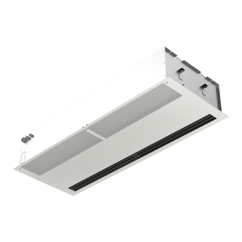
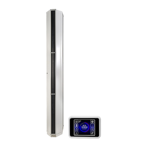
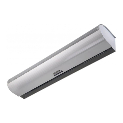
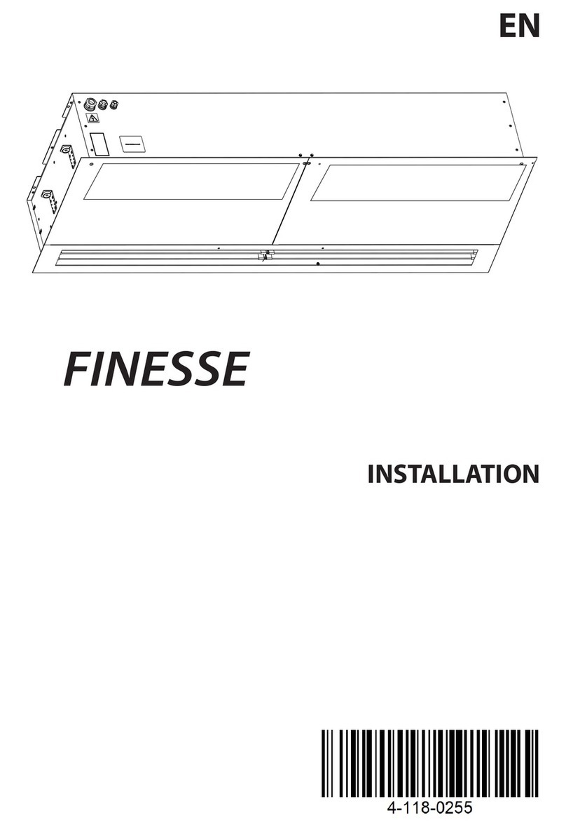
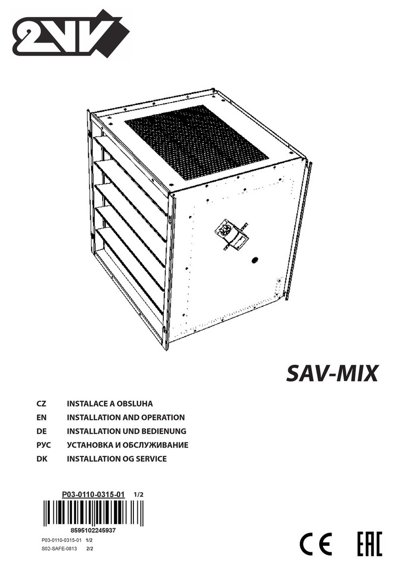
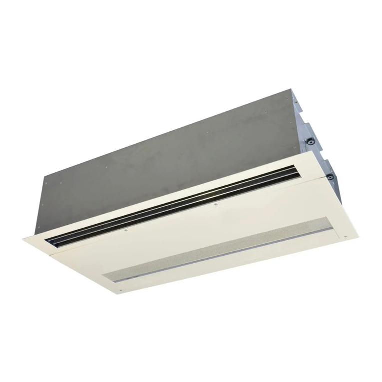
2VV BASIC Series User manual

AIR CURTAINS
LUFTSCHLEIER
19

electric wire heater / Elektroheizung
BASIC | VCB AIR CURTAINS
LUFTSCHLEIER
20
GRUNDEIGENSCHAFTEN
– In Längen von 60 und 90 cm lieferbar
– Luftstrom bis zu 475 m3/h
– FACE 2 in 1 – Ansauggitter + Filter = 2 in 1
– Vollkommen leiser Betrieb
– Schnelles Anlassen des Heizausgangs
– Einfache und intuitive Bedienung
– Einfache Montage
– Farbe im Standard RAL 9010 (Farbliche Ausführung des
Luftschleiers je nach Kundenwunsch)
Ein Fenster-Luftschleier und Tür-Lufterhitzer für kleinere Räume
mit Anwendung in Imbiss-Ständen, Drive-In-Restaurants,
Tankstellen und Pförtnerhäuschen, mit empfohlener Ins-
tallationshöhe bis zu 1,5 Metern*.
* Maximal empfohlene Installationshöhe, die für die meisten Andwen-
dugen geeignet ist (kann in Abhängigkeit von den am Installatiobsort
vorhabdenen Bedingungen abweichen)
BASIC FEATURES
– Lengths 60 and 90 cm available
– Air ow up to 475 m3/h
– FACE 2 in 1 – suction grille + lter = 2 in 1
– Silent operation
– Fast starting of heating output
– Simple and intuitive control
– Easy installation
– Standard colour RAL 9010 (any RAL – based colours may
be provided on customer’s request)
The air curtain for small openings where a narrow hot stream
is required for use in premises such as fast-food facilities,
drive-in restaurants, petrol stations and receptions with
a recommended height up to 1.5 m*.
* Maximum recommended installation height suitable for the most application
(may dier based on the existing conditions at the installation location)
PRIMARY PARAMETERS
Air curtain is designed for performance in an inner dry envi-
ronment with the outside
temperature between +5 °C to +40 °C and relative humidity
up to 80 %, for transferring air without gross dust, greasiness,
chemical vapours and other kinds of pollution. Electrical pro-
tection of this product is IP 20.
BASIC air curtains are equipped with electric wire heater with
automatic termostat on each element. Whole product is secured
by emergency thermostat with manual reset.
PRIMÄRE PARAMETER
Luftschleier ist für die Anwendung in einem trocknen Innenraum
mit einer Außentemperatur
zwischen +5°C und +40°C und einer relativen Luftfeuchtigkeit
bis zu 80% für die Übertragung von Luft ohne viel Staub, Fett,
chemische Dämpfe und andere Arten von Verunreinigungen
gebaut. Der elektrische Schutz dieses Produkts ist IP20.
BASIC sind mit Elektrokabel-Erhitzer mit automatischem Ther-
mostat an jedem Element ausgestattet. Das gesamte Produkt
ist durch einen Notthermostat mit manueller Rücksetzung
ausgestattet.

BASIC | VCB
AIR CURTAINS
LUFTSCHLEIER
21
Air curtain type
Luftschleiertyp
Airow volume
[m
3
/h]
Luftstromvolumen
[m
3
/h]
Acoustic
pressure
[dB(A)]*
Schalldruck
[dB(A)]*
Voltage /
Frequency
[V/Hz]
Spannung /
Frequenz
[V/Hz]
Fan
current
[A]
Ventila-
torstrom
[A]
Fan power
input [W]
Ventila-
torleis-
tungsauf-
nahme
[W]
Heater
power input
[kW]
Heizgerä-
teleistungs-
aufnahme
[kW]
Total
consump-
tion [A]
Gesamtver-
brauch [A]
Total pow-
er input
[kW]
Gesamt-
leistungs-
aufnahme
[kW]
Air
temper-
ature
increase
Δt [°C]
Lufttem-
peraturer-
höhung Δt
[°C]
Weight
[kg]
Gewicht
[kg]
max
speed
max.
Drehzahl
min
speed
min.
Drehzahl
3m 5m
VCB-A-060-E-RF-0-0 315 285 46,5 42,1 230 / 50 0,4 57,0 2,4 11 2,5 22,0 6
VCB-A-090-E-RF-0-0 475 410 48,5 44,0 230 / 50 0,7 87,0 3,1 14 3,2 19,0 8
* Schalldruckwerte bei 3 und 5 m Abstand für maximale Drehzahl.
Richtungsfaktor: Q=2.
* Acoustic pressure values at 3 and 5 m distance for maximum speed.
Directional factor: Q=2.
BASIC 600
ROZMĚRY BASIC 900
ROZMĚRY BASIC 600
161
190
152
176
30
70
612
10
3546
17,5 17,5
17,5
647
636
ROZMĚRY BASIC 900
ROZMĚRY BASIC 600
161
190
152
176
30
70
612
10
3546
17,5 17,5
17,5
647
636
BASIC 900

BASIC | VCB AIR CURTAINS
LUFTSCHLEIER
22
min 50 mm
min 150 mm
max 1800 mm
INSTALLATION UND MONTAGE
– Der Luftschleier kann nur in einer horizontalen Position
installiert werden.
– Der Luftschleier muss so nahe wie möglich an der Oberkante
einer Türönung angebracht werden. Siehe Abbildung.
– Um die beste Funktion des BASIC-Luftschleiers zu erreichen,
wird empfohlen, ein Modell zu benutzen, das etwas breiter
als die Önung ist, die verdeckt werden soll.
– Die richtige Arbeitsweise des Luftschleiers erfordert, dass die
vorgeschriebenen Abstände zu den umgebenden Objekten
eingehalten werden. Siehe Abbildung.
– Bei der Installation muss der Anschluss des Luftschleiers an
ein Elektrokabel berücksichtigt werden.
– Um Luftschleier aufzuhängen, sind die Halter, die der Lieferung
beigefügt sind, zu benutzen.
Das Projekt ist immer von einem HLK-Konstrukteur zu
entwickeln.
INSTALLATION AND ASSEMBLY
– Air curtain can be installed only in a horizontal position
– Air curtain must be placed as near the upper edge of a door
openning as possible, see the picture
– To achieve a best function of BASIC air curtain is recom-
mended to use model which is slightly wider than opening
which should be covered
– Correct operation of the air curtain requires that specied
distances from the surrounding objects are kept, see picture.
– When installing, it is necessary to consider the connection
of air curtain to an electrical lead
– To hang curtains, holders included in the delivery are used
Project shall always be developed by the HVAC designer.
STEUERUNG
BASIC-Luftschleier werden von einer drahtlosen Fernbedienung
aus gesteuert, die der Lieferung beigefügt ist. Die grundlegende
Charakteristik ist unten beschrieben.
CONTROL
BASIC air curtains are controlled by a wireless remote control,
which is included in the delivery. Basic characteristic of control
is described below.
max 1800 mm

BASIC | VCB
AIR CURTAINS
LUFTSCHLEIER
23
Overview of functions
Übersicht über die Funktionen
Type of controller
Typ des Reglers
Manual
Manuell
Regulation of air output
Regelung des Luftausgangs
2 speeds
2 Drehzahlen
Regulation of electric heater
Regelung des elektrisches Erhitzer
ON/OFF
ON/OFF
Possibility of connecting a door contact
Möglichkeit des Anschlusses eines Türkontakts
NO
NEIN
Temperature measurement
Temperaturmessung
NO
NEIN
External control
Externe Steuerung
NO
NEIN
Aftercooling electric air curtain
Nachkühlung des elektrisches Erhitzer
YES
JA
Pairing controller with more curtains
Pairing-Controller mit Luftschleier
YES*
JA*
Indication of selected function
Anzeige der ausgewählten Funktion
YES
JA
Nach dem Ausschalten des Luftschleiers wird eine automatische
Funktion für das sichere Abkühlen des Luftschleiers eingestellt,
und die Ventilatoren laufen für weitere 30 Sekunden. Diese
Funktion wird durch eine blinkende LED signalisiert, die sich
auf der Abdeckung des Luftschleiers bendet.
ZUBEHÖR
Es ist kein spezielles Zubehör erforderlich, um die richtige
Arbeitsweise der BASIC-Luftschleier zu gewährleisten.
SCHALTPLÄNE
Der BASIC-Luftschleier ist mit einem Netzkabel und einem
Stecker ausgestattet (3 m lang).
After turning air curtain o an automatic function for safe cool-
ing of the air curtain is set on and ventilators run for another
30 seconds. This function is signalized by a blinking LED placed
on the cover of the curtain.
ACCESSORIES
No special accessories is required to ensure a proper operation
of the BASIC air curtains.
WIRING DIAGRAMS
BASIC air curtain is supplied with a power cord including
a plug (3 m long).
* – One control panel can be paired (via radio frequency) with up to 60 curtains.
– Mit einzigem Bedienelement ist es durch Paarung möglich, bis zu 60 Geräten zu steuern.

BASIC | VCB AIR CURTAINS
LUFTSCHLEIER
24
SCHLÜSSEL DER CODIERUNG
VCB-A-060-E-RF-0-0
0– additional coding
0– standard white (RAL9010)
9– atyp RAL
RF – Radio frequency remote control
E– electric air curtain
060 – 060 – nominal width 600 mm
– 090 – nominal width 900 mm
A– economic series
VCB – air curtain BASIC
VCB-A-060-E-RF-0-0
0– zusätzliche Codierung
0– Standard weiß (RAL9010)
9– atyp RAL
RF – Funkfernbedienung
E– elektrischer Luftschleier
060 – 060 – Nennbreite 600 mm
– 090 – Nennbreite 900 mm
A– Leistungsreihe
VCB – Luftschleier BASIC
KEY TO CODING

air-only / Wärmetauscher
water heater / Wasserwärmetauscher
electric wire heater / Elektroheizung
ESSENSSE | VCE
AIR CURTAINS
LUFTSCHLEIER
25
BASISMERKMALE
– Ausführungen in den Längen 1, 1,5 und 2 m
– Luftleistung bis zu 4700 m3/h
– Straw System – Maximierung des Abschirmungseekts
– Face 2in1 – Ansauggitter + Filter = 2 in 1
– Integriertes Modul-Regelsystem (RF, SM, DM)
– Niedrige Einbauhöhe
– Farbe im Standard RAL 9010 (Farbliche Ausführung des
Luftschleiers je nach Kundenwunsch)
ESSENSSE
Luftschleier für Anwendung in Geschäftsräumen, Restau-
rants, Geschäftszentren, administrativen Gebäuden und
Produktionshallen, geeignet für Installationshöhe bis zu 4 m.
Der Luftschleier ist zum Betreib in innerer, trockener Umgebung
mit einer Umlufttemperatur zwischen 0 °C bis +40 °C, mit
relativer Feuchtigkeit von 80 % und zum Transport staubloser,
fettloser Luft, die auch keine chemischen Dämpfe oder sonstige
Verunreinigungen enthält vorgesehen. Der Luftschleier hat die
elektrische Schutzart IP 20. Den Entwurf des Luftschleiers hat
stets der Projektant von der Lufttechnik und Heizung zu lösen.
BASIC FEATURES
– Lengths: 1; 1.5 and 2 m
– Air ow up to 4700 m3/h
– Straw System – maximized screening eect
– FACE 2 in 1 – suction grille + lter = 2 in 1
– Universal interface for control module connection (RF, SM,
DM)
– Low build-in height
– Standard colour RAL 9010 (any RAL – based colours may be
provided on customer’s request)
ESSENSSE
Basic air curtain for use in a shops, shopping centres, res-
taurants, administrative buildings and manufacturing
halls with a recommended installation height up to 4 m.
The air curtain shall be installed indoor in a dry area with ambi-
ent temperatures ranging from 0 °C up to +40 °C and relative
humidity of up to 80 %. It is designed for conveying air free
of ne dust, grease, chemical fumes, and other impurities. IP
rating of the air curtain is IP 20. The air curtain project shall
always be developed by the HVAC designer.
S
T
R
A
W
S
Y
S
T
E
M

ESSENSSE | VCE AIR CURTAINS
LUFTSCHLEIER
26
PRIMARY PARAMETERS
Air curtains with electric heater are tted with automatic heat
thermostat and emergency thermostat with manual reset. The
warm-water exchangers are designed for the maximum oper-
ating water temperature of +100 °C and maximum operating
pressure of 1.6 MPa.
WICHTIGSTE PARAMETER
Die Luftschleier mit Elektrowärmetauscher sind mit einem Ha-
variethermostat mit manuellem Reset versehen. Die Warmwas-
serwärmetauscher sind für eine max. Betriebs-temperatur des
Wassers +100 °C und max. Betriebsdruck 1,6 MPa bestimmt.
* Stromreichweite bei Absenkung seiner Mittelgeschwindigkeit auf
3 m/s. Gilt für den Spitzenleistungstyp bei optimalen Bedingun-
gen (ISO 27327-1).
** Schalldruck, gemessen in 3 und 5 m Entfernung vom Gerät bei
maximaler Motorgeschwindigkeit. Richtungskoezient Q: 2.
*** Temperatur der angesaugten Luft +18°C bei maximaler Heizstu-
fe und höchster Ventilatorgeschwindigkeit.
**** Gewicht ohne Reglung.
VCE-A
Type
Typ
Recom-
mended
installation
height
[m]*
Empfohlene
Installa-
tionshöhe
[m]*
Air output
[m
3
/h]
Luftausstoß
[m
3
/h]
Acoustic pressure
[dB(A)]**
Schalldruck
[dB(A)]**
Heater pow-
er output
[kW]
Ausgangslei-
tung Heizge-
rät [kW]
Total con-
sumption
[V/A]
Gesamtver-
brauch
[V/A]
Motor
con-
sumption
[V/A]
Motorver-
brauch
[V/A]
Tem-
perature
increase Δt
[°C]***
Temperatu
ranstieg
Δt [°C]***
Frequency
[Hz]
Frequenz der
Stromversor-
gung
[Hz]
Weight
[kg]****
Gewicht
[kg]****
Speed 3
Ge-
schwin-
digkeit
3
Speed 2
Ge-
schwin-
digkeit
2
Speed 1
Ge-
schwin-
digkeit
1
3m 5m 1st
level
1 St.
2nd
level
2 St.
VCE-A-100-E-...
2,2
1000 880 760 48,5 44,0 2,4 4,7 400/7,1 230/0,3 14 50 15
VCE-A-150-E-... 1450 1330 1170 50,3 45,9 3,8 7,6 400/11,4 230/0,4 15 50 20
VCE-A-200-E-... 2000 1730 1460 50,9 46,5 4,8 9,5 400/14,1 230/0,5 14 50 25
VCE-A-100-S-... 1000 890 770 48,5 44,0 - - 230/0,3 230/0,3 - 50 14
VCE-A-150-S-... 1500 1360 1190 50,3 45,9 - - 230/0,4 230/0,4 - 50 18
VCE-A-200-S-... 2050 1770 1500 50,9 46,5 - - 230/0,5 230/0,5 - 50 23
VCE-A-100-G-... 1000 880 760 48,5 44,0 2,4 400/6,1 230/0,3 7 50 15
VCE-A-150-G-... 1450 1330 1170 50,3 45,9 2,0 4,8 400/8,4 230/0,4 10 50 20
VCE-A-200-G-... 2000 1730 1460 50,9 46,5 2,4 5,9 400/10,3 230/0,5 9 50 25
* Limited distance when air ow speed decreases to app. 3 m/s.
Applies to the highest capacity type under optimal conditions
(ISO 27327-1).
** Acoustic pressure measured at 3 and 5 m away from the device
at maximum motor speed. Direction coecient Q: 2.
*** Suction air temperature +18°C, at maximum heating level and
highest fan speed.
**** Weight without regulation.
* Stromreichweite bei Absenkung seiner Mittelgeschwindigkeit auf
3 m/s. Gilt für den Spitzenleistungstyp bei optimalen Bedingun-
gen (ISO 27327-1).
** Schalldruck, gemessen in 3 und 5 m Entfernung vom Gerät bei
maximaler Motorgeschwindigkeit. Richtungskoezient Q: 2.
*** Temperatur der angesaugten Luft +18°C bei maximaler Heizstu-
fe (90/70) und höchster Ventilatorgeschwindigkeit.
**** Gewicht ohne Reglung.
VCE-B
Type
Typ
Recom-
mended
installation
height
[m]*
Empfohlene
Installa-
tionshöhe
[m]*
Air output
[m
3
/h]
Luftausstoß
[m
3
/h]
Acoustic pressure
[dB(A)]**
Schalldruck
[dB(A)]**
Heater pow-
er output
[kW]
Ausgangslei-
tung Heizge-
rät [kW]
Total con-
sumption
[V/A]
Gesamtver-
brauch
[V/A]
Motor
con-
sumption
[V/A]
Motorver-
brauch
[V/A]
Tempera-
ture
increase Δt
[°C]***
Temperatu
ranstieg
Δt [°C]***
Frequency
[Hz]
Frequenz der
Stromversor-
gung
[Hz]
Weight
[kg]****
Gewicht
[kg]****
Speed 3
Ge-
schwin-
digkeit
3
Speed 2
Ge-
schwin-
digkeit
2
Speed 1
Ge-
schwin-
digkeit
1
3m 5m 1st
level
1 St.
2nd
level
2 St.
VCE-B-100-E-...
3
1450 1320 1120 55,9 51,5 2,4 5,9 400/10,2 230/0,6 12 50 16
VCE-B-150-E-... 2150 1860 1500 57,0 52,6 4,9 10,0 400/15,9 230/0,7 15 50 22
VCE-B-200-E-... 2800 2260 1770 57,5 53,0 6,0 12,5 400/19,6 230/0,8 14 50 27
VCE-B-100-V-... 1300 1190 1010 55,8 51,3 9,6 230/0,6 230/0,6 24 50 17
VCE-B-150-V-... 1900 1720 1410 54,4 49,9 15,7 230/0,7 230/0,7 26 50 23
VCE-B-200-V-... 2550 2160 1730 54,1 49,7 22,4 230/0,8 230/0,8 27 50 28
VCE-B-100-S-... 1500 1340 1140 56,5 52,0 - - 230/0,6 230/0,6 - 50 15
VCE-B-150-S-... 2200 1880 1530 58,6 54,2 - - 230/0,7 230/0,7 - 50 20
VCE-B-200-S-... 2900 2290 1800 57,7 53,2 - - 230/0,8 230/0,8 - 50 24
VCE-B-100-F-... 1450 1320 1120 55,9 51,5 4,7 9,4 400/14,0 230/0,6 21 50 16
VCE-B-150-F-... 2150 1860 1500 57,0 52,6 7,6 15,1 400/22,8 230/0,7 22 50 22
VCE-B-200-F-... 2800 2260 1770 57,5 53,0 9,6 19,1 400/28,3 230/0,8 20 50 27
VCE-B-100-G-... 1450 1320 1120 55,9 51,5 2,4 4,7 400/ 7,4 230/0,6 10 50 16
VCE-B-150-G-... 2150 1860 1500 57,0 52,6 3,8 7,6 400/11,6 230/0,7 11 50 22
VCE-B-200-G-... 2800 2260 1770 57,5 53,0 4,9 9,6 400/14,6 230/0,8 10 50 27
* Limited distance when air ow speed decreases to app. 3 m/s.
Applies to the highest capacity type under optimal conditions
(ISO 27327-1).
** Acoustic pressure measured at 3 and 5 m away from the device
at maximum motor speed. Direction coecient Q: 2.
*** Suction air temperature +18°C, at maximum heating level
(90/70) and highest fan speed.
**** Weight without regulation.

ESSENSSE | VCE
AIR CURTAINS
LUFTSCHLEIER
27
* Stromreichweite bei Absenkung seiner Mittelgeschwindigkeit auf
3 m/s. Gilt für den Spitzenleistungstyp bei optimalen Bedingun-
gen (ISO 27327-1).
** Schalldruck, gemessen in 3 und 5 m Entfernung vom Gerät bei
maximaler Motorgeschwindigkeit. Richtungskoezient Q: 2.
*** Temperatur der angesaugten Luft +18°C bei maximaler Heizstu-
fe (90/70) und höchster Ventilatorgeschwindigkeit.
**** Gewicht ohne Reglung.
VCE-C
Type
Typ
Recom-
mended
installation
height
[m]*
Empfohlene
Installa-
tionshöhe
[m]*
Air output
[m
3
/h]
Luftausstoß
[m
3
/h]
Acoustic pressure
[dB(A)]**
Schalldruck
[dB(A)]**
Heater pow-
er output
[kW]
Ausgangslei-
tung Heizge-
rät [kW]
Total con-
sumption
[V/A]
Gesamtver-
brauch
[V/A]
Motor
con-
sumption
[V/A]
Motorver-
brauch
[V/A]
Tempera-
ture
increase Δt
[°C]***
Temperatu
ranstieg
Δt [°C]***
Frequency
[Hz]
Frequenz der
Stromversor-
gung
[Hz]
Weight
[kg]****
Gewicht
[kg]****
Speed 3
Ge-
schwin-
digkeit
3
Speed 2
Ge-
schwin-
digkeit
2
Speed 1
Ge-
schwin-
digkeit
1
3m 5m 1st
level
1 St.
2nd
level
2 St.
VCE-C-100-E-...
4
2500 2250 1700 65,5 61,1 5,0 9,9 400/15,7 230/1,3 12 50 23
VCE-C-150-E-... 3600 3250 2700 66,2 61,7 7,9 15,2 400/23,8 230/1,7 13 50 32
VCE-C-200-E-... 4550 4000 3400 65,0 60,6 10,2 19,1 400/30,9 230/3,1 13 50 39
VCE-C-100-V-... 2150 1850 1500 65,1 60,6 17,2 230/1,0 230/1,0 24 50 25
VCE-C-150-V-... 3000 2700 2300 62,4 58,0 25,6 230/1,4 230/1,8 25 50 33
VCE-C-200-V-... 4250 3800 3050 64,4 59,9 37,0 230/3,1 230/3,1 24 50 42
VCE-C-100-S-... 2500 2250 1700 65,5 61,1 - - 230/1,3 230/1,3 - 50 22
VCE-C-150-S-... 3800 3400 2750 66,2 61,7 - - 230/1,7 230/2,1 - 50 30
VCE-C-200-S-... 4700 4050 3400 65,0 60,6 - - 230/3,1 230/3,1 - 50 37
VCE-C-100-G-... 2500 2250 1700 65,5 61,1 2,5 6,1 400/10,9 230/1,3 7 50 23
VCE-C-150-G-... 3600 3250 2700 66,2 61,7 4,8 9,8 400/15,6 230/1,7 8 50 32
VCE-C-200-G-... 4550 4000 3400 65,0 60,6 6,7 13,0 400/22,2 230/3,1 9 50 39
* Limited distance when air ow speed decreases to app. 3 m/s.
Applies to the highest capacity type under optimal conditions
(ISO 27327-1).
** Acoustic pressure measured at 3 and 5 m away from the device
at maximum motor speed. Direction coecient Q: 2.
*** Suction air temperature +18°C, at maximum heating level
(90/70) and highest fan speed.
**** Weight without regulation.
Type
Typ
Air
output
[m
3
/h]
Luftaus-
stoß
[m
3
/h]
Heating
output
[kW]
Heizaus-
toß
[kW]
Temperature
at exhaust
[°C]
Temperatur an
Abluftönung
[°C]
Pressure
loss
[kPa]
Druckver-
lust
[kPa]
VCE-B-100-V-... 1300 9,6 42,3 0,5
VCE-B-150-V-... 1900 15,7 44,9 2,6
VCE-B-200-V-... 2550 22,4 46,6 3,2
VCE-C-100-V-... 2150 17,2 42,0 2,5
VCE-C-150-V-... 3000 25,6 43,6 19,2
VCE-C-200-V-... 4250 37,0 44,1 13,8
Type
Typ
Air
output
[m
3
/h]
Luftaus-
stoß
[m
3
/h]
Heating
output
[kW]
Heizaus-
toß
[kW]
Temperature
at exhaust
[°C]
Temperatur an
Abluftönung
[°C]
Pressure
loss
[kPa]
Druckver-
lust
[kPa]
VCE-B-100-V-... 1300 6,3 33,6 0,2
VCE-B-150-V-... 1900 10,3 35,2 1,5
VCE-B-200-V-... 2550 14,8 36,4 1,4
VCE-C-100-V-... 2150 11,2 33,6 1,2
VCE-C-150-V-... 3000 16,7 34,7 9,2
VCE-C-200-V-... 4250 24,0 35,0 6,7
Type
Typ
Air
output
[m
3
/h]
Luftaus-
stoß
[m
3
/h]
Heating
output
[kW]
Heizaus-
toß
[kW]
Temperature
at exhaust
[°C]
Temperatur an
Abluftönung
[°C]
Pressure
loss
[kPa]
Druckver-
lust
[kPa]
VCE-B-100-V-... 1300 8,0 37,9 0,4
VCE-B-150-V-... 1900 13,0 40,0 2,0
VCE-B-200-V-... 2550 18,6 41,4 2,2
VCE-C-100-V-... 2150 14,1 37,7 1,8
VCE-C-150-V-... 3000 21,0 39,0 13,7
VCE-C-200-V-... 4250 30,4 39,4 9,9
Type
Typ
Air
output
[m
3
/h]
Luftaus-
stoß
[m
3
/h]
Heating
output
[kW]
Heizaus-
toß
[kW]
Temperature
at exhaust
[°C]
Temperatur an
Abluftönung
[°C]
Pressure
loss
[kPa]
Druckver-
lust
[kPa]
VCE-B-100-V-... 1300 4,7 29,5 0,2
VCE-B-150-V-... 1900 7,7 30,7 1,0
VCE-B-200-V-... 2550 12,2 31,5 0,8
VCE-C-100-V-... 2150 8,3 29,6 0,7
VCE-C-150-V-... 3000 12,4 30,4 5,6
VCE-C-200-V-... 4250 17,8 30,6 4,2
Water exchanger parameters for water temperature
gradient of 90/70 °C
Parameter des Wasserwärmetauschers bei
Wassertemperaturabsenkung 90/70 °C
Water exchanger parameters for water temperature
gradient of 70/50 °C
Parameter des Wasserwärmetauschers bei
Wassertemperaturabsenkung 70/50 °C
Water exchanger parameters for water temperature
gradient of 80/60 °C
Parameter des Wasserwärmetauschers bei
Wassertemperaturabsenkung 80/60 °C
Water exchanger parameters for water temperature
gradient of 60/40 °C
Parameter des Wasserwärmetauschers bei
Wassertemperaturabsenkung 60/40 °C
* Temperature of intake air: +18 °C / Ansauglufttemperatur + 18 °C

ESSENSSE | VCE AIR CURTAINS
LUFTSCHLEIER
28
HAUPTTEILE
1 Montagehalterungen (im Lieferumfang enthalten)
2Obere Abdeckung
3Bereich für den Anschluss des Reglungsmoduls
4Saugabdeckung
5Anschluss für den Wasserwärmeaustauscher (nur an
Wasserversionen)
6Seitenabdeckung (magnetisch befestigt)
1
2
3
4
5
6
MAIN PARTS
1 Mounting brackets (included in the delivery)
2Top cover
3Area for connecting the regulation module
4Suction cover
5Connection for water heat exchanger (only on water
versions)
6Side cover (attached magnetically)
AC
D
E
G
HI
F
=U
=
B
=NM=
=NM=
Air curtain dimensions
Abmessungen des Luftschleiers

ESSENSSE | VCE
AIR CURTAINS
LUFTSCHLEIER
29
Type
Typ A B C D E F G H I
VCE-A-100-X-... 834 1035 347 179 24 60 80 169 32
VCE-A-150-X-... 1334 1535 347 179 24 60 80 169 32
VCE-A-200-X-... 1834 2035 347 179 24 60 80 169 32
VCE-B-100-X-... 829 1030 381 189 29 80 80 163 38
VCE-B-150-X-... 1330 1530 381 189 29 80 80 163 38
VCE-B-200-X-... 1830 2030 381 189 29 80 80 163 38
VCE-C-100-X-... 835 1075 441 250 50 110 90 203 38
VCE-C-150-X-... 1337 1577 441 250 50 110 90 203 38
VCE-C-200-X-... 1837 2077 441 250 50 110 90 203 38
The tube diameters for connecting the water heat exchanger
are G1/2“ (VCE-C-... G3/4”).
Die Rohrdurchmesser für den Anschluss des Wasserwärme-
austauschers sind G1/2“ (VCE-C-... G3/4“).
INSTALLATION UND MONTAGE
– Der Luftschleier kann nur in horizontaler Lage installiert
werden
– Der Luftschleier ist allernächst zur oberen Kante der Türö-
nung anzubringen, in Abhängigkeit von Brandvorschriften in
gegebenem Land, siehe Abb.
– für die richtige Funktion wird empfohlen, der Luftschleier auf
jeder Seite um 100 breiter als die Türönung zu haben
– für die richtige Funktion des Luftschleiers sind die Abstands-
entfernungen des Luftschleiers, siehe Abbildung, zu beachten
– bei der Installation muss die Schaltung des Luftschleiers auf
die Warmwasser- und Stromzuführung berücksichtigt werden
– zum Anhängen des Luftschleiers werden Konsolen, die zu
der Lieferung gehören, benützt
INSTALLATION AND ASSEMBLY
– The air curtain shall be installed in a horizontal position only.
– The air curtain shall be located as close as possible to the
top edge of the doorway, minimal distance from the walls
depending on re safety and standards in the country, our
recommendation see gure.
– To ensure a correct function it is recommended that the air
curtain overlaps the doorway by 100 mm on both sides.
– Correct operation of the air curtain requires that specied
distances from the surrounding objects are observed, see
gure.
– Position of the heating water and power supply connections
shall be taken into consideration during installation.
– The air curtain shall be installed using supplied brackets.
89
6. INSTALLATION
6.3 AIR CURTAIN
INSTALLATION PROCEDURE:
1. Installation of the exible supply hose
- only on the water version
• It is recommended to use exible hoses for connecting the
water heater.
• The connection and pressure tests of the heater must be
carried out by a person qualied in the eld of plumbing,
who must at all times adhere to the valid norms and regu-
lations of the given country.
• The heater is designed to use water with a maximum pre-
ssure of 1.6 MPa and a maximum temperature of +100 °C.
2. Installation Procedure
1. screw out the screws of the bottom cover and remove the
cover
2. remove the side panel by pulling to the side
3. bend the metal sheet as shown in the picture; pull the
included water supply hoses through the created opening.
Connect the hoses and close the side cover.
• The minimum air curtain clearance distances must be ad-
hered to (see. picture - clearance distances) with respect to
the ammability of materials.
• The clearance distances with respect to the ammability
of materials is determined by the project engineer of the
given project, respecting the valid codes at the installation
location of the air curtain.
• The curtain can only be installed in a horizontal positi-
on.
• For the curtain to operate properly, there must be at least
200 mm of free space in front of the suction inlet cover.
• The exhaust of the curtain should be located as close as
possible to the door or curtained opening.
• the curtain should overlap the curtained opening on both
sides by at least 100mm.
• If you install the curtain above a door, locate it as close as
possible to the top edge of the door. Make sure that neither
the suction nor the exhaust is shielded by anything and
that the airow can travel freely into the room, see Picture.
min. 200 mm
min. 100 mm
min. 200 mm
min. 100 mm
min. 50 mm
DO NOT MISS!
* if the conditions require a greater foreblow than nor-
mal, then it is necessary to maintain a clearance of at
least 50 mm from the wall to enable movement.

ESSENSSE | VCE AIR CURTAINS
LUFTSCHLEIER
30
BEDIENUNG
Luftschleier Essensse werden mit Hilfe der Fernsteuerung,
gesteuert. Grundsätzliche Charakteristik der Steuerung ist in
der nachstehenden Tabelle angegeben.
LEISTUNGSREGLUNG DES WÄRMETAUSCHERS
Wir empfehlen folgende die Regulationsart:
1) grundlegende durch Drosseln
Thermostatventil TV-1-1/1. Das Ventil regelt kontinuierlich die
Zuleitung des Wärmetauschers in den Luftschleier in Abhän-
gigkeit von der Temperatur der aus dem Luftschleier bläst. Für
jeden Luftschleier ist ein Ventil zu benutzen.
2) wirtschaftliche durch Verteilen (auf/zu)
Dreiwegzonenventil ZV-3 mit einem Servoantrieb und
TER-P-Raumthermostat. Das Ventil schaltet die Zuleitung des
Wärmetauschers in den Luftschleier und zurück zur Wärmequelle
in Abhängigkeit von der Temperatur der aus dem Luftschleier
ausgeblasenen Luft und/oder der Raumtemperatur um. Für
jeden Luftschleier ist ein Ventil zu benutzen.
CONTROL
The Essensse air curtains are controlled by the remote control
panel or touch panel. The basic parameters of the controller
are given in table below.
WATER HEATER CONTROL
We recommend the following control methods:
1) Basic by throttling
TV-1-1/1 thermostatic valve. The valve controls smoothly the
warm water supply into the air curtain depending on the tem-
perature of air leaving the air curtain. One valve is required
for each air curtain.
2) Economical by splitting (open/closed)
ZV-3 three-way zone valve with a servo drive and TER-P room
thermostat. The valve switches the warm water supply into the
air curtain and back towards the heat source depending on the
temperature of air leaving the air curtain or depending on the
room temperature. One valve is required for each air curtain.

ESSENSSE | VCE
AIR CURTAINS
LUFTSCHLEIER
31
RGJ-VCE-RF-VS RGJ-VCE-RF-E RGJ-VCE-DM-S RGJ-VCE-DM-V
RGJ-VCE-DM-E RGJ-VCE-SM-E RGJ-VCE-SM-VS
Type of controller
Steuerungstyp
Manual
Manuell
Manual
Manuell
Manual
Manuell
Manual
Manuell
Manual
Manuell
Manual
Manuell
Regulation of air output
Steuerung der Luftleistung
2 speeds
2 Geschwindigkeiten
2 speeds
2 Geschwindigkeiten
3 speeds
3 Geschwindigkeiten
3 speeds
3 Geschwindigkeiten
3 speeds
3 Geschwindigkeiten
3 speeds
3 Geschwindigkeiten
Regulation of electric heater
Steuerung des
Elektrowärmetauschers
NO
NEIN
YES (ON/OFF)
JA (ON/OFF)
NO
NEIN
2 levels
2 Stufen
2 levels
2 Stufen
NO
NEIN
Regulation of water heater
Steuerung des
Wasserwärmetauschers
NO
NEIN
NO
NEIN
NO
NEIN
YES
JA
NO
NEIN
NO
NEIN
Possibility of connecting a
door contact
Türkontakt anschliessbar
YES
JA
YES
JA
YES
JA
YES
JA
YES
JA
YES
JA
Temperature measurement
Temperaturmessung
NO
NEIN
YES
(spatial thermostat)
JA
(Raumthermostat)
NO
NEIN
YES
(spatial thermostat)
JA
(Raumthermostat)
YES
(spatial thermostat)
JA
(Raumthermostat)
YES
(spatial thermostat)
JA
(Raumthermostat)
Aftercooling of the electric
heater Nachkühlen des
Elektrowärmetauschers
NO
NEIN
YES
JA
NO
NEIN
YES
JA
NO
NEIN
NO
NEIN
Chaining air curtains
Luftschleierverkettung
YES*
JA
YES*
JA
YES – max 6 pcs
JА – max 6 Stk.
NO
NEIN
NO
NEIN
Light indication of selected
function
Lichtanzeige der gewählten
Funktion
YES (on air curtain housing)
JA (auf dem Luftschleiergehäuse)
YES
JA
YES
JA
NO
NEIN
NO
NEIN
Controller connection to air
curtain
Verbindung des Steuergerätes
mit dem Luftchleier
RF signal
RF signal
RF signal
RF signal
Communication
cable
Kommunikations-
kabel
Communication
cable
Kommunikations-
kabel
Power cable (230 V)
with max. length of
100 m
Leistungskabel
(230 V) mit 100 m
max. Länge
Power cable (230 V)
with max. length of
100 m
Leistungskabel
(230 V) mit 100 m
max. Länge
OVERVIEW OF FUNCTIONS AND SENSOR
CONNECTION
ÜBERSICHT DER FUNKTIONEN UND
SENSORANSCHLÜSSE
* – One control panel can be paired (via radio frequency) with up to 60 curtains.
– Mit einzigem Bedienelement ist es durch Paarung möglich, bis zu 60 Geräten zu steuern.

ESSENSSE | VCE AIR CURTAINS
LUFTSCHLEIER
32
ZUBEHÖR
ERFORDERLICHES ZUBEHÖR
Dieses Zubehör muss bestellt werden, damit der Luftschleier
funktionsfähig ist.
Steuerungsmodul
Ein Steuerungsmodul ist ein obligatorisches Zubehörteil für den
Luftschleier ESSENSSE und muss für jeden Luftschleier bestellt
werden. Das Bedienfeld ist im Lieferumfang des Steuerungsmo-
dul enthalten. Die Bestellnummern für die Steuerungsmodule
sind weiter unten angegeben.
Die Bedienfelder der Steuerungsmodule RF werden über RF-si-
gnale gesteuert. DM-Modul Verwendung Kommunikation Kabel
mit RJ12-Stecker und PTPM.
Das Bedienfeld des SM-Steuerungsmoduls wird über ein
übliches Elektrokabel angeschlossen (Spannung 230 V). Die
geeignete Kabelgröße muss anhand der jeweiligen Installati-
onsbedingungen gewählt werden. Dieses Kabel muss von der
Firma geliefert werden, die die elektrische Installation des
Luftschleiers durchführt.
ACCESSORIES
REQUIRED ACCESSORIES
These accessories shall be ordered to make the air curtain
functional.
Control module
A control module is an required accessorie for ESSENSSE air
curtain and shall be ordered for each air curtain. Control panel
is included in delivery of control module. The ordering key for
control modules is provided below.
Control panels of RF control modules use RF signal communi-
cation. DM module uses communication cable with RJ12 and
PTPM connector.
Control panel of SM control module is connected using common
wiring cable (230 V control voltage). A suitable cross-section
of the cable shall be determined based on the particular instal-
lation conditions. This cable should be delivered by a company
performing the air curtain electrical wiring.
RGJ-VCE-DM-E
S– without heating regulation
(only for DM)
E– with electric heater regulation
V– with water heater regulation
(only for DM)
VS – without heating/water heater
(only for RF, SM)
RF – simple remote control
DM – digital manual control
SM – simple manual control
VCE – air curtain Essensse
RGJ – regulation
RGJ-VCE-DM-E
S – ohne Heizgerätregelung (nur DM)
E– mit Regelung von Elektro-
heizgeräten
V– mit Regelung von Wasser-
heizgeräten (nur DM)
VS – ohne Heizgerätregelung / mit
Wasserheizgeräten (nur RF, SM)
RF – einfache fern Steuerung
DM – digitale manuelle Steuerung
SM – einfache manuelle Steuerung
VCE – Luftschleier Essensse
RGJ – Regelung

ESSENSSE | VCE
AIR CURTAINS
LUFTSCHLEIER
33
Wegeventil mit Servoantrieb ZV-3
ZV-3
Turkontaktschalter
DS
Turkontaktschalter in einem Metallgehäuse fur
die DM-Regelung
DK-B-3
Raumthermostat
TER-P
Zeitschalter mit Wochenprogramm
SH-TM-848
Thermostatventil TV11/1
TV-1-1/1
OPTIONALES ZUBEHÖR
Weitere Details nden Sie auf der
entsprechenden Seite in diesem Katalog
Produced in EU
REGULATION РЕГУЛИРОВАНИЕ
The company reserves the right of change without previous announcement. ©2VV, spol. s r.o.
377
Your partner in ventilation...
ZV3
The ZV3 zone valve is designed for controlling the heat-
output of water-type heat exchangers. It is used especially
for controlling standalone water-type air heaters, heaters
inbuilt into the ventilation units, heaters in air curtains, and
so on.
The zone valve shall be installed in sheltered dry indoor
areas with the ambient temperature of +5 °C up to +60 °C.
Temperature of water being controlled shall range between
0 °C and +110 °C and pressure shall not exceed 1.0 MPa.
The zone valve is designed for controlling the heating water
in accordance with VDI 2035. Water being controlled shall
not contain any solid particles (sand, mud) or any
chemicals.
The electric IP rating of the zone valve is IP 40 (protection
against solid particles greater than 1 mm not protected
against water!).
The zone valve comprises a three-way valve and a servo
drive.
BASIC FEATURES
Зонный клапан ZV3 предназначен для регулирования
теплопроизводительности водяных теплообменников.
Используется, главным образом, для регулирования
отдельных водяных нагревателей воздуха, нагрева-
телей в составе вентиляционных установок, нагре-
вателей в составе воздушных завес и т.д.
Зонный клапан следует устанавливать в сухих,
закрытых помещениях с температурой воздуха от +5 °C
до +60 °C.
Температура воды, проходящей через клапан, должна
быть в пределах от 0 °C до +110 °C, а максимальное
давление 1,0 МПа
Зонный клапан предназначен для регулирования
отопительной воды по стандарту VDI 2035. Вода,
проходящая через клапан, не должна содержать
твердых частиц (песок, грязь) и каких-либо химикатов.
Электрическая защита зонного клапана с сервопри-
водом - IP 40 (защита от частиц >1 мм, нет защиты от
воды!)
Зонный клапан состоит из трехходового клапана и
сервопривода.
КРАТКАЯ ХАРАКТЕРИСТИКА
PRIMARY PARAMETERS ГЛАВНЫЕ ПАРАМЕТРЫ
The power cord length is 650 mm.
Длина соединительного кабеля 650 мм
ZV3
Type
Тип
DN 20
connection
size
присоединительный
размер
7
kvs
3
[m /h]
коэф. расхода клапана
3
k [м /ч]
vs
230
voltage
[V]
напряжение
[В]
4
power consumption
[W]
мощность
[Вт]
6
displacement time
[s]
время перемещения
[сек]
DN 20
A
90
94
B
90
130
94
Produced in EU
REGULATION РЕГУЛИРОВАНИЕ
The company reserves the right of change without previous announcement. ©2VV, spol. s r.o.
381
Your partner in ventilation...
TV1/1
The TV1/1 thermostatic valve is designed for controlling the
heat output of water exchangers through throttling. It is
used especially for controlling standalone water-type air
heaters, heaters inbuilt into the ventilation units, heaters in
air curtains, and so on.
The thermostatic valve shall be installed in sheltered dry
indoor areas with the ambient temperature of +5 °C up to
+60 °C.
Temperature of water being controlled shall range between
0 °C and +90 °C and pressure shall not exceed 0.1 MPa.
The thermostatic valve is designed for controlling the
heating water in accordance with VDI 2035. Water being
controlled shall not contain any solid particles (sand, mud)
or any chemicals.
The thermostatic valve comprises a fitting - DN25 (1“) and
thermostatic head with 2 m capillary.
BASIC FEATURES
Терморегулирующий клапан TV1/1 предназначен для
регулирования теплопроизводительности водяных
теплообменников путем дросселирования. Исполь-
зуется, главным образом, для регулирования отдельных
водяных нагревателей воздуха, нагревателей в составе
вентиляционных установок, нагревателей в составе
воздушных завес и т.д.
Терморегулирующий клапан следует устанавливать в
сухих, закрытых помещениях с температурой воздуха от
+5 °C до +60 °C.
Температура воды, проходящей через клапан, должна
быть в пределах от 0 °C до +90 °C, а максимальное
давление 0,1 МПа
Терморегулирующий клапан предназначен для
регулирования отопительной воды по стандарту VDI
2035. Вода, проходящая через клапан, не должна
содержать твердых частиц (песок, грязь) и каких-либо
химикатов.
Терморегулирующий клапан представляет собой
клапан DN25 (1“) с терморегулирующей головкой,
оснащенной капиллярной трубкой длиной 2 м
КРАТКАЯ ХАРАКТЕРИСТИКА
PRIMARY PARAMETERS ГЛАВНЫЕ ПАРАМЕТРЫ
145
R 1"
p
R 1"
G 1" 1/4
118
Your partner in ventilation...
Produced in EU
032
The company reserves the right of change without previous announcement. ©2VV, spol. s r.o.
AIR CURTAINS LUFTSCHLEIER
ECONOMIC-B Basic VCZ-02
ACCESSORIES ZUBEHÖR
Erforderliches Zubehör
Verbindungskabel
Die Steuerung wird an die Luftschleier mit der SM-
Steuerung mit einem üblichen Elektroinstallationskabel
(Steuerungsspannung 230 V) angeschlossen, siehe Kapitel
„Elektrische Schaltpläne“. Die günstigste Kabeldimension
muss laut konkreten Installationsbedingungen bestimmt
werden. Dieses Kabel muss die Firma, die die
Luftschleierinstallation anschließt, liefern.
Wählbares Zubehör
Thermostatventil
TV1-1/1 (nähere Beschreibung auf der Seite 399)
Dreiwegventil mit Servoantrieb
ZV-3 (nähere Beschreibung auf der Seite 395)
Required accessories
Connection cable
Controller for air curtains with the SM control is connected
using common wiring cable (230 V control voltage), see
“Wiring diagrams” chapter. A suitable cross-section of the
cable shall be determined based on the particular
installation conditions. This cable should be delivered
by a company performing the air curtain electrical
wiring.
Optional accessories
Thermostatic valve
TV1-1/1 (detailed description on the page
399)
Three-way valve with servo drive
ZV-3 (detailed description on the page 395)
Mischknoten
SMU-xx-xx (nähere Beschreibung auf der Seite 390)
WIRING DIAGRAMS
The recommended cross-section of the main power supply
cables is stated in the Instruction Manual.
All wiring diagrams provided in the technical catalog
are indicative only. When assembling the product,
observe strictly the nameplate ratings as well as
directions and diagrams affixed directly to the
product or enclosed to the product.
ELEKTRISCHE SCHALTPLÄNE
Empfohlene min. Dimensionierung der Leiter von der
Hauptzuleitung der el. Energie ist in der Anleitung
dargestellt.
Sämtliche, im Katalog angeführten, Schaltpläne sind
nur informativ. Bei der Montage des Produktes
richten Sie sich ausschließlich nach den Schild-
werten und Schaltbildern, die entweder auf dem
Produkt angebracht oder zum Produkt beigelegt
sind.
Mixing point
SMU-xx-xx (detailed description on the
page 390)
Door switch for air curtains fitted with the SM control
DS (detailed description on the page 428)
Turkontaktschalter fur die mit SM-gesteuerten
Luftschleiern
DS (nähere Beschreibung auf der Seite 428)
Door switch for air curtains fitted with
the RF control
DK-1 (detailed description on the page
411)
Turkontaktschalter fur die mit RF-gesteuerten
Luftschleiern
DK-1 (nähere Beschreibung auf der Seite 411)
Zone valve with servo drive ZV3
ZV-3
Door switch
DS
Door contact in a metal housing for air
curtains tted with DM control
DK-B-3
Room thermostat
TER-P
Timer with a weekly program
SH-TM-848
Thermostatic valve TV11/1
TV-1-1/1
OPTIONAL ACCESSORIES
More details can be found on the relevant
page in this catalog
Produced in EU
REGULATION REGULATION
The company reserves the right of change without previous announcement. ©2VV, spol. s r.o.
371
Your partner in ventilation...
RB
Servo drive
SERVO TD - 04 - 230 - 1 - necessary for
controlling the shutting flap. For more
details see page 430
Servo drive with emergency function
(reverse spring)
SERVO TDF - 08 - 230 - necessary for
controlling the shutting flap. The reverse
spring ensures closing the flap in case of
power supply failure. For more details see
page 432
Timer with a weekly program
SH-TM-848 - for more details see page 427
Servoantrieb
SERVO TD - 04 - 230 - 1 - erforderlich zum Bedienen der
Schließklappe. Nähere Beschreibung auf Seite 430
Servoantrieb mit Notfunktion (Rückstellfeder)
SERVO TDF - 08 - 230 - erforderlich zum Bedienen der
Schließklappe. Die Rückstellfeder stellt das Schliessen der
Klappe in dem Falle sicher, dass es zu einem Ausfall der el.
Energie kommt. Nähere Beschreibung auf Seite 432
Zeitschalter mit Wochenprogramm
SH-TM-848 - nähere Beschreibung auf Seite 427
Switching relay
RB-S - switching relay for controlling the shutting flap or
indicating the unit operation. The same relay connected in a
different way is used for controlling the zone valve when the
anti-freeze protection is activated. If
the shutting flap and anti-freeze
protection are connected, two relays
are required to ensure a correct
operation.
Anti-freeze protection sensor
PO - for more details see page 421
Schaltrelais
RB-S - Schaltrelais für die Betätigung der Schließklappe
oder Anzeige des Gerätelaufes. Das gleiche Relais in
anderem Anschluss wird zur Betätigung des Zonenventils
bei der Schaltung des Gegenfrostschutzes genützt. Sofern
die Schließklappe und der Gegenfrostschutz angeschlossen
sind, sind für die richtige Funktion zwei Relais erforderlich.
Frostschutzfühler
PO - nähere Beschreibung auf Seite 421
OPTIONAL ACCESSORIES
Communication cable for controller
The communication cable is designed for connecting the
DM module with controller using RJ12 and PTPM connector.
The standard length of the cable delivered with the air curtain
is 5 m. Other lengths are available based on the coding key
provided below.
KP-VCE10
05, 10, 20, 30 – cable length in m
Maximum cable length is 30m.
KP – Communication cable
OPTIONALES ZUBEHÖR
Kommunikationskabel
Die Kommunikationskabel sind in den Längen gemäß
der unten aufgeführten Bestellnummern erhältlich.
Als Standard wird es in der Länge von 5 m geliefert,
verketteten Luftschleier können nach dem Luftschleier
unten angeführten Schlüssel bestellt werden.
KP-VCE10
05, 10, 20, 30 – Kabellänge in m
Maximale Kabellänge ist 30m.
KP – Kommunikationskabel
Turkontaktschalter fur die DM-Regelung
DK-1
Your partner in ventilation...
Produced in EU
032
The company reserves the right of change without previous announcement. ©2VV, spol. s r.o.
AIR CURTAINS LUFTSCHLEIER
ECONOMIC-B Basic VCZ-02
ACCESSORIES ZUBEHÖR
Erforderliches Zubehör
Verbindungskabel
Die Steuerung wird an die Luftschleier mit der SM-
Steuerung mit einem üblichen Elektroinstallationskabel
(Steuerungsspannung 230 V) angeschlossen, siehe Kapitel
„Elektrische Schaltpläne“. Die günstigste Kabeldimension
muss laut konkreten Installationsbedingungen bestimmt
werden. Dieses Kabel muss die Firma, die die
Luftschleierinstallation anschließt, liefern.
Wählbares Zubehör
Thermostatventil
TV1-1/1 (nähere Beschreibung auf der Seite 399)
Dreiwegventil mit Servoantrieb
ZV-3 (nähere Beschreibung auf der Seite 395)
Required accessories
Connection cable
Controller for air curtains with the SM control is connected
using common wiring cable (230 V control voltage), see
“Wiring diagrams” chapter. A suitable cross-section of the
cable shall be determined based on the particular
installation conditions. This cable should be delivered
by a company performing the air curtain electrical
wiring.
Optional accessories
Thermostatic valve
TV1-1/1 (detailed description on the page
399)
Three-way valve with servo drive
ZV-3 (detailed description on the page 395)
Mischknoten
SMU-xx-xx (nähere Beschreibung auf der Seite 390)
WIRING DIAGRAMS
The recommended cross-section of the main power supply
cables is stated in the Instruction Manual.
All wiring diagrams provided in the technical catalog
are indicative only. When assembling the product,
observe strictly the nameplate ratings as well as
directions and diagrams affixed directly to the
product or enclosed to the product.
ELEKTRISCHE SCHALTPLÄNE
Empfohlene min. Dimensionierung der Leiter von der
Hauptzuleitung der el. Energie ist in der Anleitung
dargestellt.
Sämtliche, im Katalog angeführten, Schaltpläne sind
nur informativ. Bei der Montage des Produktes
richten Sie sich ausschließlich nach den Schild-
werten und Schaltbildern, die entweder auf dem
Produkt angebracht oder zum Produkt beigelegt
sind.
Mixing point
SMU-xx-xx (detailed description on the
page 390)
Door switch for air curtains fitted with the SM control
DS (detailed description on the page 428)
Turkontaktschalter fur die mit SM-gesteuerten
Luftschleiern
DS (nähere Beschreibung auf der Seite 428)
Door switch for air curtains fitted with
the RF control
DK-1 (detailed description on the page
411)
Turkontaktschalter fur die mit RF-gesteuerten
Luftschleiern
DK-1 (nähere Beschreibung auf der Seite 411)
Door switch for air curtains tted with DM
control
DK-1

ESSENSSE | VCE AIR CURTAINS
LUFTSCHLEIER
34
OPTIONALES ZUBEHÖR
Kommunikationskabel für die Verkettung
Die Kommunikationskabel sind in den Längen gemäß der
unten aufgeführten Bestellnummern erhältlich.
KABEL-05M
03, 05, 08, 10, 15, 20, 30, 40
– Kabellänge in m
Maximale Kabellänge ist 40 m.
KABEL – Kommunikationskabel
OPTIONAL ACCESSORIES
Communication cable for chaining
The communication cable is designed for chaining of other
air curtains controlled by DM regulation.
The lengths of communication cable are available according
the ordering key provided below.
KABEL-05M
03, 05, 08, 10, 15, 20, 30, 40
– cable length in m
Maximum cable length is 40 m.
KABEL – Communication cable
Optionales Zubehör
Kommunikationskabel
Das Kommunikationskabel dient zum Anschließen des DA-
Steuerungsmoduls an BMS (Modbus RTU).
Die Kommunikationskabel sind in den Längen gemäß der
unten aufgeführten Bestellnummern erhältlich.
KABEL-05M
03, 05, 08, 10, 15, 20, 30, 40
- Kabellänge in m
Maximale Kabellänge ist 50m.
KABEL - Kommunikationskabel
Thermostatventil TV1/1
Das Thermostatventil ist ein obligatorisches Zubehörteil für
das Steuerungsmodul VCS-R-SM-V.
TV1/1 (nähere Beschreibung auf Seite 326)
Wegeventil mit Servoantrieb ZV-3
Das Wegeventil ist ein obligatorisches Zubehörteil für das
Steuerungsmodul VCS-R-DM-V.
ZV-3 (nähere Beschreibung auf Seite 319)
Mischventil mit Servoantrieb MV-3
Das Mischventil ist ein obligatorisches Zubehörteil für das
Steuerungsmodul VCS-R-DA-V.
MV-3 (nähere Beschreibung auf Seite 323)
Optional accessories
Communication cable
The communication cable is designed for
connecting the DA control module to BMS
(Modbus RTU).
The lengths of communication cable are avail-
able according the ordering key provided below.
KABEL-05M
03, 05, 08, 10, 15, 20, 30, 40
- cable length in m
Maximum cable length is 50m.
KABEL - Communication cable
Thermostatic valve TV1/1
Thermostatic valve is an required accessorie
for VCS-R-SM-V control module.
TV1/1 (detailed description on the page
326)
Zone valve with servo drive ZV-3
Zone valve is an required accessorie for
VCS-R-DM-V control module.
ZV-3 (detailed description on the page 319)
Mixing valve with servo drive MV-3
Mixing valve is an required accessorie for
VCS-R-DA-V control module.
MV-3 (detailed description on the page 323)
STANDESSE Comfort VCS4
r
r
Your partner in ventilation...
048
Produced in EU The company reserves the right of change without previous announcement. ©2VV, spol. s r.o.
LUFTSCHLEIER AIR CURTAINS
SCHALTPLÄNE
Empfohlene min. Dimensionierung der Leiter von der Hauptzu-
leitung der el. Energie ist in der Anleitung dargestellt.
Sämtliche, im Katalog angeführten, Schaltpläne sind nur informativ.
Bei der Montage des Produktes richten Sie sich ausschließlich
nach den Schild-werten und Schaltbildern, die entweder auf
dem Produkt angebracht oder zum Produkt beigelegt sind.
WIRING DIAGRAMS
The recommended cross-section of the main power supply
cables is stated in the Instruction Manual.
All wiring diagrams provided in the technical catalog are indic-
ative only. When assembling the product, observe strictly the
nameplate ratings as well as directions and diagrams axed
directly to the product or enclosed to the product.
RGJ-VCE-RF-VS
RGJ-VCE-RF-VS VCE-XX-S(V)
OpenEnd Modul
OE-M-AC3
Steuermodul für BMS
OpenEnd module
OE-M-AC3
Control module for BMS

ESSENSSE | VCE
AIR CURTAINS
LUFTSCHLEIER
35
RGJ-VCE-RF-E
RGJ-VCE-RF-E VCE-xx-E(G,F)
RGJ-VCE-DM-S
RGJ-VCE-DM-S
Fuse
SH-TM-848
Control
Next unit
DK
VCE-xx-S
RGJ-VCE-DM-V
RGJ-VCE-DM-V VCE-xx-V
Fuse
TER-P
SH-TM-848
Control
Next unit
DK
4A
4A

ESSENSSE | VCE AIR CURTAINS
LUFTSCHLEIER
36
RGJ-VCE-DM-E
RGJ-VCE-DM-E VCE-xx-E(G,F)
Fuse
TER-P
SH-TM-848
Control
Next unit
DK
RGJ-VCE-SM-VS VCE-xx-S(V)
RGJ-VCE-SM-VS
ND-CM-SM-V-4
4A
RGJ-VCE-SM-E VCE-xx-E(G,F)
RGJ-VCE-SM-E
ND-CM-SM-E2-4
L3
L3 N
N
PE
PE
L2
L2
L1
L1DSDSThTh

ESSENSSE | VCE
AIR CURTAINS
LUFTSCHLEIER
37
KENNZEICHNUNGSSCHLÜSSELKEY TO CODING
0– 2VV version
9– Atyp RAL
0– Standard RAL
ZP – Regulation interface
E– Electric heater
V– Water heater
S– Air - only
F– Electric heater with increased
power
G– Electric heater with reduced
power
100 – Nominal width 1000 mm
150 – Nominal width 1500 mm
200 – Nominal width 2000 mm
A– Output series
B– Output series
C– Output series
VCE – Air Curtain ESSENSSE
VCE-B-100-E-ZP-0-0
0– 2VV Variante
9– Atyp RAL
0– Standard RAL
ZP – Verordnung Schnittstelle
E– Elektrowärmetauscher
V– Wasserwärmetauscher
S– ohne Wärmetauscher
F– Elektrowärmetauscher mit
erhöhter Leistung
G– Elektrowärmetauscher mit
Minderleistung
100 – Nominale Länge 1000 mm
150 – Nominale Länge 1500 mm
200 – Nominale Länge 2000 mm
A– Output-Serie
B– Output-Serie
C– Output-Serie
VCE – Luftschleier ESSENSSE
VCE-B-100-E-ZP-0-0

air-only / Wärmetauscher
water heater / Wasserwärmetauscher
electric wire heater / Elektroheizung
STANDESSE | VCS4 AIR CURTAINS
LUFTSCHLEIER
38
BASISMERKMALE
– Ausführungen in den Längen 1; 1.5; 2 und 2.5 m
– Luftleistung bis zu 6300 m3/h
– Niedriger Lärmpegel
– FACE 2 in 1 – Ansauggitter + Filter = 2 in 1
– Integriertes Modul-Regelsystem (SM, DM, DA)
– Einfache Installation und Service
– Möglichkeit der drahtlosen Funkfernbedienung
– Farbe im Standard RAL 9010 (Farbliche Ausführung des
Luftschleiers je nach Kundenwunsch)
STANDESSE ist ein außerordentlich leistungsfähiger und vom
Aussehen her ein sehr attraktiver Komfort-Luftschleier für die
Anwendung in Repräsentationsräumen, wie z. B. in Finanzhäu-
sern, Banken, Luxusläden, Einkaufszentren und Büroge-
bäuden mit empfohlener Installationshöhe bis zu 5 Metern.
Der Luftschleier ist zum Betrieb in Innenräumen, in trockener
Umgebung mit einer Umgebungstemperatur zwischen 0 °C und
+35 °C und einer relativen Feuchtigkeit bis 80 % vorgesehen.
Er ist zum Transport der Luft ohne groben Staub, Fette, chemi-
sche Dämpfe und sonstigen Verunreinigungen konzipiert. Der
Luftschleier mit montierter Frontabdeckung hat die Schutzart
IP 20. Das Luftschleierprojekt muss immer durch den
Klimatechniker entwickelt werden.
WICHTIGSTE PARAMETER
Die Luftschleier mit Elektrowärmetauscher sind mit einem Ha-
variethermostat mit manuellem Reset versehen. Die Warmwas-
serwärmetauscher sind für eine max. Betriebs-temperatur des
Wassers +100 °C und max. Betriebsdruck 1,6 MPa bestimmt.
BASIC FEATURES
– Lengths: 1; 1.5; 2 and 2.5 m
– Air ow up to 6,300 m3/h
– Very low noise level
– FACE 2 in 1 – suction grille + lter = 2 in 1
– Universal interface for control module connection (SM, DM,
DA)
– Easy installation and service
– Wireless control option
– Standard colour RAL 9010 (any RAL – based colours may
be provided on customer’s request
The STANDESSE is an extraordinary high-performance and
visually attractive comfortable air curtain for use in representative
premises, such as banks, luxury shops, shopping centres,
airports and administrative buildings with a recommended
installation height up to 5 m.
The air curtain shall be installed indoor in a dry area with ambi-
ent temperatures ranging from 0 °C up to +35 °C and relative
humidity of up to 80 %. It is designed for conveying air free
of rough dust, grease, chemical fumes, and other impurities.
IP rating of the air curtain is IP 20. The air curtain project
shall always be developed by the HVAC designer.
PRIMARY PARAMETERS
Air curtains with electric heater are tted with automatic heat
thermostat and emergency thermostat with manual reset. The
warm-water exchangers are designed for the maximum oper-
ating water temperature of +100 °C and maximum operating
pressure of 1.6 MPa.
This manual suits for next models
4
Table of contents
Other 2VV Heater manuals

2VV
2VV STANDESSE XP VCST5D150-V3 Series User manual

2VV
2VV VCB-A-060-E-RF-0-0 User manual

2VV
2VV VENESSE Comfort VCV-B-25E User manual

2VV
2VV FINESSE User manual

2VV
2VV ESSENSSE NEO VCES2-B-AC Series User manual

2VV
2VV Finesse EC Series User manual

2VV
2VV ESSENSSE NEO VCES3 AC Series User manual

2VV
2VV ESSENSSE NEO VCES2-B...E3 Series User manual

2VV
2VV VENESSE AirGenio control User manual

2VV
2VV VENESSE Comfort VCV Series User manual