Bentek Solar BTKv-D360 Series User manual

600V/1000V DC Combiner
Installation and Operating
Instructions
36-String Disconnect Models
Important Safety Instructions
Save These Instructions

© 2012, 2014 Bentek, Inc. All rights reserved.
No part of this publication (hardcopy or electronic form) may be reproduced or transmitted, in
any form or by any means, electronic, mechanical, photocopying, recording, or otherwise,
without the prior written consent of Bentek.
All trademarks are owned by their respective owners.
Specifications are subject to change without notice. Readers are cautioned that Bentek reserves
the right to make changes without notice. Bentek will not be responsible for any damages,
including indirect, incidental, or consequential damages, caused by reliance on the material
presented.
The terms and conditions governing the sale and licensing of Bentek Corp. products are set
forth in written agreements between Bentek and its customers. No representation or other
affirmation of fact contained in this publication shall be deemed to be a warranty or give rise to
any liability of Bentek whatsoever.
Bentek Corp. makes no warranty of any kind with regard to this material including, but not
limited to, the implied warranties of merchantability and fitness for a particular purpose.
Bentek Corp.
2350 Harris Way
San Jose, CA 95131
1-866-505-0303
1-408-954-9600
1-888-202-5009 (Support)
www.benteksolar.com
36-String Disconnect Models
600V/1000V DC Combiner Installation and Operating Instructions
Part 950-002305-000 Rev A
August 2014

600V/1000V DC Combiner Installation and Operating Instructions – 36-String Disconnect Models
950-002305-000 Rev A 3
Table of Contents
About This Book 5
Intended Audience . . . . . . . . . . . . . . . . . . . . . . . . . . . . . . . . . . . . . . . . . . . . . . . . . . . . 5
Notation Conventions. . . . . . . . . . . . . . . . . . . . . . . . . . . . . . . . . . . . . . . . . . . . . . . . . . 5
Manual Organization. . . . . . . . . . . . . . . . . . . . . . . . . . . . . . . . . . . . . . . . . . . . . . . . . . . 6
Document Revisions . . . . . . . . . . . . . . . . . . . . . . . . . . . . . . . . . . . . . . . . . . . . . . . . . . . 6
Chapter 1: Safety Instructions 7
Important Safety Instructions . . . . . . . . . . . . . . . . . . . . . . . . . . . . . . . . . . . . . . . . . . . 8
Information for Technicians . . . . . . . . . . . . . . . . . . . . . . . . . . . . . . . . . . . . . . . . . . . . . 9
Chapter 2: Product Description 11
Components . . . . . . . . . . . . . . . . . . . . . . . . . . . . . . . . . . . . . . . . . . . . . . . . . . . . . . . . . 12
Drawings of Components . . . . . . . . . . . . . . . . . . . . . . . . . . . . . . . . . . . . . . . . . . . 13
Specifications . . . . . . . . . . . . . . . . . . . . . . . . . . . . . . . . . . . . . . . . . . . . . . . . . . . . . . . . 15
Explanation of Symbols Used on Equipment . . . . . . . . . . . . . . . . . . . . . . . . . . . . . 16
Chapter 3: Installation Procedure 17
Required Tools and Materials . . . . . . . . . . . . . . . . . . . . . . . . . . . . . . . . . . . . . . . . . . 17
Summary Steps for Wall Mounting a Steel Enclosure . . . . . . . . . . . . . . . . . . . . . 18
Preparing to Install the Disconnect Combiner. . . . . . . . . . . . . . . . . . . . . . . . . . . . 19
Installing the Steel Enclosure . . . . . . . . . . . . . . . . . . . . . . . . . . . . . . . . . . . . . . . . 20
Installing the Fiberglass Enclosure . . . . . . . . . . . . . . . . . . . . . . . . . . . . . . . . . . . 22
Opening the Enclosure Door . . . . . . . . . . . . . . . . . . . . . . . . . . . . . . . . . . . . . . . . 25
Mounting the Disconnect Combiner . . . . . . . . . . . . . . . . . . . . . . . . . . . . . . . . . . . . 27
Preparing the Cutouts. . . . . . . . . . . . . . . . . . . . . . . . . . . . . . . . . . . . . . . . . . . . . . . . . 27
Cutouts for Steel Enclosures. . . . . . . . . . . . . . . . . . . . . . . . . . . . . . . . . . . . . . . . . 28
Cutouts for Fiberglass Enclosures . . . . . . . . . . . . . . . . . . . . . . . . . . . . . . . . . . . . 30
Connecting Wires. . . . . . . . . . . . . . . . . . . . . . . . . . . . . . . . . . . . . . . . . . . . . . . . . . . . . 32
Connecting Conductors from Source Circuits . . . . . . . . . . . . . . . . . . . . . . . . . 33
Attaching Conductors to the Recombiner or Inverter . . . . . . . . . . . . . . . . . . 33
Examples of Wiring . . . . . . . . . . . . . . . . . . . . . . . . . . . . . . . . . . . . . . . . . . . . . . . . . . . 34
Without Current Monitoring . . . . . . . . . . . . . . . . . . . . . . . . . . . . . . . . . . . . . . . . 34
With Current Monitoring . . . . . . . . . . . . . . . . . . . . . . . . . . . . . . . . . . . . . . . . . . . 35
Connecting the Current Monitoring System . . . . . . . . . . . . . . . . . . . . . . . . . . . . . 37
Finalizing the Installation . . . . . . . . . . . . . . . . . . . . . . . . . . . . . . . . . . . . . . . . . . . . . . 39
Preventive Maintenance . . . . . . . . . . . . . . . . . . . . . . . . . . . . . . . . . . . . . . . . . . . . . . . 40

600V/1000V DC Combiner Installation and Operating Instructions – 36-String Disconnect Models
950-002305-000 Rev A 4
Contents
600V/1000V DC Combiner Installation and Operating Instructions
950-002305-000 Rev A 5
About This Book
This manual provides information on installing the Bentek Disconnect Combiner.
Information is included on mounting the equipment on a prepared base and
connecting the wires to the proper locations.
Intended Audience
This manual is for those qualified to deal with the dangers and hazards involved
in installing electric devices. Those using this manual should be skilled in reading
site plans and electrical wiring schematics. Users should be familiar with meeting
requirements contained in UL 50, “Standard for Enclosures for Electrical
Equipment,” UL 514B, “Standard for Safety Conduit, Tubing and Cable Fittings,”
National Electrical Code, ANSI/NFPA 70, and other applicable standards
documents.
Notation Conventions
This manual uses the following notation conventions:
WARNINGWARNING
Warns you of something that could result in physical injury or death.
AVERTISSEMENT
Vous avertit de quelque chose qui pourrait avoir comme conséquence des
dommages corporels ou la mort.
CAUTIONCAUTION
Cautions you against anything that may damage equipment.
ATTENTION
Attentions vous contre tout ce qui peut endommager l'équipement.
600V/1000V DC Combiner Installation and Operating Instructions
950-002305-000 Rev A 6
About This Book
NOTE
Provides information of special interest or importance.
Manual Organization
This manual is organized as follows:
Chapter 1, “Safety Instructions,” provides information on warnings and
guidelines for installing the product safely.
Chapter 2, “Product Description,” describes the Combiner and provides
specifications.
Chapter 3, “Installation Procedure,” describes how to install the Combiner.
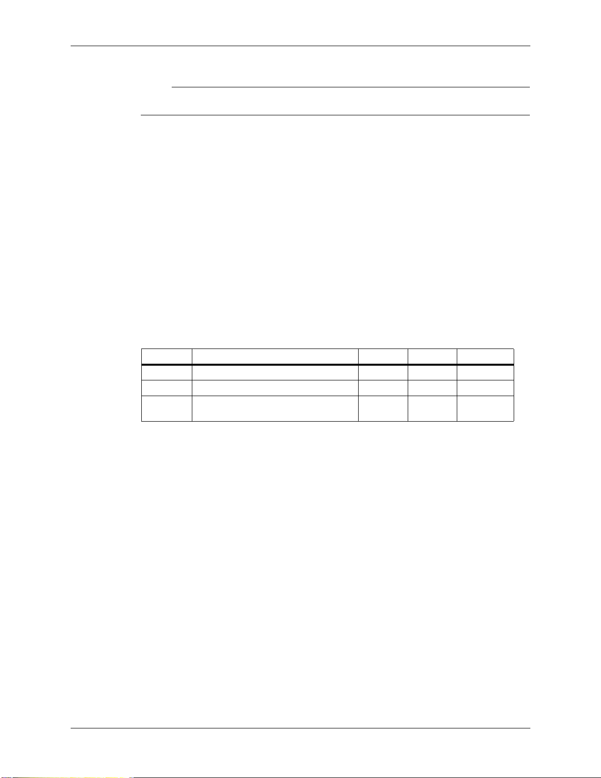
Document Revisions
Revision Description Date Author Approval
Z1 Initial release. 9/26/12 GLB MS
Z2 Add French warnings and cautions. 10/18/12 GLB CS
A Added installation guidelines and
corrected disconnect size. 8/12/14 GLB KJ
600V/1000V DC Combiner Installation and Operating Instructions
950-002305-000 Rev A 7
Chapter 1
Safety Instructions
This manual contains important safety instructions for the following Bentek
Combiner equipment:
In model numbers:
vspecifies the voltage (6=600 or 10=1000).
xx refers to the number of fuses (up to 36).
yy refers to the fuse rating.
zz refers to the type of enclosure (FB for fiberglass, SS for stainless steel, or
CS3 for NEMA-3R steel or CS4 for NEMA-3R/4 steel).
D specifies the amperage of the load-break disconnect unit.
S indicates the presence of the current monitoring system.
WARNINGWARNING
Disconnect all power prior to doing any work on this equipment.
AVERTISSEMENT
Déconnecter toute la puissance avant d'effectuer n'importe quel travail sur cet
équipement.
WARNINGWARNING
The installation, adjustment, or repair of Bentek Combiner equipment involves
risk of contact with potentially lethal voltages and currents. These servicing
instructions are for use by qualified personnel only. To reduce the risk of electric
shock, do not perform any servicing other than that specified in the operating
instructions unless you are qualified to do so.
There are no user-serviceable parts inside the Combiner equipment. Refer
servicing to qualified personnel.
The enclosure door should remain closed while the Combiner is operational.
Servicing or adjustments should not be performed while the circuits are
energized.
Model BTKv-xxyy-D360-zz Model BTKv-xxyy-D360-S-zz

600V/1000V DC Combiner Installation and Operating Instructions
950-002305-000 Rev A 8
Chapter 1: Safety Instructions
AVERTISSEMENT
L'installation, l'ajustement, ou la réparation de l'équipement de combinateur de
Bentek implique le risque de contact des tensions et des courants
potentiellement mortels. Ces instructions de service sont à l'usage du personnel
qualifié seulement. Pour réduire le risque de décharge électrique, ne pas assurer
l'entretien autre que celui spécifique dans les consignes d'utilisation à moins
que vous soyez qualifié faire ainsi.
Il n'y a aucune partie utilisateur-utile à l'intérieur de l'équipement de
combinateur. Se référer l'entretien au personnel qualifié.
La porte de clôture devrait rester fermée tandis que le combinateur est
opérationnel. L'entretien ou l'ajustement ne devrait pas être effectué tandis que
les circuits activent.
Important Safety Instructions
The following important safety instructions must be understood and followed.
Save these instructions.
Familiarize yourself with warning and hazard precautions for this combiner
so that the dangers of this device and its components are understood.
Mount the enclosure such that it is not rendered unapproachable for
inspection or safety needs.
Install the combiner enclosure so that it conforms to national and local safety
and operational codes (NEC and CSA).
The enclosure must only be opened and serviced by authorized and
knowledgeable service and/or contract personnel.
Read this manual and understand all safety, installation, and operational
information before opening or working on this device or any of its
connections or components.
If you have questions that are not answered in this document, contact Bentek
Support at 1-888-202-5009 or at www.benteksolar.com.
The following are NOT present in this equipment: Class 2 circuits, abnormal
tests, AC output, or battery circuits.
Torque tightening information is located on the mounting pan.

600V/1000V DC Combiner Installation and Operating Instructions
950-002305-000 Rev A 9
Chapter 1: Safety Instructions
Information for Technicians
It is your responsibility as the installation technician to follow these instructions
during installation and/or maintenance of Bentek Combiner equipment.
WARNINGWARNING
Risk of electrical shock exists from energy stored in the inverters. The inverters
contain energy storage devices that require 15 minutes in order to safely
discharge their lethal voltages after disconnecting all sources of supply.
AVERTISSEMENT
Le risque de décharge électrique existe de l'énergie stockée dans les inverseurs.
Les inverseurs contiennent les dispositifs de stockage de l'énergie qui ont besoin
de 15 minutes afin de décharger sans risque leurs tensions mortelles après
déconnexion de toutes les sources d'approvisionnement.
You are advised that:
You must reference the NFPA 70®Guide for safety precautions that should
be followed at electrical installations or sites.
Upon connection, this unit is under voltage. At this point, the equipment
contains lethal DC voltages.
When the photovoltaic (PV) array is exposed to light, it supplies lethal DC
voltage to this equipment.
As the installer, you must reference the National Electric Code (NEC) sections
250 and 690 to ensure proper system wiring and grounding compliance. In
addition, all state and federal Occupational Safety and Health Administration
(OSHA) guidelines and regulations must be followed.
Unless otherwise specified, wiring methods must be in accordance with the
National Electrical Code, ANSI/NFPA 70.
Installations in Canada shall be in accordance with the Canadian Electrical
Code, Part I.

600V/1000V DC Combiner Installation and Operating Instructions
950-002305-000 Rev A 10
Chapter 1: Safety Instructions
600V/1000V DC Combiner Installation and Operating Instructions – 36-String Disconnect Models
950-002305-000 Rev A 11
Chapter 2
Product Description
The DC Combiner combines multiple PV array source circuits into one or more
DC outputs. It commonly provides an interface to the recombiner or inverter.
The Disconnect models provide a load-break disconnect with the handle
installed on the door of the combiner.
The Combiner allows for safe operation of the system in the unlikely event that a
problem with a source circuit leads to abnormally high current. The Combiner
provides a convenient means of diagnosing the DC portion of a PV system for
routine maintenance and troubleshooting.
Each source circuit is protected separately from overcurrent limits through fuses
according to the requirements of the National Electric Code (NEC).
Fuses are available in several sizes to meet your needs.
Figure 1 Disconnect Combiner - front view
Disconnect
handle
Latch with cover
for padlock (or
Latch
optional key lock)

600V/1000V DC Combiner Installation and Operating Instructions – 36-String Disconnect Models
950-002305-000 Rev Z1 12
Chapter 2: Product Description
Components
The Disconnect Combiner is a wall-mounted NEMA-3R or wall/roof-mounted
NEMA-3R/4 electrical enclosure and contains the following components (see the
following figures):
Load-break Disconnect—360A disconnect unit that provides for load-break
isolation. The load-break disconnect device allows for safer replacement of
string fuses by providing a single handle isolation of the solar PV array from
the load. The handle is installed on the door.
Fuse Blocks—Fuse holders with 600VDC- or 1000VDC-rated fuses.
Plastic Shields—Plastic guards that increase safety by preventing
unintentional contact with live parts.
Ungrounded Busbar—Aluminum or copper bar used to combine all
ungrounded inputs.
Grounded Busbar—Aluminum bar used to combine all grounded inputs.
Equipment Ground Busbar—Aluminum bar used to combine individual
source circuit grounds to system ground.
Insulators—Plastic standoffs used to isolate the electricity between the
busbars and the metal backplane and enclosure.
Surge Protector (optional)—A UL1449-compliant surge protector provides
protection against damaging surges such as lightning strikes or static
discharges that PV installations may be vulnerable to.
Current monitoring system (optional)—Provides monitoring of performance
of each string from PV arrays.
NOTE
Bentek assemblies may use components that are silver plated. This plating may
oxidize (tarnish) over time as a result of natural exposure to standard
atmospheric conditions and become brownish, yellow, off-color or mottled in
appearance. This process is normal and should not be mistaken for indications of
over current. The oxidation of the silver plating will not affect the performance of
the assembly in any way.
600V/1000V DC Combiner Installation and Operating Instructions – 36-String Disconnect Models
950-002305-000 Rev Z1 13
Chapter 2: Product Description
Drawings of Components
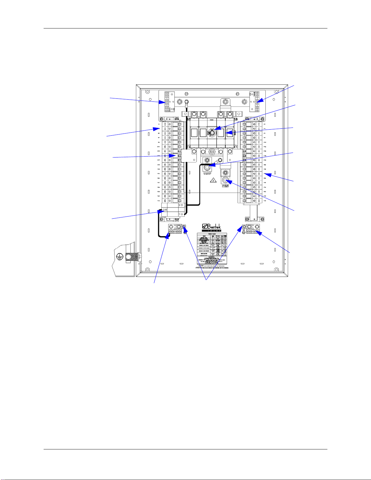
Figure 2 Disconnect Combiner - drawing of inside of 36-string combiner without
current monitoring
Ungrounded
input
terminals
Grounded
input
terminals
Disconnect
switch
Equipment ground
Optional
surge
suppressor
Fuse blocks
Equipment ground
input terminals
Ungrounded
output
Grounded
output terminal
output terminals
Load-break
disconnect
units
terminal
Equipment ground
input terminals
Grounded
input
terminals
Ungrounded
input
terminals
(optional)

600V/1000V DC Combiner Installation and Operating Instructions – 36-String Disconnect Models
950-002305-000 Rev Z1 14
Chapter 2: Product Description
Figure 3 Disconnect Combiner - drawing of inside of 36-string combiner with
Current Monitoring using 12-string monitors
The wiring shown in this drawing shows the factory-installed wiring to support
the current monitors and power supply as well as the surge protector. When
multiple current monitors are present, the daisy-chained wires are shown.
Ungrounded
input
terminals
Grounded
input
terminals
Disconnect
switch
Equipment ground
Optional
surge
suppressor
Fuse blocks Ungrounded
output
Grounded
output
input terminals
Load-break
disconnect
units
terminal
Current monitoring unit (3)
Current sensors
Power supply
Equipment ground
output terminal
terminal
Customer
connection
points
Equipment ground
input terminals
Grounded
input
terminals

600V/1000V DC Combiner Installation and Operating Instructions – 36-String Disconnect Models
950-002305-000 Rev Z1 15
Chapter 2: Product Description
Specifications
Table 1 through Table 5 show the specifications for the Disconnect Combiner.
In model numbers:
vspecifies the voltage (6=600 or 10=1000).
xx refers to the number of fuses (18 to 36).
yy refers to the fuse rating.
zz refers to the type of enclosure (FB for fiberglass, SS for stainless steel, or
CS3 for NEMA-3R steel or CS4 for NEMA-3R/4 steel).
D specifies the amperage of the load-break disconnect unit.
S indicates the presence of the current monitoring system.
Ta b l e 1 Electrical Specifications of Disconnect Combiner
Model
Max # of
Strings
(xx)
Max. Fuse
Capacity per
string (yy)
Continuous
Current
Rating (A)**
Max.
Voltage
(VDC)
BTKv-xxyy-D360-zz 36 20A 360 600 or
1000
BTKv-xxyy-D360-S-zz 36 20A 360
** Continuous Current Rating is determined by the bus configuration and/or the
main disconnect.
Ta b l e 2 Physical Specifications of Disconnect Combiner
Description Height* Width* Depth* Weight
up to 36 strings, without
current monitoring 30 inches 24 inches 8 inches
10 inches
(fiberglass)
90 lbs**
up to 36 strings, with current
monitoring 30 inches 30 inches 8 inches 100 lbs
* See Table 7 and Table 8 for exact dimensions of enclosures.
** Fiberglass enclosures are approximately 10 pounds lighter. Fiberglass enclosures are
not available for 36-string systems with Current Monitoring.
Ta b l e 3 Connector and Wire Information
Enclosure mounting bolt 5/16 inch or 8 mm
Output type 3/8 in. stud, CU/AL
Dual lug compatible (back-to-back) Yes
Output wire temp rating 90oC
Optional mechanical lugs Yes, CU/AL to 600MCM
Ungrounded input wire range 18-8AWG, CU
Ungrounded input wire temp rating 75oC
Grounded input wire range 14-4AWG, CU/AL
Grounded input wire temp rating 90oC
Grounded input number up to 36, > fuse count
Ground input wire range 14-4AWG, CU/AL

600V/1000V DC Combiner Installation and Operating Instructions – 36-String Disconnect Models
950-002305-000 Rev Z1 16
Chapter 2: Product Description
Explanation of Symbols Used on Equipment
The following symbols are used to identify parts and provide warnings for the
Combiner.
Ground input number 12
Ground output size 14-2/0 CU/AL
Auxiliary power input for current
monitoring 115-230VAC, <1A, 50/60Hz
Short circuit rating 10kAIC
Power supply 24VDC, 1A
Auxiliary power TB wire range for current
monitoring 20-8AWG (2x20-12 AWG), CU
Communication TB wire range (in and
out) for current monitoring 30-12AWG, CU
Ta b l e 4 Environmental Specifications of Combiner
Maximum operating altitude 2000 meters
Relative humidity 0-95%
Operating temperature range -20oC to +50oC
If operating temperatures or altitude exceed these specifications,
contact your Bentek representative to determine deratings.
Ta b l e 5 Certifications
ISO 9001:2008 Quality certified
TÜV SÜD Listed to UL1741 *
TÜV SÜD Listed to CSA22.2 No. 107.1 *
* Note: Combiners in fiberglass enclosures are not TÜV SÜD Listed.
Ta b l e 6 Symbols on Equipment
CAUTION: Risk of Electric Shock. Circuits are live. Disconnect
unit before servicing. Do not remove cover. No user
serviceable parts inside. Refer servicing to qualified service
personnel.
GROUND—This symbol identifies the equipment ground points.
DISCONNECT “ON”—This symbol identifies that the switch is in the
“on” position.
DISCONNECT “OFF”—This symbol identifies that the switch is in the
“off” position.
Ta b l e 3 Connector and Wire Information (Continued)

600V/1000V DC Combiner Installation and Operating Instructions – 36-String Disconnect Models
950-002305-000 Rev A 17
Chapter 3
Installation Procedure
This chapter describes the mounting and wiring or connections required to
install the Combiner.
Contact Bentek Support at 1-888-202-5009 for additional assistance.
Required Tools and Materials
Standard construction, electrical tools, basic electrical safety, and testing
instruments are required for the installation of the Combiner enclosure.
Additionally, the installation requires:
Calibrated torque wrench.
Personal protective equipment such as job-related clothing, electrical safety
gloves, safety goggles, etc.
Installers must reference the specific site scope and project drawings, including
the system layout and related electrical drawings, for additional information and
considerations.
CAUTIONCAUTION
The installer is responsible for verifying placement of internal components prior
to drilling holes and making any cutouts in the chassis.
ATTENTION
L'installateur est responsable de vérifier le placement des composants internes
avant les trous drilling et de faire tous les coupes-circuit dans le châssis.

600V/1000V DC Combiner Installation and Operating Instructions – 36-String Disconnect Models
950-002305-000 Rev A 18
Chapter 3: Installation Procedure
Summary Steps for Wall Mounting a Steel
Enclosure
This section is an example of how to prepare and mount a steel combiner
enclosure on a wall. All work must be performed and verified in accordance with
local codes. The procedures for installing steel enclosures are the same
regardless of the enclosure size. The exact measurements of the different sizes of
enclosures and distances between mounting holes are listed in Table 7.
Preinstallation
1. Verify that the hardware (5/16 inch bolts) to be used supports the weight of
the enclosure and is readily available in sufficient quantities to complete the
job.
2. Locate the mounting holes in each corner of the enclosure. Remove the
plastic plugs from each hole.
3. The wall where the enclosure will be mounted should have been marked off
and drilled. Appropriate mounting suspension hardware should have been
installed and secured. Holes matching the enclosure mounting pattern
should have also been drilled. Verify the location of all mounting hole
drilling.
Installation
1. Prepare the mounting hardware by stacking the washers and insulator
material on the bolts so that when the screw is mated to the mounting point
on the wall, the enclosure is brought back to its NEMA rating. Failure to do so
may allow the elements to enter the box and will void the warranty.
2. With the enclosure door closed, raise the enclosure to the point where it will
be mounted. Support the enclosure so it can be aligned to the mounting
holes in the support structure.
3. Open the enclosure door and position the enclosure so the mounting holes
are aligned with the holes that were predrilled in the wall. Insert a mounting
bolt into the mounting hole in the upper left corner. Screw the mounting
bolt into the hole until the head is 1/4 inch from being secure. Repeat for the
top right, bottom left, and bottom right mounting holes.
4. Starting with the top left mounting screw, tighten the screw until it is secure.
Moving clockwise, secure the remainder of the screws until the enclosure is
secured to the wall with no movement.
5. The enclosure mounting is complete. Notify the inspection team to verify the
mounting.

600V/1000V DC Combiner Installation and Operating Instructions – 36-String Disconnect Models
950-002305-000 Rev A 19
Chapter 3: Installation Procedure
Preparing to Install the Disconnect Combiner
Refer to the project drawings to identify the mounting location and any specific
location requirements or special instructions.
The mounting area must be at least as large as the enclosure to be mounted and
be able to support the weight of the equipment.
When wall or roof mounting the enclosure, it must be secured to a rigid
substrate, using appropriately sized hardware.
When mounting the enclosure horizontally, it is recommended that it be
mounted at an angle of at least 15 degrees to prevent water pooling on the
door.
The enclosure can be mounted vertically or at any angle in between fully
vertical (90 degrees) and horizontal.
When installing in climates with snowfall, the combiner must be mounted
vertically.
It is not recommended that it be mounted in any position such that the door
drops down when opened.

600V/1000V DC Combiner Installation and Operating Instructions – 36-String Disconnect Models
950-002305-000 Rev A 20
Chapter 3: Installation Procedure
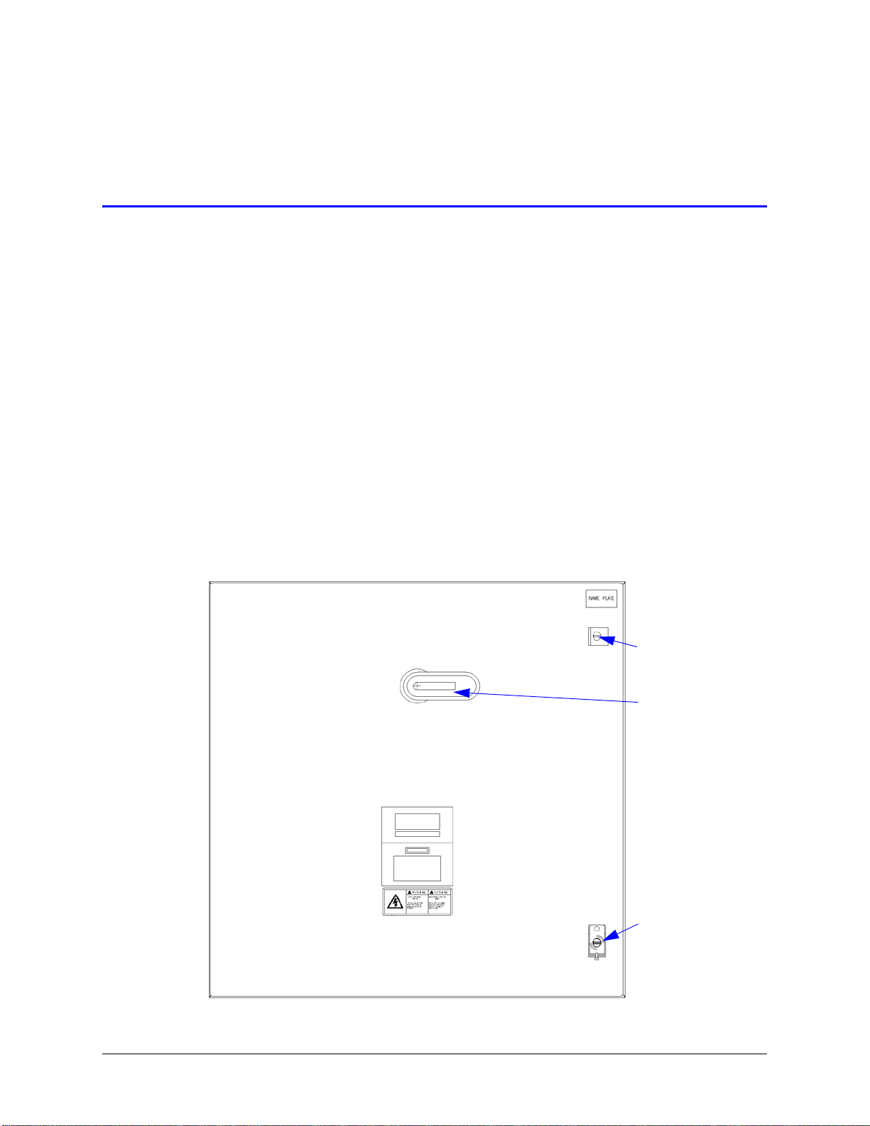
Installing the Steel Enclosure
Figure 4 provides a diagram of the enclosure, and Table 7 shows the values for
each of the measurements. The mounting holes are actually located in the back
panel of the enclosure. Use 5/16 inch or 8 mm bolts for mounting the enclosure.
Figure 4 The steel enclosure and mounting holes
This manual suits for next models
1
Table of contents
Popular Safety Equipment manuals by other brands


Assa Abloy
Assa Abloy Securitron EEB2 Installation & operating instructions

rba
rba STERI+SHIELD RBA490 Straight Series Installation, operation and maintenance instructions

Husqvarna
Husqvarna X-COM Active Operator's manual

Stahl
Stahl Ex e operating instructions

Petzl
Petzl VERTIGO WL TECHNICAL NOTICE

Guardian
Guardian CABLE CLIMBING SYSTEM instruction manual