Bentel Security BXM24 User manual


Descrizione
BXM24 e BXM12 sono due Stazioni di Alimen-
tazione studiate per l’integrazione della corren-
te fornita dalle centrali antincendio e antifurto
in impianti particolarmente esigenti.
Le Stazioni sono sostanzialmente simili: entram-
be sono costituite da un Modulo Alimentatore
che fornisce la tensione ridotta e raddrizzata a
partire dalla tensione di rete e da un’Elettronica
di Controllo alloggiati in un contenitore metallico
protetto contro i tentativi di sabotaggio in grado di
alloggiare un Accumulatore (due nel BXM24)
che garantisce l’alimentazione in caso di black-
out (mancanza della tensione d’ingresso).
La differenza fra i due modelli è rappresentata
dalla tensione di uscita che è 27,6 V per il
BXM24 (valore normalizzato per i sistemi an-
tincendio) e 13,8 V per il modello BXM12 (va-
lore normalizzato per i sistemi antifurto).
Inoltre, per ogni modello sono disponibili diver-
se versioni con diversi valori di corrente eroga-
bili, come riassunto nella seguente tabella.
ARTICOLO TENSIONE CORRENTE
BXM24/14 27,6 V 1,4 A
BXM24/25 2,5 A
BXM24/50 5,0 A
BXM12/30 13,8 V 3.0 A
BXM12/50 5.0 A
Description
The BXM24 and BXM12 are two Power Sup-
ply Stations studied for the power-supply
backup of particularly demanding Fire and Bur-
glar control systems.
The stations are substantially similar: both are
made up of a Battery Module that supplies re-
duced-rectified voltage coming from the main
voltage and from an Electronics Module
housed in a tamper-protected metal container,
that houses a Battery (two in the case of the
BXM24 model), that guarantees power supply
in the case of black-out (input voltage failure).
The difference between the two models is the
output voltage that is 27.6 V in the BXM24
model (the standard value for fire-control sys-
tems) and 13.8 V for the BMX06 model (stand-
ard value for security control panels).
Versions with different voltage supplies are
available for each model, as shown in the fol-
lowing table.
ARTICLE VOLTAGE CURRENT
BXM24/14 27.6 V 1.4 A
BXM24/25 2.5 A
BXM24/50 5.0 A
BXM12/30 13.8 V 3.0 A
BXM12/50 5.0 A
IDENTIFICAZIONE DELLE PARTI PART IDENTIFICATION
Fori (4) per il fissaggio della Stazione di Ali-
mentazione (∅4 mm). 1Holes (4) for Power Supply Station wall-
mounting (∅4 mm).
Elettronica di Controllo. 2Electronics Module.
Deviatore antistrappo. 3Pull-off contact.
Alloggiamento per un accumulatore da 12 V,
17 Ah (a) oppure da 12 V, 7 Ah (b). 4Battery housing for 12 V, 17 Ah (a) or 12 V,
7 Ah (b).
Connettori per l’accumulatore. 5Battery connectors.
Foro per il passaggio dei cavi. 6Hole for cable passage.
Tassello antistrappo. 7Pull-off block.
Modulo Alimentatore: a) = ; b) = .8Power Module: a) = ; b) = .
Alloggiamento per 2 accumulatori da 12 V, 17 Ah. 9Housing for 2 12 V, 17 Ah batteries.
Ponticello per il collegamento in serie degli
accumulatori. 10 Jumper for connection in series of the
batteries.

- Fig. 1 -Identificazione delle parti delle Stazioni
di Alimentazione. Part identification of the Power Supply
Station.

Installazione
La Stazione di Alimentazione deve essere in-
stallata il più vicino possibile alle apparecchia-
ture che deve alimentare, in modo da ridurre al
minimo le cadute di tensione sui collegamenti.
ØScelto il punto in cui installare la Stazione di
Alimentazione, posare tutti i cavi necessari.
ØPraticare i fori per il fissaggio della Stazio-
ne di Alimentazione e, se necessario, quel-
lo per il fissaggio del tassello antistrappo
(7), facendo attenzione alla presenza di
condutture idrauliche e fili della corrente.
ØPassare i cavi per i collegamenti attraverso
l’apertura 6, quindi fissare la Stazione di Ali-
mentazione tramite i fori 1e, se previsto, il
tassello antistrappo 7, senza serrare troppo
la vite per non rompere le alette di battuta.
ØSe la Stazione di alimentazione deve esse-
re collegata al bus BPI di una centrale Om-
nia, impostare il suo indirizzo tramite il
ponticello 24 (IND):
> Stazione di Alimentazione N. 1;
> Stazione di Alimentazione N. 2.
ØEffettuare i collegamenti necessari sulla
morsettiera 22: per il momento non collega-
re la tensione di ingresso (230 V).
ØCollegare la tensione di ingresso (230 V
±10% 50/60 Hz) alla morsettiera 15 del Mo-
dulo Alimentatore.
ATTENZIONE Per un’installazione a norme,
la Fase deve essere collegata al morsetto [L]
e il morsetto [] deve essere collegato alla
Terra. Inoltre, deve essere previsto un ido-
neo dispositivo di sezionamento e di prote-
zione dell’alimentazione di rete nell’impianto
elettrico dell’edificio, in accordo alle norme
vigenti (legge 46/90): per esempio, un inter-
ruttore magneto-termico bipolare.
ØSistemare l’accumulatore nell’apposito spa-
zio, quindi collegarlo all’Elettronica di Con-
trollo tramite i connettori 5.
+Fare attenzione a non invertire le polarità
dei collegamenti; se ciò si dovesse verifi-
care, sostituire il fusibile 21 (F 8A 250 V).
+Nella Stazione di Alimentazione BXM24
devono essere alloggiati 2 accumulatori
da 12 V che, collegati in serie tramite il
ponticello 10 fornito in dotazione, forni-
scono una tensione di 24 V (v. fig. 1).
Installation
In order to assure the minimum voltage drop
on the connections, the Power Supply Station
must be installed as near as possible to the
devices it must supply.
ØDecide on the best position possible for instal-
lation and lay the necessary cables.
ØDrill the holes for the wall mounting of the
Power Supply Station (see 1), and if neces-
sary, those for the pull-off block (7), taking
care to avoid water pipes and wiring.
ØPass the connection cables through the cable
hole (6), and mount the Power Supply Sta-
tion, and if necessary, the pull-off block (7),
taking care not to over tighten the screws as
this may damage the lugs.
ØIf the Power Supply Station must be con-
nected to the BPI bus of an Omnia control
panel, set its address by means of the 24
(IND) jumper:
> Power Supply Station N. 1;
> Power Supply Station N. 2.
ØCarry out the necessary connections on
terminal 22: do not connect the input volt-
age (230 V) at this point.
ØConnect the input voltage (230 V ±10%
50/60 Hz) to terminal 15 of the Battery
Module.
ATTENTION For an installation that meets
standard regulations, the Line must be con-
nected to terminal [L], and terminal [] must
be connected to Earth. An adequate sectioning
and main power protection device is required:
for example, a bipolar-automatic cutout.
ØPlace the battery in position, and connect it
to the Electronics Module, by means of the
connectors 5.
+Take care not to invert the polarity of
the connections; if this should happen,
change fuse 21 (F 8A 250 V).
+The BXM24 Power Supply Station requi-
res two 12 V batteries that, when con-
nected in series by means of jumper 10
supply a voltage of 24 V (see fig. 1).

IDENTIFICAZIONE DELLE PARTI PART IDENTIFICATION
Segnalazione della presenza della tensione
di uscita del Modulo Alimentatore. 11 Signalling of output voltage presence of the
Power Supply Module.
Trimmer per la regolazione fine della
tensione di uscita del Modulo Alimentatore. 12 Trimmer for the fine adjustment of the
Power Supply Module output
Uscita ausiliaria. 13 Auxiliary output.
Connettore per il collegamento del Modulo
Alimentatore all’Elettronica di Controllo. 14 Connector for the Power Supply Module to
the Electronics Module.
Morsettiera per il collegamento della
Tensione di Ingresso (230 V , 50 Hz). 15 Terminal board for the input voltage
connection (230V , 50 Hz).
Fusibile di protezione del Modulo
Alimentatore. 16 Protection fuse for the power Supply
Module.
Vite da rimuovere per aprire il Modulo
Alimentatore. 17 Screws that must be removed in order to
open the Power Supply Module.
Chiodino da rimuovere per aprire il Modulo
Alimentatore. 18 Stud that must be removed in order to open
the Power Supply Module.
Connettore (SW2) per il collegamento del
Modulo Alimentatore N. 2. 19 Connector (SW2) for Power Supply
Module N. 2.
Connettore (SW1) per il collegamento del
Modulo Alimentatore N. 1. 20 Connector (SW1) for Power Supply Module
N. 1.
Fusibile (F 8A 250V) contro le inversioni
accidentali delle polarità dell’accumulatore. 21 Fuse (F 8A 250V) protection against
accidental polarity inversion of the battery.
Morsettiera per i collegamenti. 22 Terminal board for connections.
Deviatore antisabotaggio. 23 Tamper contact.
Ponticello per l’impostazione dell’indirizzo:
> Stazione di Alimentazione N. 1;
> Stazione di Alimentazione N. 2. 24 Address jumper:
> Power Supply Station N. 1;
> Power Supply Station N. 2.
Microprocessore. 25 Microprocessor.
- Fig. 2 -Identificazione delle parti: a) Modulo Ali-
mentatore; b) Elettronica di Controllo. Part identification: a) Power Supply Mod-
ule; b) Electronics Module.

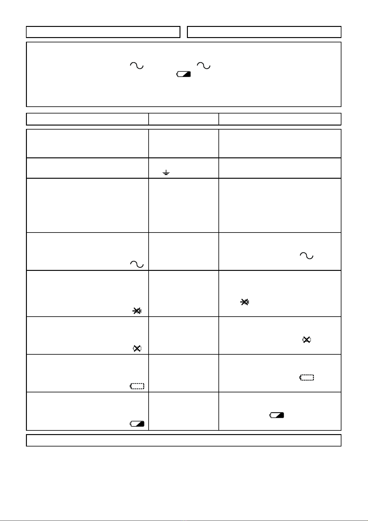
DESCRIZIONE DELLE SPIE LED DESCRIPTION
Se spente indicano rispettivamente la
mancanza del Modulo Alimentatore N. 1
oppure del Modulo Alimentatore N. 2.
OFF indicates failure on Power Supply
Module N. 1 or failure on Power Supply
Module N. 2 respectively.
Se spenta indica la mancanza della
tensione d’ingresso (230 V):
- controllare la presenza della tensione di rete;
- controllare che il fusibile 17 non sia bruciato:
- controllare che il Modulo Alimentatore sia
collegato all’Elettronica di Controllo.
OFF indicates input (230 V) voltage failure:
- check for main voltage presence;
- check that fuse 17 is not burnt;
- check that the Power Supply Module is
connected to the Electronics
Se spente indicano la mancanza della
tensione di uscita rIspettivamente sui
morsetti [O1], [O2] o [O3]:
- se manca la tensione di ingresso (spia
spenta), controllare che
l’accumulatore sia presente, connesso e
carico (spie , e spente);
- controllare che la corrente assorbita dal
morsetto non superi 1,8 A; in tal caso,
riportando l’assorbimento nel limite ammesso,
la tensione dovrebbe essere ripristinata.
OFF indicates output voltage failure on
terminals [O1], [O2] or [O3] respectively:
- if there is input voltage failure (LED
OFF), check that the battery is present,
connected and charged (LEDs ,
and OFF);
- check that the current absorbed by the
terminal does not exceed 1.8 A; if this is the
case, by bringing absorption within the
permitted limits, the power should be
restored.
Se accesa indica che il Modulo Alimentatore è
stato sconnesso perché la sua tensione di
uscita ha superato una soglia di sicurezza
(BXM12 = 15 V; BXM24 = 34 V) che potrebbe
danneggiare l’accumulatore e i dispositivi
collegati alla Stazione di Alimentazione: nel
frattempo l’alimentazione della Stazione e dei
dispositivi ad essa collegati è garantita
dall’accumulatore. Se la tensione di uscita del
Modulo Alimentatore torna sotto la soglia di
sicurazza, viene riconnesso automaticamente,
altrimenti esso deve essere sostituito.
ON indicates that the Power Supply
Module has been disconnected because
its output voltage exceeded the safety limit
(BXM12 = 15 V; BXM24 = 34 V), this may
damage the battery and the devices
connected to the Power Supply Station: in
the meantime the battery guarantees the
voltage to the Power Supply Station and
the connected devices. If the output
voltage of the Power Supply Module drops
below the safety limit, it is automatically
reconnected, otherwise, it must be
replaced.
Se accesa indica che che l’accumulatore è
stato sconnesso perché la sua tensione è
scesa sotto una soglia di sicurezza (BXM12
= 9,5 V; BXM24 = 19 V) che potrebbe
danneggiarlo in modo irreversibile. Esso
sarà riconnesso non appena il Modulo
Alimentatore sarà in grado di ricaricarlo.
ON indicates that the battery has been
disconnected because the voltage
dropped below the safety level (BXM12 =
9.5 V; BXM24 = 19 V), this may damage
the battery irreversibly. The battery will be
reconnected as soon as the Power Supply
Module is able to recharge it.
DESCRIZIONE MORSETTI v(V) i(A) TERMINAL DESCRIPTION
Uscite di alimetazione protette da
fusibile autoripristinante. 1[O1]
3[O2]
5[O3] (1) (2) Supply outputs protected by
automatic restoral fuse.
Morsetti di massa. 2-4-6-14
[ ] 0-- Terminals for negative.
Uscita antisabotaggio Normal-
mente Chiusa: si apre quando si
rimuove il pannello frontale della
Stazione di Alimentazione oppure
quando quest’ultima viene
strappata dal muro.
7-8[AS] -- --
Normally Closed tamper output:
opens when the front panel of the
Power Supply Station is removed
or when the Power Supply Station
is pulled off the wall.
Uscita di ripetizione Normalmente
Appesa di Avaria Rete: si collega
alla massa quando si accende la
spia .
9
[AV.RETE] 00,1
Normally Open repeat output for
Main Trouble: connects to
negative when the LED lights.
Uscita di ripetizione Normalmente
Appesa di Sconnessione Modulo
Alimentatore: si collega alla
massa quando si accende la spia
.
10
[SW. DIS] 00,1
Normally Open repeat output for
Power-Supply Cutout Module:
connects to negative when the
LED lights.
Uscita di ripetizione Normalmente
Appesa di Sconnessione Accu-
mulatore: si collega alla massa
quando si accende la spia .
11
[B DIS] 00,1
Normally Open repeat output for
Battery Cutout: connects to
negative when the LED . lights.
Uscita di ripetizione Normalmente
Appesa di Accumulatore
Assente: si collega alla massa
quando si accende la spia .
12
[B ASS] 00,1
Normally Open repeat output for
Battery Not Present: connects to
negative when the LED lights.
Uscita di ripetizione Normalmente
Appesa di Accumulatore Basso:
si collega alla massa quando si
accende la spia .
13
[B BAS] 00,1
Normally Open repeat output for
Low Battery: connects to negative
when the LED lights.
27,6V per la BXM24. 13,8V per la BXM12. (1) 27.6V for the BXM24. 13.8V for the BXM12.
DESCRIZIONE DELLE SPIE LED DESCRIPTION
Se accesa indica che l’accumulatore è
scarico: nel caso in cui venga a mancare
la tensione di ingresso (spia spenta)
l’alimentazione dei dispositivi collegati alla
Stazione non è garantita. Attendere alcune
ore per vedere se l’accumulatore si
ricarica, altrimenti sostituirlo.
ON indicates that the battery is
discharged: if the input voltage fails (LED
OFF) power to the devices
connected to the Power Supply Station is
not guaranteed. Wait for several hours to
check if the battery is recharged,
otherwise, the battery must be replaced.
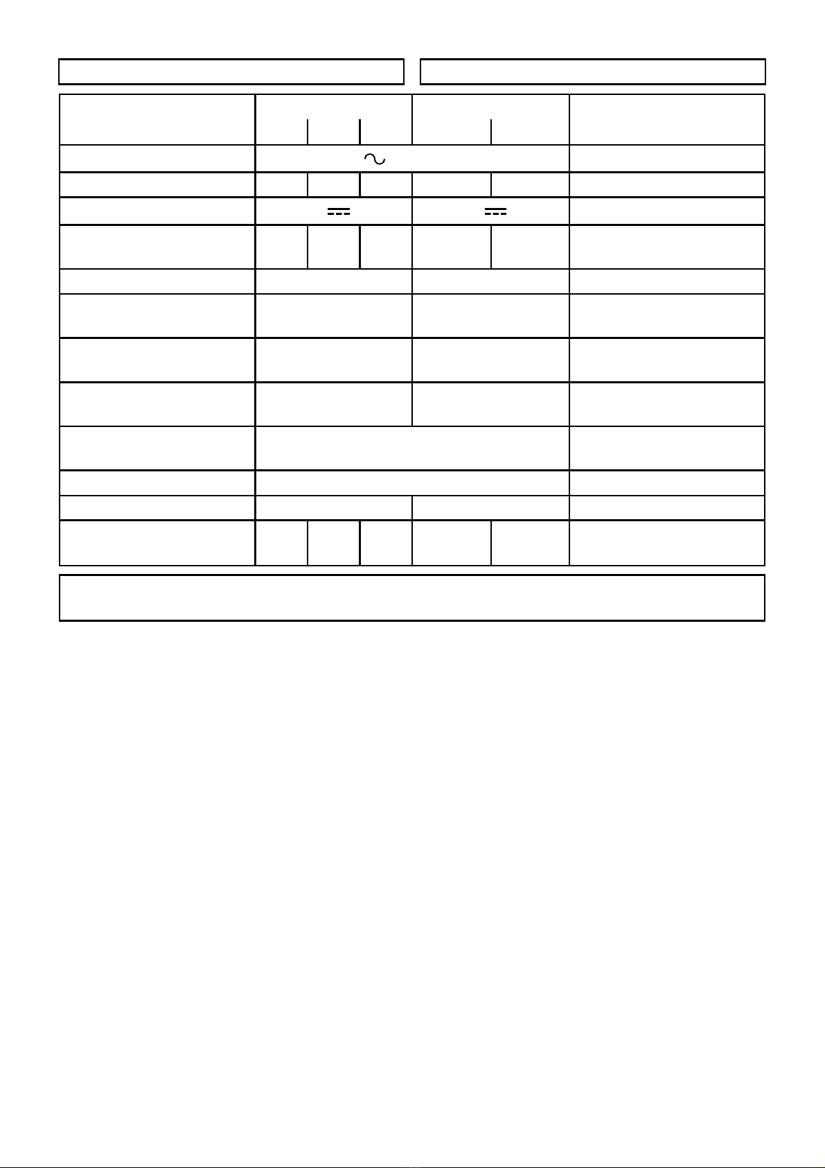
CARATTERISTICHE TECNICHE TECHNICAL CHARACTERISTICS
Modello BXM24 BXM12 Model
/14 /25 /50 /30 /50
Tensione di ingresso 230 V ±10% 50/60 Hz Input voltage
Corrente assorbita (max.) 0,5 A 0,9 A 1,8 A 0,5 A 0,9 A Absorption current (max.)
Tensione di uscita 27,6 V ±1% 13,8 V ±1% Output voltage
Corrente massima
erogabile 1,4 A 2,5 A 5,0 A 3.0 A 5.0 A Maximum current
supplied
Accumulatori allocabili 2 x [12 V 17 Ah] (3) [12 V 17 Ah max.] Battery housing
Soglia di Sconnesione
Modulo Alimentatore 34 V 15 V Power supply Module
Cutout Threshold
Soglia di segnalazione
Batteria Bassa 22 V 10,8 V Low Battery signalling
Threshold
Soglia di Sconnessione
Accumulatore 19 V 9,5 V Battery Cutout Threshold
Temperatura di
funzionamento 5 ÷40 °C Operating temperature
Classe di isolamento Classe IInsulation level
Dimensioni (L x H x P) 383 x 408 x 97 mm 240 x 348 x 97 mm Dimensions (W x H x D)
Peso (con accumulatori
da 17 Ah) 15,9
Kg 16,0
Kg 16,5
Kg 8,6 Kg 8,7 Kg Weight (with 17 Ah
battery)
I due accumulatori da 12 V vengono collegati
in serie per fornire una tensione di 24 V. (3) The two 12 V batteries should be
connected in series in order to supply 24 V.
This manual suits for next models
1
Table of contents
Other Bentel Security Power Supply manuals


Popular Power Supply manuals by other brands

TDK-Lambda
TDK-Lambda Genesys Series user manual

Moxa Technologies
Moxa Technologies V2416A Series Quick installation guide

Preen
Preen AFV-P Series user manual

alfatronix
alfatronix PV-USB1 Operating & assembly instructions

Lathem
Lathem PS8-2412 Specifications

National Instruments
National Instruments FD-11601 CALIBRATION PROCEDURE


