GENERAL INSTRUCTIONS
Adjustment of burner
The burner is from the factory pre-set
to an average value that must then be
adjusted to the boiler in question.
All burner adjustments must be made
inaccordancewithboilermanu-facturers
instructions. These must include the
checking of ue gas temperatures,
average water temperature and CO2
or O2concentration.
General instructions
The installation of the gas burner
must be carried out in accordance
with current regulations and standards.
The installers of gas burners should
therefore be acquainted with all regu-
lations and ensure that the installation
complies with the requirements. The
installation, mounting and adjustment
should be made with the greatest
care and only the correct gas should
be used.
Operating instructions
The operating instructions accom-
panying the burner should be left
in a prominent position in the boiler
room.
Instructions
The user should be thoroughly
instructed in the function of the gas
burner and the whole installation.
The supplier must instruct the user.
Inspection and maintenance
Daily inspection is advisable.
Start up
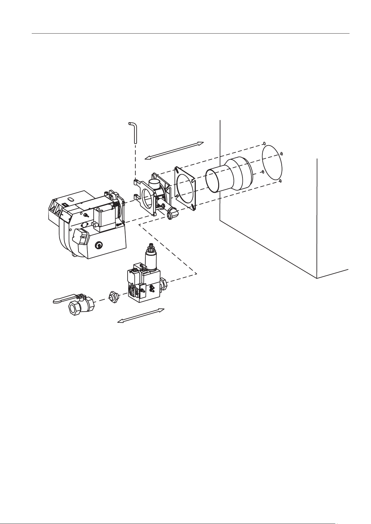
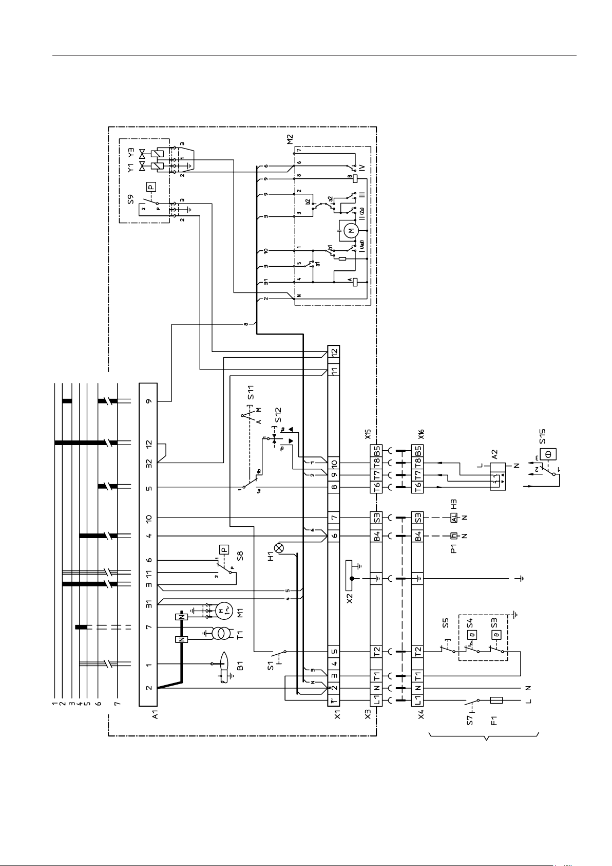
After the burner has been tted to
the boiler and the electric connection,
the leakage control, the venting and
the electric function test have been
carried out, the burner will be ready
for start-up.
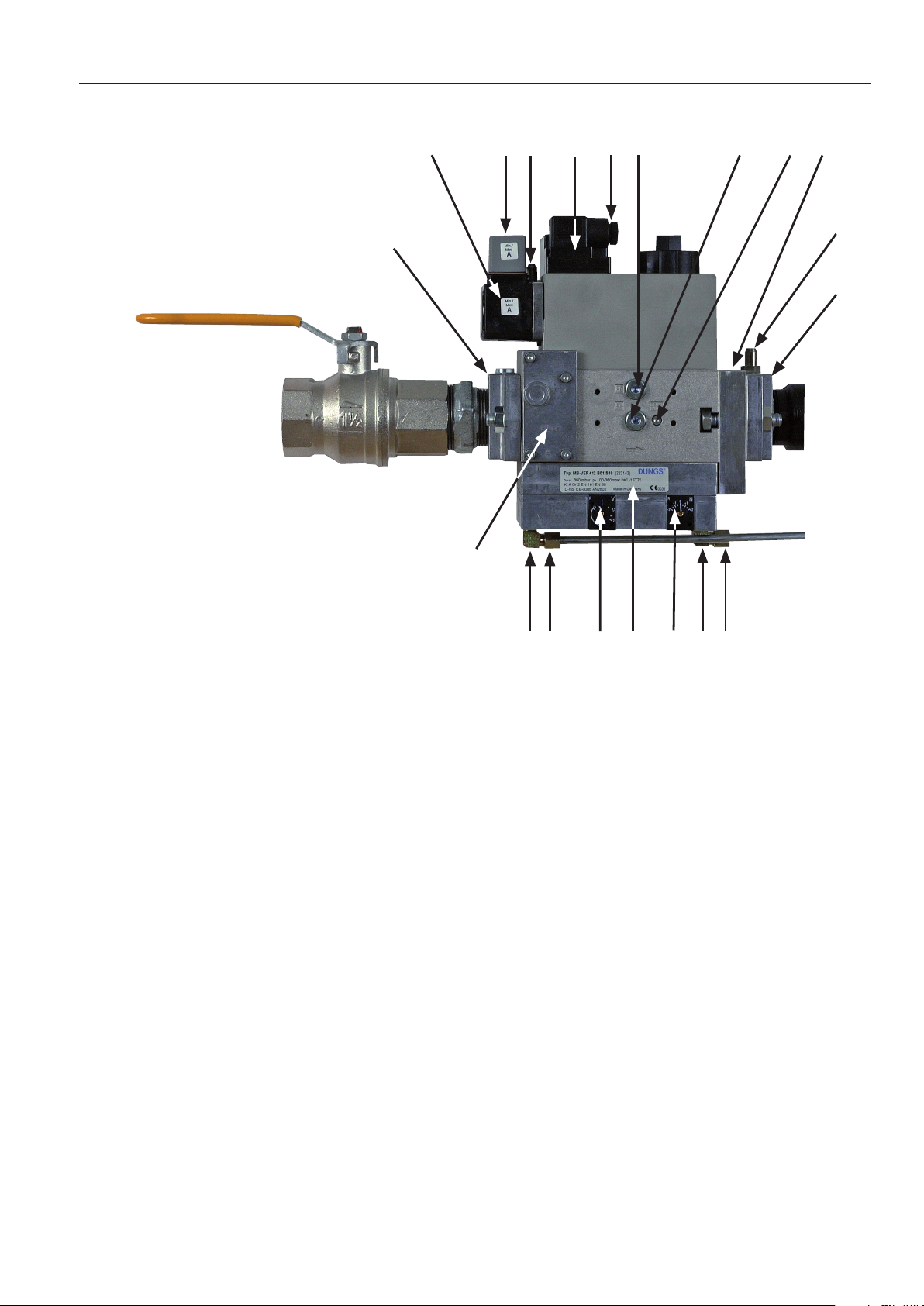
Howerer, study the sections dealing
with adjustments of multi-bloc, com-
bustion air and combustion head.
Open the ball valve and switch on the
main switch. If the burner starts the
actual adjustment can be made.
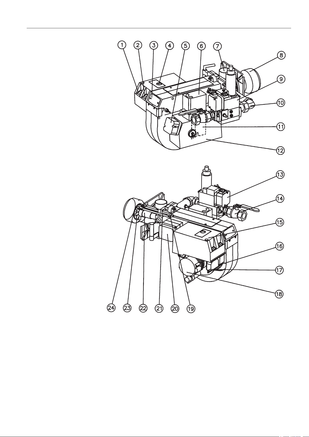
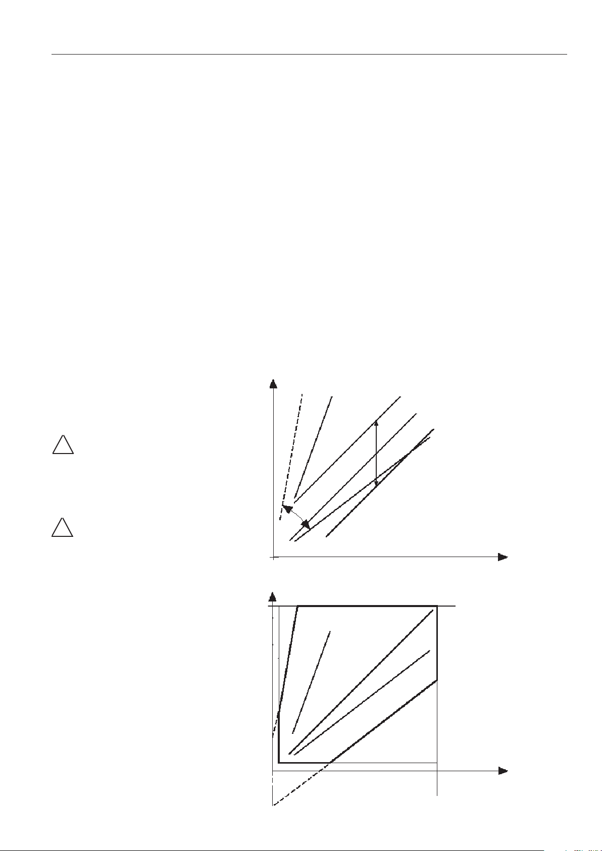
Adjustment of burner head
The burner is equipped with an adjust-
ment device changing the position of
thebrakeplateintheburnerhead.This
is used to adjust the correct pressure
drop over the combustion device in
order to obtain a good pulsation free
combustion.
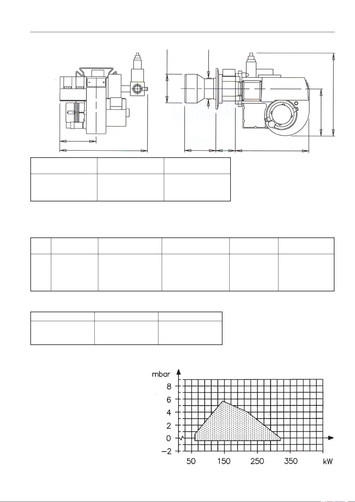
Which position to use depends on
input and overpressure in the boiler.
172 305 28 07-01
A general rule is that the lower capacity
the smaller the opening between
brake plate and combustion device.
Commissioning of installation
Control of the combustion. The com-
bustion quality is checked by means
ofauegasanalysisdevice.Adjust
theburnertoappr.20%excessair
in accordance with the table. Check
theuegastemperature.Calculate
theefciency.Checkalsotheactual
gas volume on the gas meter so that
the correct input is achieved.
Service
Service should only be carried out
byqualiedpersonnel.Replacement
parts should be of the same make and
approved by the same authorities as
the original. If the burner is converted
toreanothergasqualityitmustbe
re-commissioned. If town gas is to be
redthecombustion headmustbe
converted and the gas train adjusted
to suit (e.g.a larger gas armature or a
different spring in the governor may
be required).
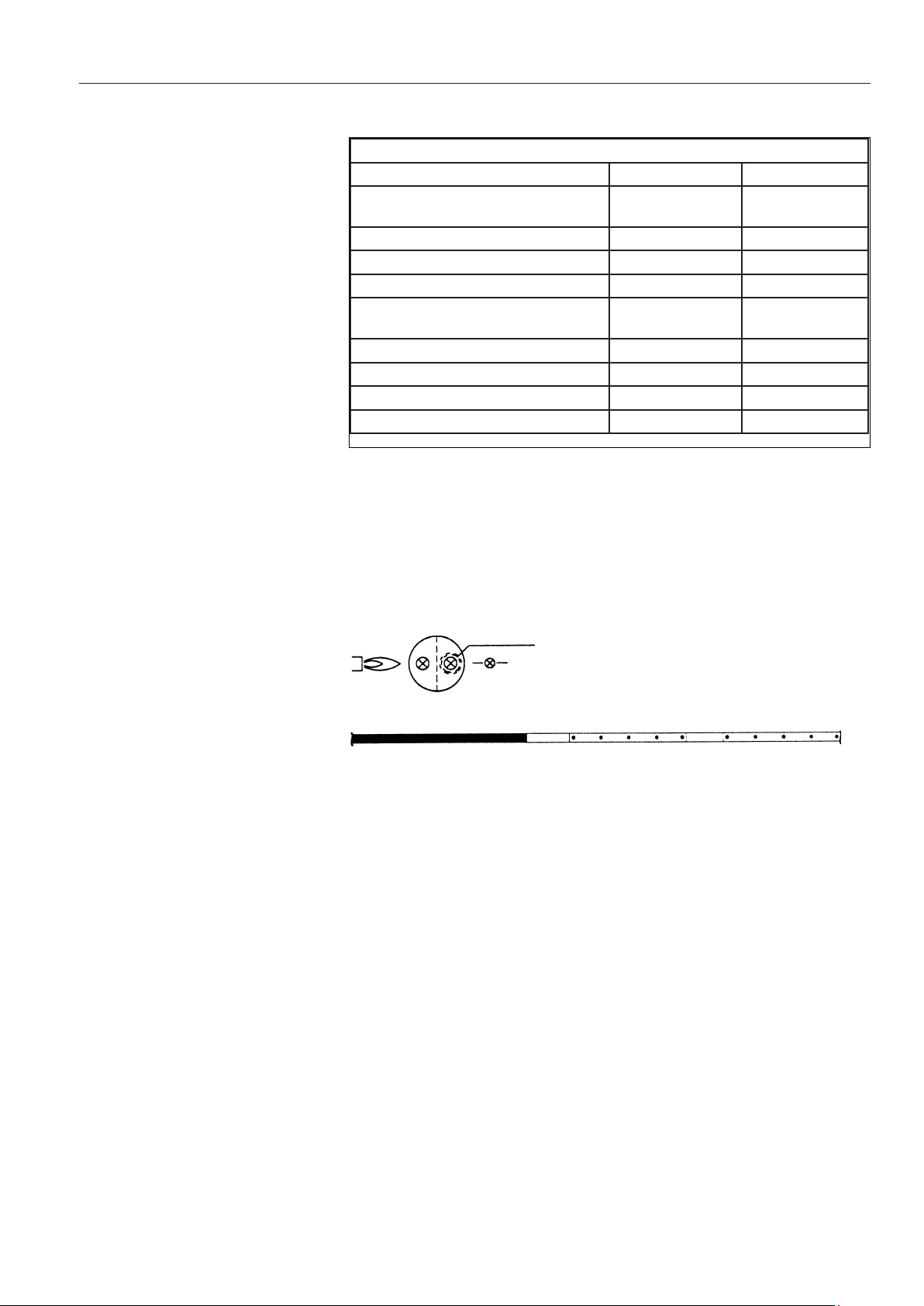
Gas quality CO2%
lambda 1,2
02%max. CO2%
Natural gas 10,0 3,5 11,9
LPG 11,5 3,5 13,9