8
quello generale dell'impianto su "spento"
· chiudere i rubinetti del combustibile e dell'acqua, sia
dell'impianto termico sia del sanitario
· svuotare l'impianto termico e sanitario se c'è rischio di
gelo
- la manutenzione dell’apparecchio deve essere eseguita
almeno una volta all'anno, programmandola per tempo
con il Servizio Tecnico di Assistenza.
Per la sicurezza è bene ricordare che:
è sconsigliato l'uso dell’apparecchio da parte di bambini o
di persone inabili non assistite
è pericoloso azionare dispositivi o apparecchi elettrici, quali
interruttori, elettrodomestici ecc., se si avverte odore di com-
bustibile o di combustione. In caso di perdite di gas, aerare
il locale, spalancando porte e finestre; chiudere il rubinetto
generale del gas; fare intervenire con sollecitudine il per-
sonale professionalmente qualificato del Servizio Tecnico
di Assistenza
non toccare l’apparecchio se si è a piedi nudi e con parti
del corpo bagnate o umide
prima di effettuare operazioni di pulizia, scollegare l’appa-
recchio dalla rete di alimentazione elettrica posizionando
l'interruttore bipolare dell'impianto e quello principale del
pannello di comando su "OFF"
è vietato modificare i dispositivi di sicurezza o di regolazione
senza l'autorizzazione o le indicazioni del costruttore
non tirare, staccare, torcere i cavi elettrici fuoriuscenti dal-
l’apparecchio anche se questo è scollegato dalla rete di
alimentazione elettrica
evitare di tappare o ridurre dimensionalmente le aperture
di aerazione del locale di installazione
non lasciare contenitori e sostanze infiammabili nel locale
dove è installato l'apparecchio
non lasciare gli elementi dell'imballo alla portata dei bam-
bini.
INSTALLAZIONE DELL’APPARECCHIO
FIG. 1 Connect AT/BT può essere installato “a parete” (pensile)
oppure “ad incasso” e può essere ubicato in prossimità della cal-
daia o in posizione remota purché la lunghezza dei collegamenti
idraulici ed elettrici, tra caldaia e Connect AT/BT, non superi 15
metri. Connect AT/BT può essere installato in luoghi esposti ad
agenti atmosferici (pioggia, sole, gelo, ecc) solo ed esclusiva-
mente “a incasso”.
Nota: i cablaggi in dotazione hanno una lunghezza di 2 metri.
In caso di installazione del Connect AT/BT con caldaie ad
incasso e collegamento elettrico effettuato sul lato inferiore
dell’unità da incasso, far sbordare di circa 10 cm (all’interno
di quest’ultima) il tubo corrugato.
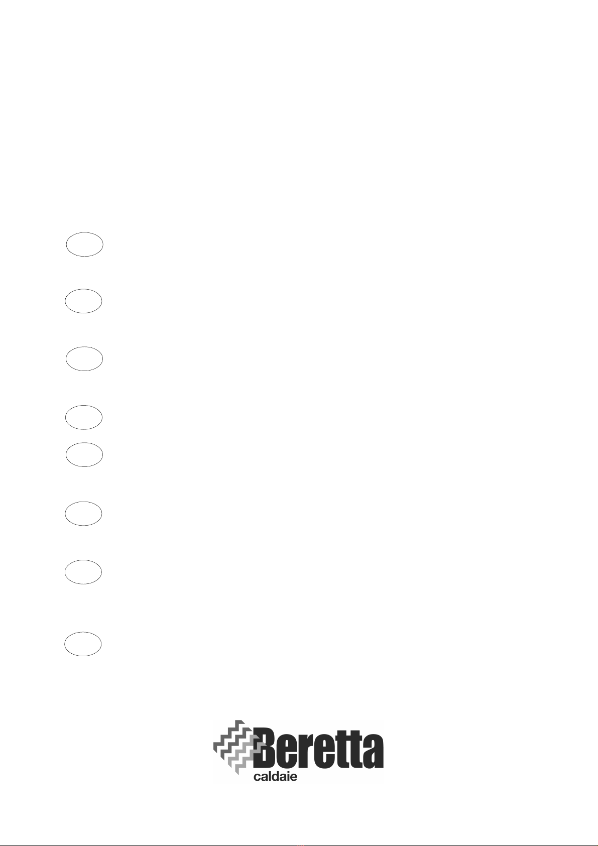
FIG. 2 Installazione “a parete” (pensile)
Quando Connect AT/BT viene installato “a parete” va supportato
con due tasselli ad espansione (forniti a corredo) adeguati al tipo
di parete ed al peso dell’apparecchio.
Si consiglia l’utilizzo di passatubi da posizionare sull’incasso per
limitare le infiltrazioni di acqua.
I passatubi non sono forniti con il dispositivo.
Grado di protezione IP10D.
FIG. 3 Installazione “a incasso “
Quando Connect AT/BT viene installato ad “incasso “ è necessario:
- predisporre le opere murarie realizzando una nicchia di
contenimento adatta alle dimensioni del Connect AT/BT ed allo
spessore della parete (valori indicativi minimi riportati in figura)
- posizionare Connect AT/BT nella propria sede ricordandosi di
aprire le due alette di sostegno per un migliore fissaggio
- proteggere i bordi laterali e il coperchio frontale durante i lavori
di incasso del dispositivo
Poiché gli allacciamenti idraulici ed elettrici tra impianto e Connect
AT/BT devono avvenire all’interno degli ingombri del dispositivo
stesso, occorre prima posizionare Connect AT/BT e poi i tubi di
ingresso ed uscita dell’impianto e la canalizzazione dei cavi elettrici.
Grado di protezione IPX4D.
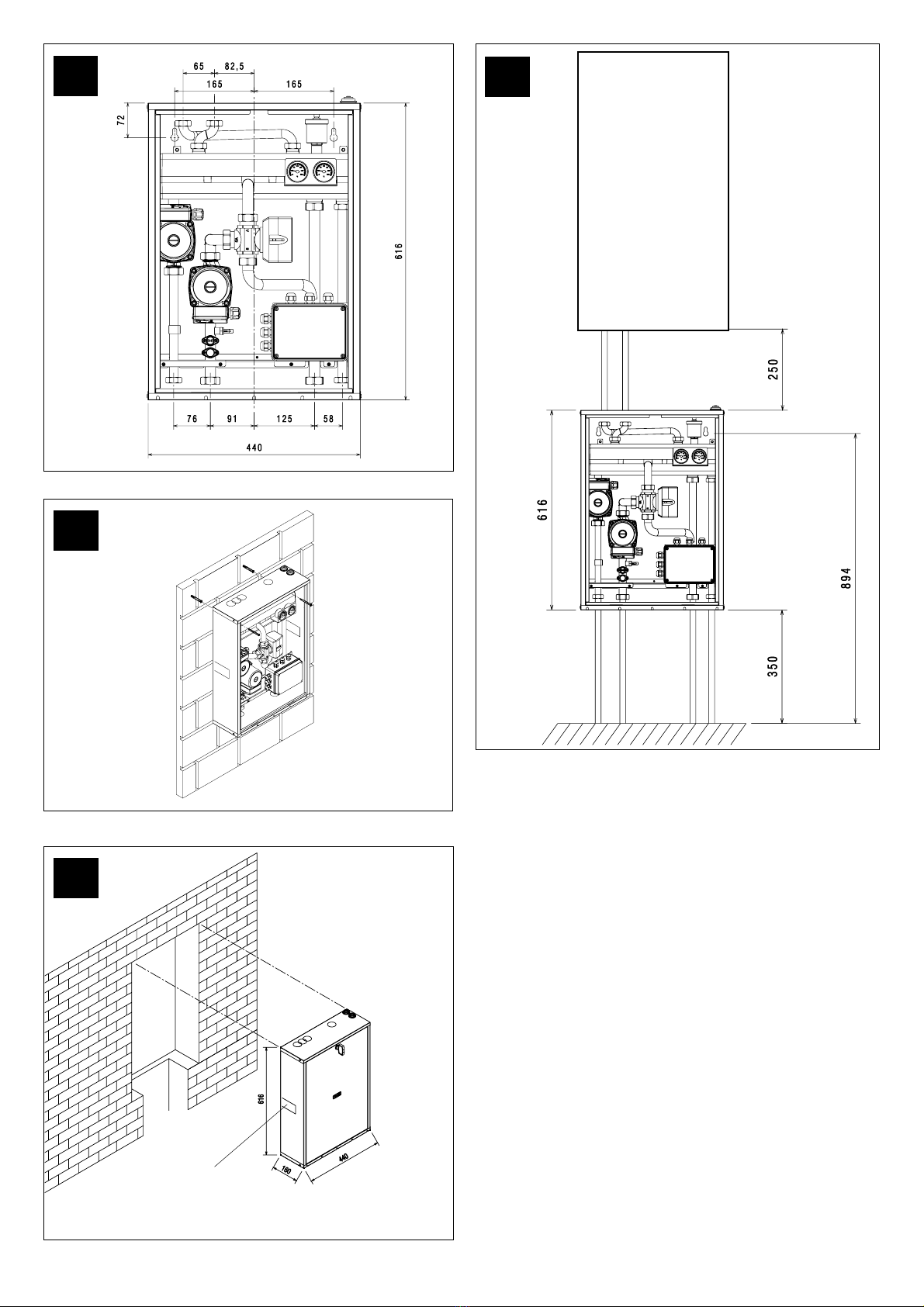
FIG. 4 Schema installazione tipica
La figura mostra un esempio di installazione del Connect AT/BT
NOTA: Per l’installazione di eventuali rubinetti (non forniti) occorre
predisporre la nicchia di dimensione tale da poterli installare sotto
Connect AT/BT stesso.
COLLEGAMENTI IDRAULICI
Prima di effettuare gli allacciamenti tutte le tubature devono esse-
re accuratamente lavate per rimuovere eventuali residui che po-
trebbero compromettere il buon funzionamento del Connect AT/BT.
FIG. 5
Gli allacciamenti idraulici verso caldaia e verso impianto devono
essere eseguiti in modo razionale riferendosi alla figura.
Gli allacciamenti possono avvenire direttamente utilizzando gli
attacchi femmina presenti sui tubi di mandata e ritorno del Connect
AT/BT o con l’interposizione su lato impianto di eventuali rubinetti
di intercettazione (non forniti).
Tali rubinetti risultano molto utili all’atto della manutenzione per-
ché permettono di svuotare solo il Connect AT/BT senza dover
svuotare anche l’intero impianto.
Verificare che il vaso d’espansione della caldaia sia di capa-
cità adeguata alle dimensioni dell’impianto.
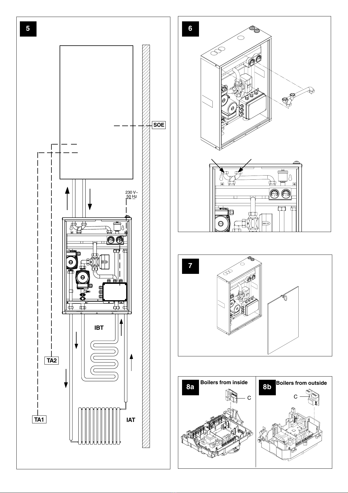
FIG. 6
Dopo aver installato Connect AT/BT è necessario procedere al
montaggio all’interno del Connect AT/BT stesso delle 2 rampe for-
nite a corredo (con relative guarnizioni) di interfaccia con gli interassi
caldaia (vedi disegno).
COLLEGAMENTI ELETTRICI
Per effettuare il collegamento elettrico del Connect AT/BT è ne-
cessario accedere al Connect AT/BT e alla scheda caldaia.
FIG. 7 Per accedere al Connect AT/BT :
- Togliere il pannello lamierato anteriore del Connect AT/BT
Qualora si volessero utilizzare cablaggi non in dotazione, è ne-
cessario utilizzare cavi con sezione di 0,50 mm2. Tali collegamenti
non devono avere una lunghezza superiore a 15 metri.
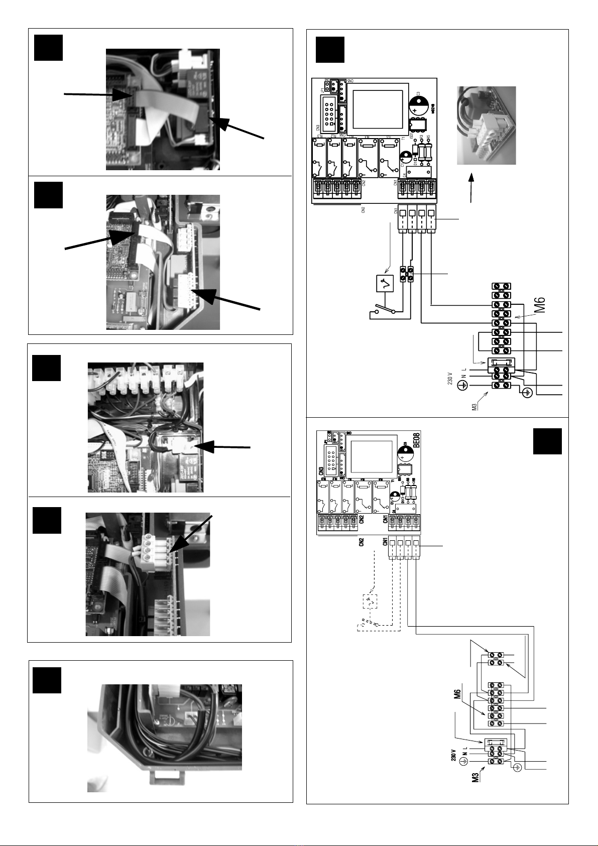
COLLEGAMENTO SCHEDA ELETTRONICA GESTIONE IMPIAN-
TI (a corredo) CON SCHEDA ELETTRONICA DELLA CALDAIA
Questa connessione viene realizzata con apposito cavo banda
piatta (a corredo).
La scheda elettronica gestione impianti deve essere inoltre ali-
mentata dalla tensione di rete.
Evitare che i cablaggi vengano a contatto con le resistenze
antigelo.
Per il collegamento procedere come segue:
1. Smontare il mantello di caldaia e aprire la copertura posteriore
cruscotto secondo quanto riportato nel libretto della caldaia
stessa.
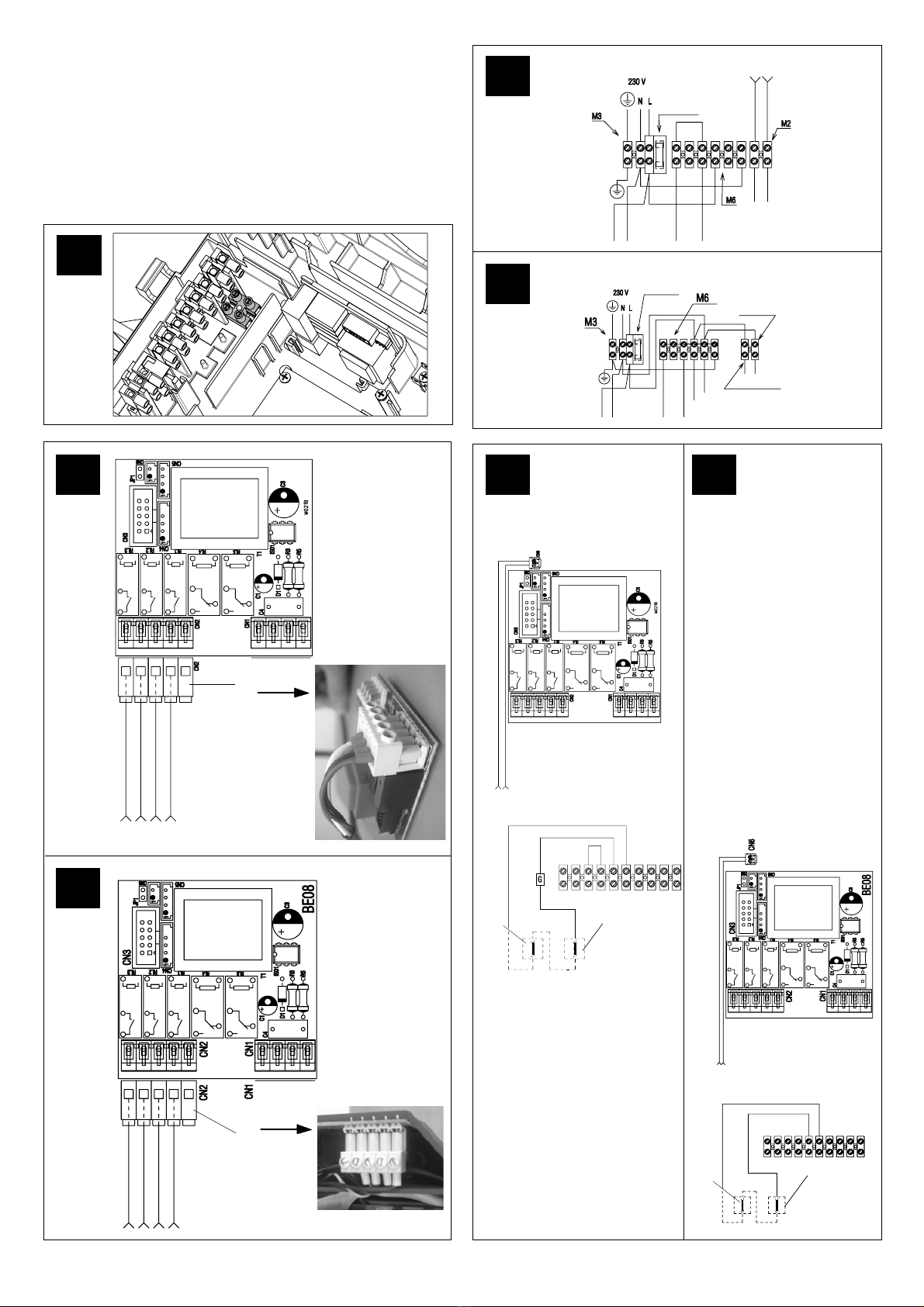
FIG. 8a-8b
2. Inserire la scheda elettronica gestione impianti a corredo (C)
nell’apposita sede all’interno del cruscotto