8COMMANDS
ENGLISH
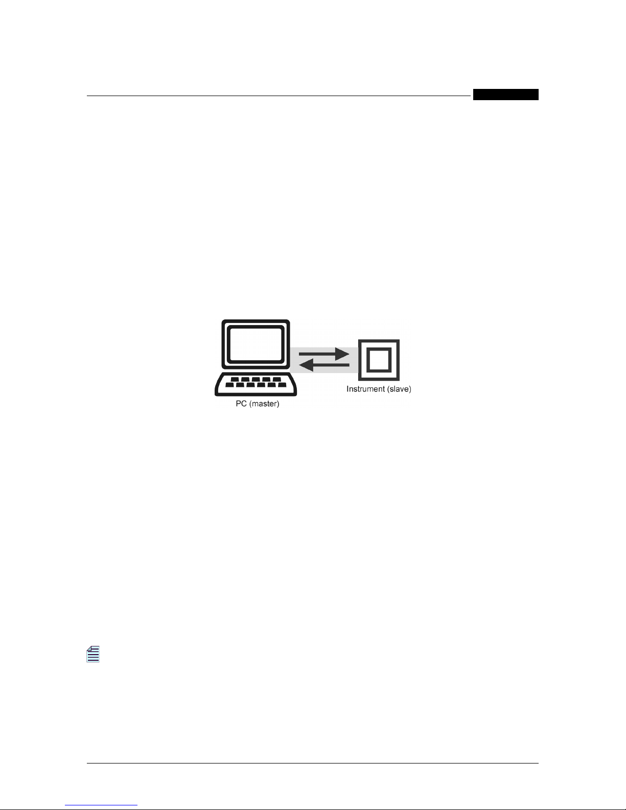
STANDARD Communication Protocol
4. COMMANDS
NOTE
The * symbol indicates a parameter available only when the instrument includes
the relevant option.
NOTE
“ENH” is the abbreviation for functions or parameters included only in the
Enhanced Package version of the instrument.
4.1 Measured Values (codes valid for read only)
R3D INSTRUMENT (Firmware Release 1.xx) COMPATIBLE ANSWER FORMAT
In case of wiring mode: 3Ph-4W/3CT
Answer format:
<STX> VΣV1 V2 V3 V12 V23 V31 AΣA1 A2 A3 THDA1 THDA2 THDA3 AN PFΣPF1
PF2 PF3 NUL COSØ1* COSØ2* COSØ3* VAΣVA1 VA2 VA3 WΣW1 W2 W3 varΣvar1
var2 var3 IN1 IN2 IN3 IN4 +Wh +varhI +varhC +VAh -Wh -varhI -varhC -VAh F THDV1
THDV2 THDV3 NUL RST <ETX><BCC>
Value format:
Instantaneous values•
sign (space, +, -) + value on 4 digits with decimal point (5 characters) + multiplier
(space, m, k, M, G, T, …)
Energy counters•
sign (space, +, -) + value on 6 digits with decimal point (7 characters) + multiplier
(space, m, k, M, G, T, …)
Digital inputs•
sign (space, +, -) + value on 8 digits with decimal point (9 characters) + multiplier
(space, m, k, M, G, T, …)
Phase reversal•
sign (space, +, -) + value on 3 digits with decimal point (4 characters) + multiplier
(space, m, k, M, G, T, …)
In case of wiring mode: 3Ph-3W/2CT
Answer format:
<STX> VΣNUL NUL NUL V12 V23 V31 AΣA1 A2 A3 THDA1 NUL THDA3 NUL PFΣ
NUL NUL NUL NUL NUL NUL NUL VAΣNUL NUL NUL WΣNUL NUL NUL varΣNUL
NUL NUL IN1 IN2 IN3 IN4 +Wh +varhI +varhC +VAh -Wh -varhI -varhC -VAh F NUL
NUL NUL NUL RST <ETX><BCC>
In case of wiring mode: 1Phase
Answer format:
<STX> NUL V1 NUL NUL NUL NUL NUL NUL A1 NUL NUL THDA1 NUL NUL NUL
NUL PF1 NUL NUL NUL COSØ1* NUL NUL NUL VA1 NUL NUL NUL W1 NUL NUL
NUL var1 NUL NUL IN1 IN2 IN3 IN4 +Wh +varhI +varhC +VAh -Wh -varhI -varhC
-VAh F THDV1 NUL NUL NUL RST <ETX><BCC>
R3D.01 MEASURED INSTANTANEOUS VARIABLES
In case of wiring mode: 3Ph-4W/3CT
Answer format:
<STX> VΣV1 V2 V3 V12 V23 V31 AΣA1 A2 A3 THDA1 THDA2 THDA3 AN PFΣPF1
PF2 PF3 NUL COSØ1* COSØ2* COSØ3* VAΣVA1 VA2 VA3 WΣW1 W2 W3 varΣvar1
var2 var3 IN1 IN2 IN3 IN4 +Wh +varhI +varhC +VAh -Wh -varhI -varhC -VAh F THDV1
THDV2 THDV3 NUL RST <ETX><BCC>
Command Description
UBN310 UBN315
UBN3080