BERG BRW 185 User manual

Berg Hortimotive 2-2016
Translated user manual BRW170+BRW185 V3_2016
1/27
MANUAL
This manual applies to the following types of pipe rail trolleys
BRW 185
Type: 22400 single scissors, hydraulic lift wheels, double operation
Type: 22405 double scissors, hydraulic lift wheels, double operation
Type: 22406 double scissors, hydraulic lift wheels, operation pole
Type: 22407 single scissors, hydraulic lift wheels, operation pole
BRW 170
Type: 22410 double scissors, hydraulic lift wheels and operation pole
Type: 22420 double scissors, manual lift wheels and operation pole
Type: 22421 single scissors, manual lift wheels and operation pole
Type: 22422 single scissors, hydraulic lift wheels and operation pole
Manufacturer : Berg Hortimotive
Address : Burg Crezeelaan 42a 2678 KZ DE LIER, THE NETHERLANDS
Type : 224……..
Serial number : ………….
Year of construction : ………….
Own weight : 270-304kg
Max. load : 250kg
Motor : 24V=, 0.18/0.37kW
Hydraulics : 24V=/0.5kW 200 Bar

Berg Hortimotive 2-2016
Translated user manual BRW170+BRW185 V3_2016
2/27
CONTENTS
1. INTRODUCTION 3
1.1 General 3
1.2 Supplier information 3
1.3 Warranty 3
2. SAFETY 3
2.1 Explanation of safety terms used 3
2.2 Safety regulations 4
2.3 Safety Symbols 6
3. INTENDED USE 7
3.1 Area of application 7
3.2 Location and nomenclature of parts and control functions 7
4. TRANSPORT 8
4.1 Forklift transportation 8
5. PUTTING INTO OPERATION 9
5.1 Inspection before use 9
5.2 Minimum requirements for pipe rail system
(horticulture industry directives) 9
5.3 Skewness indicator 10
6. APPLICATION 11
6.1 Operation 12
6.2 Not in use 14
6.3 Cleaning 14
6.4 Harvest container 15
6.5 Problems/causes/solutions 15
7. MAINTENANCE AND REPAIR 17
7.1 Pipe rail system maintenance 18
7.2 Technical maintenance 18
7.3 Battery maintenance 18
8. TECHNICAL SPECIFICATIONS 20
APPENDIX I MAINTENANCE LOGBOOK 21
APPENDIX II BATTERY SAFETY SHEET 22
APPENDIX III CLEANING THE POWDER COATING 26
APPENDIX IV DECLARATION OF CONFORMITY 27

Berg Hortimotive 2-2016
Translated user manual BRW170+BRW185 V3_2016
3/27
1. INTRODUCTION
1.1 GENERAL
Congratulations on making the right decision to purchase your pipe rail trolley from
Berg Hortimotive. You can now benefit from an excellent machine designed and
manufactured with the utmost care. You will gain most from your investment by strictly
observing the instructions for safety, use and maintenance outlined in this manual.
Read this manual carefully before putting the pipe rail trolley into operation. The
safety regulations, instructions and directions should be observed at all times.
Berg Hortimotive cannot be held responsible for direct or indirect damage should the
user fail to observe the instructions and safety directions outlined in this manual.
Berg Hortimotive liability is also nullified should you or a third party make any
modifications to this machine or accessories without our written consent.
The conditions in relation to the supply of the pipe rail trolley are in accordance with
the trade conditions filed at the Office of the District Court in The Hague on 15 August
1983, no. 83/106. A complimentary copy outlining these conditions will be sent to you
upon request.
1.2 SUPPLIER INFORMATION
Please contact your Berg Hortimotive dealer should your pipe rail trolley appear to
malfunction or have defects.
1.3 WARRANTY
For a period of 6 months after delivery, Berg Hortimotive gives the client a warranty
on material and manufacturing defects that occur during normal use. This warranty
does not apply if the defects are caused by improper use or causes other than by
material and manufacture, if Berg Hortimotive - following consultation with the client -
delivers used material or used goods or if the cause of the defects cannot be
demonstrated clearly.
The warranty provisions are set out in the METAALUNIE CONDITIONS as they read
according to the most recent relevant text. The terms and conditions of delivery are
available on request.
The warranty given by Berg Hortimotive for all goods and materials not manufactured
by Berg Hortimotive will never be more than that given by its supplier. The warranty is
ex works. Faulty machines and/or parts must be sent postage paid.
When it is not possible to send out machines or systems, any travel and subsistence
expenses will be payable by the client.
Sold and delivered goods with manufacturer's, importer's or wholesaler's warranties
are subject only to the warranty provisions set by the suppliers.
Hydraulic pumps are subject only to the manufacturer's warranty, provided the pump
comes with an undamaged safety seal from the supplier.
Berg Hortimotive accepts responsibility for the availability of replacement parts,
provided they are available from its suppliers at reasonable conditions.

Berg Hortimotive 2-2016
Translated user manual BRW170+BRW185 V3_2016
4/27
2. SAFETY
2.1 EXPLANATION OF SAFETY TERMS USED
Safety terminology
Danger: Indicates the possibility of severe injury that may lead to
death should the instructions in the manual be ignored.
Warning: Indicates the possibility of injury should the instructions
in the manual be ignored.
Be careful: Indicates possible damage to the machine should the
instructions in the manual be ignored.
Caution: Indicates possible problems that may occur should the
instructions in the manual be ignored.
2.2 SAFETY REGULATIONS
Please pay careful attention to the following safety regulations and observe them
closely at all times. Non-observance may endanger users working with the pipe rail
trolley.
DANGER
-Read the manual carefully. Observe instructions, safety regulations, etc., at all times.
-The pipe rail trolley is suitable for driving over a pipe rail system that complies with the
pipe rail system directives for the horticulture industry, outlined in paragraph 5.2
-Only use the Pipe Rail Trolley on a suitable pipe rail system. Check if the centre to
centre dimension (ctc) of the trolley matches the ctc of the pipe rail system.
-Never exceed the maximum loading capacity of 250kg.
- 1 person incl. load (+ harvest container only type 22400/22405)
-Never exceed the manual sideways effort of 8kg (force of 80N).
-Only use the pipe rail trolley for harvesting and crop maintenance.
-The pipe rail trolley should not be used if the skewness is greater than 2
.
- Skewness indicator on the trolley (acoustic signal).
-All loads should be placed in the centre of the operating platform as low as possible.
-Do not allow more than 1 person on the platform at a time.
-Do not use the undercarriage to ride on/along.
-Do not remove the safety rail.
-Do not increase the lift height by any means.
-Stay on the operating platform at all times.
-Keep at a safe distance from power cables and parts of the greenhouse construction.
-The pipe rail trolley should not be used, for the drawing of steel cables and screens.
- Use the pipe rail trolley only for the purpose for which it has been
designed.

Berg Hortimotive 2-2016
Translated user manual BRW170+BRW185 V3_2016
5/27
-Never use the pipe rail trolley as a crane.
-Do not allow people and/or pets to walk on the path if a pipe rail trolley is present.
-Do not use multiple pipe rail trolleys/machines in the same path.
-All protective screens and coverings should be in place and closed during use of the
pipe rail trolley.
-Only use harvest containers (types 22400/22405) manufactured by Berg Hortimotive.
-The harvest container with push-rack should be mounted on the designated place on
the operating platform (BRW185). The container and push-rack should overhang the
front or back of the pipe rail trolley by a maximum of 500mm.
-Harvest containers should only be filled with lightweight harvest products such as
peppers/capsicums. A maximum total weight of 100kg applies.
WARNING
-The pipe rail trolley should only be operated if no other people are in the vicinity of the
trolley.
-The pipe rail trolley should only be operated by persons aged 16 or over who have
received adequate training with regard to the trolley and who have studied the contents
of this manual.
-The pipe rail trolley should only be operated if positioned correctly on the pipe rail
system.
-All personnel working in the vicinity of the pipe rail trolley should be fully familiarised
with the safety provisions and regulations
- Employer’s instruction.
-The batteries should be charged at least twice a week!
-The pipe rail trolley should only be repaired by specially trained personnel by Berg
Hortimotive.
-During scissor maintenance, the scissors should be supported by the scissor-wedge at
all times.
-Never carry out maintenance activities to the pipe rail trolley when it is being operated.
-Check the pipe rail trolley for faults on a daily basis.
-Keep operating equipment and safety pictographs clean.
- Operating functions and safety pictographs need to be clearly visible
at all times.
-The key should be removed from the contact when leaving the Trolley unattended.
-Never leave the pipe rail trolley unattended.
- Unless the key has been removed from the socket.
-Always turn the pipe rail trolley off during maintenance.
- Take the key out off the main switch and disconnect the charger.

Berg Hortimotive 2-2016
Translated user manual BRW170+BRW185 V3_2016
6/27
-Do not carry out any modifications to the pipe rail trolley without written consent from
Berg Hortimotive.
-Only use accessories and parts supplied by Berg Hortimotive.
-Stop at the end of the path to check that no other people are in the vicinity.
-On the operating platform the load’s total height may not exceed 40 cm.
-Remove obstacles, such as plant refuse, from the track before entering a path.
-Never clean the pipe rail trolley with water and/or a steam cleaner.
-Fully retract the scissors when moving the trolley sideways.
-Never use the pipe rail trolley on a public road or outside.
-The trolley should be in the lowest position if someone wants to leave the platform.
-Observe the safety regulations for the batteries (see maintenance).
-Always stand beside the lift bar if the trolley is raised by using the manual lift system
for sideways movements. Hold the bar with one hand while moving the trolley.
-Disconnect the charger before using the pipe rail trolley.
CAUTION!
-Keep your work place tidy.
- A cluttered work area can lead to dangerous situations.
-Concentrate. -Ensure full concentration at all times when using the pipe rail trolley.
Do not use the pipe rail trolley if not fully concentrating.
2.3 Safety Symbols
Read manual
before use!
Before
maintenance,
disconnect and
read instruction
manual!
Be careful! Stay away with
hands, possible cutting
hazard!
Be careful, descending
platform! Use safety bar!
Electricity!
Figure 2.1;Safety pictograms on scissors and trolley
Safety lowering valve, push
to descend!
Max 250kg
1. Maximum sideways force 200N
2. Maximum load 250kg
3. Maximal 1 person
4. Maximum skewness 2º
5. Only use indoors!
6. Pipe diameter and thickness in mm
7. Maximal suppot distance 1250mm

Berg Hortimotive 2-2016
Translated user manual BRW170+BRW185 V3_2016
7/27
3. INTENDED USE
3.1 AREA OF APPLICATION
The pipe rail trolley is intended for professional use within the horticultural sector. The
trolley should be operated by one person only, aged 16 or over, who has received
adequate training with regard to the pipe rail trolley and who has studied the contents
of this manual. The pipe rail trolley is intended to drive over a pre-installed pipe rail
system in accordance with industry directives and its sole purpose is to aid the
nurture, maintenance or harvest of crops/plants. Do not use the pipe rail trolley for
applications other than those described. The trolley is designed to carry one person
and loose goods with a maximum total weight of 250kg. The pipe rail trolley should
only be manned if positioned correctly on the pipe rail system.
3.2 LOCATION AND NOMENCLATURE OF PARTS AND CONTROL FUNCTIONS
Fig. 3.1
Fig. 3.2
Lower operating platform
Emergency stop
Speed regulator
Raise operating platform
Drive-direction indicator
Drive direction
Pause
Control panel
Safety bar
Foot switch
Lift system
Scissor Safety bar (wedge)
Drive roll
Emergency descent and stop key
switch. Selector switch auto/manual
drive
Emergency lowering valve
Nylon flange roll

Berg Hortimotive 2-2016
Translated user manual BRW170+BRW185 V3_2016
8/27
4. TRANSPORT
-Secure the pipe rail trolley during transport at all times.
- Ensure the pipe rail trolley is kept dry during transport.
- Cover the pipe rail trolley with waterproof material during transportation in an open
platform truck.
-Turn off the trolley before transport with the main switch and press the emergency
button.
4.1 FORKLIFT TRANSPORTATION
- Place the fork of the forklift in the middle under the chassis of the pipe rail trolley.
- Before lifting with the forklift, verify that the fork is correctly positioned under the pipe
rail trolley in order to prevent unnecessary damage to the trolley.
- Never lift higher than necessary and make sure the forklift can lift the total weight of
the trolley.
Fig. 3.4
End switch lift retracted
Motor
Batteries
Drive (speed) control
Automatic fuses
Main fuse 5A
Hydraulic pump
Charge socket
Fig. 3.3
Operation Drive control Motor Skewness Indicator Cylinder lift system
Switch lift retracted Fuses Batteries Hydraulic pump Oil Reservoir

Berg Hortimotive 2-2016
Translated user manual BRW170+BRW185 V3_2016
9/27
5. PUTTING INTO OPERATION
The pipe rail trolley is specifically designed for driving over a pipe rail system. The
trolley should be inspected on all points outlined in section 5.1 before being put into
operation.
The pipe rail system must meet the pipe rail system directives for the horticulture
industry. Section 5.2 outlines the minimum pipe rail specifications with regard to track
width, pipe diameter and support distance. These specifications are taken from the
pipe rail system directives for the horticulture industry.
5.1 INSPECTION BEFORE USE
The following points should be checked before using the Trolley for the first time.
-Cables, hoses and general mechanical parts for damage.
-Damage to the operating components including buttons and switches.
-Drive pulleys, flanged pulleys and swiveling wheels.
-Batteries fully charged.
-Safety pictograms are visible.
-Protective covers and caps are in place.
-Proper connection/ fastening additional parts such as double scissors or
safety bar.
-All buttons are functioning correctly.
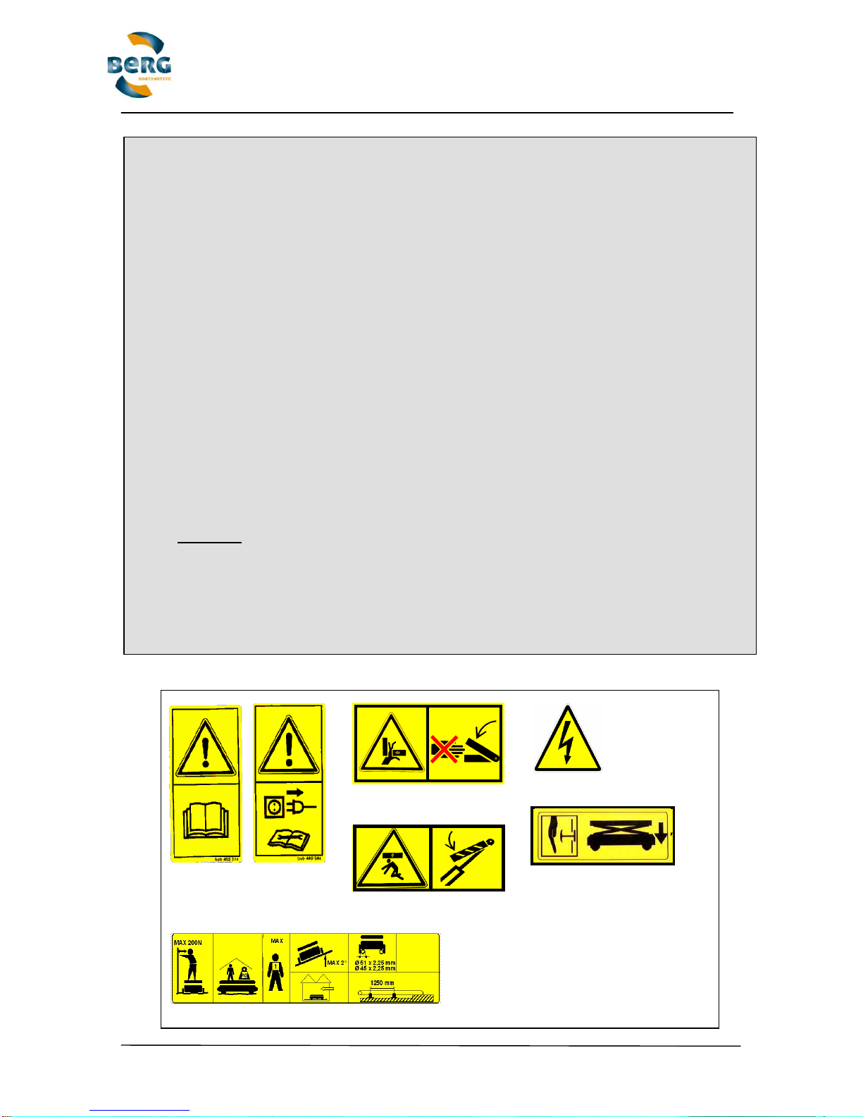
5.2 MINIMUM REQUIREMENTS FOR PIPE RAIL SYSTEM (horticultural industry
directives)
The Pipe Rail Trolley has been specially designed to drive on a pipe rail system. The
pipe rail system must satisfy the most recent requirements of the horticultural sector
guidelines for pipe rail systems. Figure 5.1 provides the minimum requirements for the
pipe rail system which have been taken from the horticultural sector guidelines for
pipe rail systems. The pipe rail system on which the Trolley is intended to be used,
must also comply with these requirements. All mentioned items should also be
checked periodically. It is absolutely prohibited to use the Trolley on a pipe rail system
that does not comply with the following requirements. Furthermore a couple of tests
has to be carried out, to test the combination of pipe rail trolley and pipe rail system,
according to the directives.
The pipes must be stable, accurately installed and level and with a slope of no more
than 2either in length or in width. The pipes must also be properly attached to the
supports and the concrete track. Loose fitting pipes may not be used! A soil test bore
should be carried out using probing equipment (see policy regulation). It should have
a so-called cone value on the top layer of more than 0.4 Mpa (62 psa).
An incompatible pipe rail system may be used provided that a stability test has been
carried out according to the policy regulation for pipe rail systems, and it appears that
the combination of the pipe rail wagon and system are stable. Furthermore, the
supports on a non-standard pipe rail system must be maximum 1.25 m apart.
(See article 1.1 for the (Dutch) policy regulation regarding pipe rail systems)

Berg Hortimotive 2-2016
Translated user manual BRW170+BRW185 V3_2016
10/27
5.3 SKEWNESS INDICATOR
The pipe rail trolley is equipped with a skewness indicator. The indicator transmits an
acoustic signal if the trolley exceeds a obliquity of 2°. In the latter event, all activities
should be ceased immediately and the pipe rail system readjusted/levelled.
1.1 The pipe rail system should be erected in such a way that the stability of the pipe rail wagons, which are designed to run on the
rails, should never present a dangerous situation. To that end the following should be taken into account:
a) pipe rail supports should all correspond, or at least be of the same specifications: steel base plates 1.5 mm thick with reinforcing
sections; base plate width at least 115 mm; and long enough so that the base plates stick out a minimum of 70 mm from the two
upright supports which carry the pipes.
b) pipes should correspond, or at least be of the same specifications given in the table below:
TABLE: Pipes
Category
Track width
in mm 6
Pipe diameter / wall
thickness in mm
Support distance
in mm
Permissible axle weigh
in kg with St 33 1, 2, 3, 7, 8
1
420 to 600
Ø 51 / 2.25
max 1250
260 4
2
550 to 600
Ø 51 / 2.25
max 1670
220 5
3
420 to 600
Ø 45 / 2
max 1000
221 4
4
420 to 600
Ø 45 / 2
max 1250
177 4
5
420 to 600
Ø 38 / 2
max 1000
157 4
6
420 to 600
Ø 38 / 2
max 1250
126 4
1Using Steel 37 (St 37) the permissible axle weight can be raised by a factor of 1.2.
2The permissible axle weight depends on the length of the wheelbase of the wagon with regard to the support distances: the axle
weight given in the table applies to pipe rail wagons with a wheelbase less than 62.5% or those greater than 125% of support
distance.
3Using wagons with a wheelbase greater than 62.5% but less than 125%of the support distance, the permissible axle weigh may
raised by a factor of 1.3.
4The permissible axle weight is given for a track width of 420. With wider track widths the permissible axle weight is raised by the
following correction factors: 1.08 with track width 500 mm; 1.13 with track width 550 mm; and 1.17 with track width 600 mm.
5The permissible axle weight is given for a track width of 550 mm. The permissible axle weight for a track width of 600 mm may be
raised by a 1.04 correction factor.
6The track width is the centre to centre distance between the pipes. For a track width greater than 600 mm, the same permissible
axle weight can used as for 600 mm.
7If a smaller support distance is used than shown in the table above, then the permissible axle weight may be higher than given:
the correction factor is changed in proportion to the reduction in the support distance.
8Using pipe rail wagons with an axle weight greater than shown in the table is only permitted if it is clear that the wheel pressure in
unfavourable load conditions is no greater than 75% of the loading level where the rails begin to buckle, and for no more than 5
mm from the original; and the carrying capacity of the pipe rail support is not exceeded (according to item 1.1, a) with respect to the
foundation; that being a load of 300 kg.
Fig. 5.1; Chapter 1.1 of Article 1 of Policy Regulation 3.2; Pipe Rail Systems in
Greenhouses Working Conditions Act (10-02-2004).

Berg Hortimotive 2-2016
Translated user manual BRW170+BRW185 V3_2016
11/27
6 APPLICATION
Make sure you are familiar with your pipe rail trolley and control functions. Ensure
that operators have received instructions regarding the pipe rail trolley and the
safety regulations and have studied this manual.
The pipe rail trolley should only be operated if it has been verified that no other
people are present in the near vicinity of the trolley.
Supplementary equipment is available to facilitate access onto the pipe rail trolley.
Only use equipment manufactured by Berg Hortimotive. Do not use equipment from
other manufacturers.
Remove crop refuse and other obstacles from the pipe rail system before use.
Keep the trolley clean by regularly removing dirt build-up. Prior to cleaning, switch
the trolley off by removing the key (main switch) from its socket.
Only operate the pipe rail trolley after you have studied the previous pages and all
your questions have been answered.
Remove the red key from the socket after use.
Maintain the pipe rail trolley on a regular basis and keep it in a dry storage area (not
the greenhouse) if it is expected to be idle for an extended period of time.
Charge the batteries at least twice a week! Less frequent charging will reduce
the capacity of the batteries and the lifetime of the batteries, the motor and the
drive control!
CAUTION! DANGER! HANDLING BATTERIES CAN CAUSE INJURY!
Avoid skin contact with battery fluid. Wear safety glasses and gloves. Battery fluid is
a strong corrosive acid. Upon contact, immediately wash skin with water and soap.
In the event of eye contact rinse with running water for at least 10 minutes and seek
medical assistance. When working with or near batteries, ensure that adequate
supplies of water and soap are nearby and that assistance is available within
earshot. Avoid short-circuiting (spark formation) and ensure that no (electric)
connection is made between the battery poles.
Extremely explosive gas is released during battery recharge. Ensure that no fire or
sparks are near the batteries during the recharge. NO SMOKING!
Make certain the area is well ventilated during battery recharge or battery storage
(more about charging; see chapter maintenance).
Make sure that no metal objects can fall on the battery as this can cause short-
circuiting or sparks and, consequently, an explosion. Remove personal items such
as bracelets, rings, necklaces and watches when working near the battery. A short-
circuit current is capable of melting a ring and causing severe burns.

Berg Hortimotive 2-2016
Translated user manual BRW170+BRW185 V3_2016
12/27
6.1 OPERATION
OPERATING PANELS
Depending on the type of trolley, the trolley is equipped with two operating panels
enabling the user to operate the trolley from both sides, or with one operating pole.
PAUSE BUTTON (1)
From models supplied in 2016 this button has no function.
BUTTON TO RAISE THE OPERATING PLATFORM (2)
Use this pressure switch to raise the operating platform. On attaining the maximum
height, release the push button to prevent unnecessary excess pressure in the lift
cylinders. The platform raises as long as the button is pushed.
EMERGENCY STOP SWITCH (3)
- Push in to stop
- Turn right/pull to release
The emergency stop switch is used to turn the pipe rail trolley off in an emergency.
In the event of the emergency stop switch being released, the key switch needs to
1 2 3 4 5 6 7
8 9
3 5
2
7
1 6 4
8 9
3
5
6
2
7
10
Figure 6.1b; operation console
(only brw185. Buttons 1-7 equal on both sides )
Figure 6.1a
above; operation pole standard
underneath; lifting buttons in platform
(both 170 and 185)
Figure 6.1c; operation pole with big buttons
(only brw185)

Berg Hortimotive 2-2016
Translated user manual BRW170+BRW185 V3_2016
13/27
be reset by switching off and then on again. This reinstates the standard setting. In
other words: the green arrow is continuously on (forward); the foot switch in means
drive; and the foot switch is released to stand still. When turning off the Trolley, use
the main switch (11).
DRIVE DIRECTION SELECTION BUTTON (4)
The drive direction changes when the button is pressed. The drive direction is
shown by the drive direction indicator (6).
SPEED REGULATOR (5)
The speed function in linear between zero and ten.
0 = standstill 10 = maximum speed
DRIVE DIRECTION INDICATOR, “FORWARD” / “BACKWARD” (6)
The drive direction indicator flashes and transmits a pulsing sound signal, indicating
that the batteries need to be recharged soon. When flashing one arrow, the Trolley
is paused. When one arrow aluminates, the indicated direction is preset.
BUTTON TO LOWER THE OPERATING PLATFORM (7)
Use this pressure switch to lower the operating platform. The platform will lower as
long as the button is pushed. Beware of any persons or obstacles near the
scissors!
RETRACT LIFTING WHEELS (8) only when equipped with hydraulic lifting wheels
Pressing this button will result in retracting the lifting wheels for sideways
transportation. Push the button until the wheels are fully retracted.
LIFT THE TROLLEY WITH THE LIFTING WHEELS (9) only when equipped with hydraulic
lifting wheels
Press the button to lift the Trolley for sideways transportation (between paths).
DO NOT use the lifting wheels when driving on pipe rail, only standing on a flat and
hard surface. In addition, the scissors should be fully retracted.
MAIN SWITCH / EMERGENCY STOP (11)
The pipe rail trolley can be turned on (vertical) and off (horizontal) using the main
switch. When the emergency stop has been used, the main switch should be turned
off and on again to reset the trolley. The red key should be removed from its socket
Figure 6.2; Operation on the trolley. Left: BRW185, Right: BRW170
12 11
11 12

Berg Hortimotive 2-2016
Translated user manual BRW170+BRW185 V3_2016
14/27
when the trolley is left unattended. The Switch also functions as emergency stop;
turn to stop all movement of the trolley and scissors.
CHARGER PLUG POWER POINT (12)
The Trolley is fitted with two batteries that should be recharged using only a
specially suitable charger supplied by Berg Hortimotive. The batteries should be
charged at least once every two weeks. Never deplete the batteries completely.
Remove plug from socket before using the trolley!
EMERGENCY DESCENT VALVE
The emergency descent valve is positioned underneath the scissors at the end
opposite of the main switch end. The emergency descent valve can be used in an
emergency to lower the operating platform so the operator can step off safely. The
platform descends as long as the button is pushed. CAUTION: Beware not to get
stuck underneath the platform or between the scissors! Only use this valve in
case of an emergency!
FOOT SWITCH
There are one or two foot switches on the operating platform which, when pressed,
allows the pipe rail trolley to drive.
MOVING PIPE RAIL TROLLEY SIDEWAYS WITH LEVER (types 22420/22421)
By pulling the lever situated before the operating pole down, the wheel-set extends
underneath the pipe rail wheels enabling the pipe rail trolley to be moved sideways.
(When equipped with hydraulic lifting wheels, see explanation above nr.2 and 7)
Always hold the lever with one hand during sideways transportation. Push the
Trolley with the other hand. Beware that the lever does not flicks backward!
The scissors should be retracted completely when transporting the trolley sideways!
6.2 NOT IN USE
The pipe rail trolley should be stored in a dry frost-proof room when not in use for an
extended period. Charge the batteries at least once a week! The trolley should be
placed on a level surface. If the pipe rail trolley is likely to be out of use for a long
time, it should be covered with a protective sheet, the ignition key removed and the
fuse box switched to the “0” position. When next required (after being out of use for
a long time period), the trolley should be inspected again as outlined in section 5.1
(inspection before use).
6.3 CLEANING
Remove plant refuse and sharp materials such as sand and dust. Clean the pipe rail
trolley with a dry/moist cloth. Never pour water over the pipe rail trolley or clean with
a steam or high-pressure cleaner as this may cause severe damage to the electrical
circuit.
6.4 HARVEST CONTAINER (type: 22400 / 22405)
The pipe rail trolley can be supplemented with a harvest container (see photograph).
Only use harvest containers manufactured by Berg Hortimotive The harvest
container is mounted on a push-rack and should overhang the front or back of the
pipe rail trolley by a maximum of 500mm. Harvest containers should only be filled

Berg Hortimotive 2-2016
Translated user manual BRW170+BRW185 V3_2016
15/27
with lightweight harvest products such as peppers. The maximum total weight of the
container is 100kg. Never exceed the maximum loading capacity of the pipe rail
trolley (250kg).
6.5 PROBLEMS / CAUSES / SOLUTIONS
Problem A : The pipe rail trolley fails to drive
Cause : Empty batteries (drive direction indicator 4a/4b flashes).
Solution : Recharge batteries.
Main switch OFF
Put key in and turn vertical
Battery clips make poor contact.
Clean battery poles and re-affix clips
Emergency stop is pushed in.
Release emergency stop and turnkey switch on.
Foot switch is defect
Replace foot switch.
The foot switch’s cable is broken.
Replace cable.
Reversing switch is faulty.
Consult your dealer.
The carbon brushes are worn.
Consult your dealer.
Dirty sliding contacts.
Consult your dealer.
Other causes.
Consult your dealer.
>>>More problems and solutions on next page!
Problem B : The operating platform cannot be raised or lowered
Cause : Empty batteries (drive direction indicator 4a/4b flashes).
Solution : Recharge batteries.
Battery clips make poor contact.
Clean battery poles and re-affix clips.
Emergency stop is pushed in.
Release emergency stop and reset key switch.
Overloaded.
Reduce the load.
Too little hydraulic oil.
Add hydraulic oil.
Pipe rail Trolley
type: 22400 with
harvest container

Berg Hortimotive 2-2016
Translated user manual BRW170+BRW185 V3_2016
16/27
Problem C : Difficulties regulating speed.
Cause : Speed regulator is not properly secured.
Solution : Secure button.
Operation printed circuit board is faulty.
Consult your dealer.

Berg Hortimotive 2-2016
Translated user manual BRW170+BRW185 V3_2016
17/27
Smeernippel 6x1 H2-M 45gr.
7 MAINTENANCE AND REPAIR
The pipe rail trolley is a product of extremely high quality. In order to safeguard this
quality, the maintenance guidelines below should be strictly observed. Repairs and
maintenance activities should be recorded in the maintenance logbook (see page
19). In addition, employers are obliged, at all times, that their means of labour
should be in strict conformity with means of labour regulations. To ensure this,
means of labour should be inspected periodically.
DAILY MAINTENANCE ACTIVITIES AND INSPECTIONS:
-Check batteries charge
-Check operating components & safety pictographs for visibility and damage
WEEKLY MAINTENANCE ACTIVITIES:
-Clean and grease foot switch(es).
-Clean operating panel.
-Check for oil leakages. Inspect cables and hydraulic pipes for damage.
-Check for loose electrical connections.
-Inspect drive roll, wheels and other components for mechanical damage
-Charge batteries and check level of distilled water in batteries.
-Clean wheels and chain. Remove wind up rope and leaves.
-Check whether lifting/lowering movements runs smoothly (low hydraulic oil).
MONTHLY MAINTENANCE ACTIVITIES:
-Clean and grease battery poles.
-Grease pivot points (scissors). Clean and oil drive
chain.
-Oil lifting wheels and ball bearings.
ANNUALLY MAINTENANCE ACTIVITIES:
-Replace any carbon brushes shorter than 1cm.
-Check welds of the scissors construction for cracks, hairline cracks and rust.
Contact your pipe rail trolley dealer immediately should a fault become apparent
during one of the inspections mentioned above. Do not use the trolley under these
circumstances.
During maintenance on, below, or in between the scissors construction, place the
scissors-wedge supplied at the bottom side of the scissors between the scissors
connecting link and the scissors. Raise scissors, place wedge on frame. Lower
scissors and make sure the wedge is placed in the cutout. Lower the scissors as far
as possible, turn OFF and disconnect charger.
The scissors-wedge
supplied should be
placed at this point
during maintenance
on the scissors
construction.

Berg Hortimotive 2-2016
Translated user manual BRW170+BRW185 V3_2016
18/27
Battery empty
Battery charged
Floater must float
to read valid
value
Scale
Floater
Battery acid
Read
Read
7.1 PIPE RAIL SYSTEM MAINTENANCE
The pipe rail system used for the Berg Hortimotive’s pipe rail trolley should be
inspected periodically. The system must conform to the directives for pipe rail
systems in the horticulture industry. Do not use a pipe rail system that fails to meet
the specified directives. Employers are also obliged to periodically check their
means of labour and ensure these conform to the means of labour regulations.
7.2 TECHNICAL MAINTENANCE
Repairs and maintenance on the parts mentioned below must be carried out by a
qualified professional recognised by the manufacturer:
All work relating to electrical components and wiring.
All work relating to the hydraulic system.
All work relating to the motor drive and reduction gear unit except for cleaning,
readjustment or replacement of the chain and chain wheels.
All maintenance should be noted in the maintenance logbook (appendix).
7.3 BATTERY MAINTENANCE
Charge the batteries at least twice a week with a suitable charger!! Prevent the
batteries from becoming depleted completely!
Please contact your dealer for a comprehensive product information pack on
batteries. Please find below directions for use and maintenance.
CAUTION!
-Explosive gas is released during battery recharge. Avoid smoking, fire and
naked flames.
-Only recharge the batteries in well-ventilated areas.
-Check fluid levels on a weekly basis. The battery fluid must be at least 1cm
above the plates.
-Only fill up with distilled water.
The battery’s lifespan is reduced considerably if
recharged unnecessarily. Immediate recharge of
empty batteries substantially increases the
lifespan. The lifespan of the batteries and charger
are adversely affected if the batteries are
discharged to under the 20% level Consequently,
the specific gravity of the acid should preferably be
checked on a weekly basis using an acidimeter.
The density of fully charged batteries is 1.28kg/l.
Percentage Density (in kg/l) = Voltage (Volts)
100% 1.28 12.7
80% 1.24 12.5
60% 1.21 12.3
40% 1.17 12.1
20% 1.14 11.9

Berg Hortimotive 2-2016
Translated user manual BRW170+BRW185 V3_2016
19/27
Before charging turn off the Trolley with the main switch, second connect the
charger to the batteries before turning the charger on. When recharged, turn the
charger off before disconnecting. Recharging “too far” can damage the batteries as
the battery fluid boils for longer than necessary. It is advisable to use a modern
battery charger with automatic cut-out.
Only use a charger suitable for a 24V-110Ah Wet battery (see instructions on
charger).
- Never interrupt the recharging process until fully finished
- During battery recharge do not repair, clean or carry out any other activities to the
pipe rail trolley
- When dismantling the batteries, disconnect all power consumers in order to avoid
spark formation.
- At dismantling, the negative cable (-) needs to be disconnected first. Conversely,
when installing, connect the negative cable last.
CAUTION!
Always connect the positive (+ = red) to the positive pole and negative (- =
blue) to the negative pole.
Battery fluid is a corrosive acid –prevent contact with clothes, skin and eyes. In the
case of splashes on skin or clothes, immediately wash with water and soap. Then
rinse with plenty of water. Acid splashes in the eyes should be rinsed with clean
water for at least 5 minutes. Medical advice should then be sought immediately.
Note
Check the permitted number of battery chargers on one group. You can check this by
multiplying amps of the fuse with the voltage. For example: 16A*230V = 3620W
Check the power consumption of the battery charger. Share the this capacity by the power
consumption of the battery charger. For example: 3620/700=5,17. 5 battery chargers can be
connected.
Check also if the tension on the charge location corresponds to the required tension which on
the battery charger indicate is. It can
Occur that tension loss appears in long cables.
When replacing batteries, hand your old ones in to your supplier or local authority.

Berg Hortimotive 2-2016
Translated user manual BRW170+BRW185 V3_2016
20/27
8 TECHNICAL SPECIFICATIONS
BRW 185
Type: 22400 single scissors, hydraulic lift wheels, double operation
Type: 22405 double scissors, hydraulic lift wheels, double operation
Type: 22406 double scissors, hydraulic lift wheels, operation pole
Type: 22407 single scissors, hydraulic lift wheels, operation pole
BRW 170
Type: 22410 double scissors, hydraulic lift wheels and operation pole
Type: 22420 double scissors, manual lift wheels and operation pole
Type: 22421 single scissors, manual lift wheels and operation pole
Type: 22422 single scissors, hydraulic lift wheels and operation pole
Type:
Dimensions [mm]:
22400
22405
22406
22407
22410
22420
22421
22422
Length
1850
1850
1850
1850
1700
1700
1700
1700
Wide =
ctc distance*1+ … [mm]
115
115
115
115
115
115
115
115
Step height
400
530
530
400
700
700
590
590
Height operation pole
-
-
1250
1250
1250
1250
1250
1250
Platform length
1800
1800
1800
1800
1500
1500
1500
1500
Platform wide
400
400
400
400
400
400
400
400
Platform max. height
1700
2950
2950
1700
2700
2700
1600
1600
Max. lifting weight [kg]
250
250
250
250
150
150
150
150
Own weight [kg]
275
304
304
275
290
290
270
270
Drive power [kW]
Optional:
0.18
0.37
0.18
0.37
0.18
0.37
0.18
0.37
0.18
0.37
0.18
0.37
0.18
0.37
0.18
0.37
Drive power hydr. [kW]
0.5
0.5
0.5
0.5
0.5
0.5
0.5
0.5
Hydr.oil Q8 Handle [L]
1.35
1.4
1.4
1.35
1.35
1.35
1.3
1.3
Max. drive speed [m/min]
with 0.37kW:
40
70
40
70
40
70
40
70
40
70
40
70
40
70
40
70
Raise/lifting speed [mm/s]
110
110
110
110
110
110
110
110
Voltage [Volt DC]
24
24
24
24
24
24
24
24
Battery capacity [Ah]
2x110
2x110
2x110
2x110
2x110
2x110
2x110
2x110
Wheelbase
1362
1362
1362
1362
1208
1208
1208
1208
*1;ctc distance = distance from pipe center to pipe center
This manual suits for next models
1
Table of contents
Other BERG Scissor Lift manuals
Popular Scissor Lift manuals by other brands

DINGLI
DINGLI JCPT0607DCS Operator's manual

Oshkosh Corporation
Oshkosh Corporation JLG 530LRT Operation and safety manual

Draper
Draper SLX14 Installation & operating instructions

Loxam
Loxam Nationwide Platforms GS2668 RT Emergency Lowering Instructions

Challenger Lifts
Challenger Lifts DX77R-LF Installation, operation & maintenance manual

Terex
Terex Genie GS-3384 Operator's manual