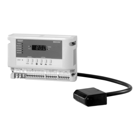
Berger Lahr WDP3-01X User manual

Positioning Controller for
3-phase Stepping Motors
WDP3-01X
Edition:g156 08.03
Ident. no.: 00441109760
Software version: 02.0XX

Safety requirements
Please read the following safety requirements prior to installation, operation, maintenance and repair
of the device.
•The intended use of the device is described under “Purpose” and must be observed.
•Installation, maintenance and repair of the device shall be performed by a qualified electrician.
National regulations concerning
– accident prevention
– installation of electrical and mechanical systems
– radio interference suppression
shall be observed.
•The technical data of the device, particularly the ambient conditions, shall be observed.
•The device shall only be operated by trained personnel.
•The warranty is invalidated in case of unauthorized modification or opening of the device.
•Please ask your technical consultant prior to installing accessories not listed in the chapter
“Description of accessories”.
•The safety symbols and notes on the device and in the manual shall be observed.
Explanation of symbols
ATTENTION
Reference to a danger for the device or components, possibly resulting
in the endangering of human life.
DANGER
Reference to a direct endangering of human life.
DANGER
High voltage at component, do not touch.
DANGER
High temperature at component, do not touch.
ATTENTION
Warning against electrostatic discharge (ESD).
Only touch the PC board or component in an electrostatically protected
environment.
NOTE
Important or additional information concerning the device or the manual.

Proposals
Improvements
Berger Lahr GmbH &Co. KGWDP3-01X
Breslauer Str. 7
Postfach 1180
D-77901 Lahr Edition: g156 08.03
Ident. no.: 00441109760
Sender: Please inform us, using this form, if
you have discovered any errors
when reading this document.
We should also appreciate any new
ideas and proposals.
Name:
Company/department:
Address:
Telephone no.:
Proposal and/or improvements:


Table of contents
Page
1 General description 1-1
1.1 Structure and characteristics 1-1
1.2 Function 1-2
1.2.1 Hardware components 1-2
1.2.2 Operating modes and system environment 1-6
1.2.3 Principle of a reference movement 1-11
1.3 Technical data 1-12
1.3.1 Electrical data 1-12
1.3.2 Mechanical data 1-16
1.3.3 Ambient conditions 1-16
2 Installation 2-1
2.1 Scope of supply 2-1
2.2 Accessories 2-2
2.3 Mounting 2-3
2.4 Wiring 2-5
2.4.1 Mains connection 2-7
2.4.2 Motor connection 2-8
2.4.3 Signal interface 2-9
2.4.4 Analog interface (OPT.1) 2-14
2.4.5 RS 232 serial interface (OPT.1) 2-16
2.4.6 RS 485 serial interface (OPT.1) 2-18
2.4.7 Field bus interface (OPT.1) 2-20
2.4.8 Encoder interface (OPT.2) 2-21
2.5 First start-up 2-24
Table of contents
WDP3-01X Ident. no.: 00441109760

Page
3 Operation 3-1
3.1 Functions 3-1
3.2 Switching ON/OFF 3-2
3.2.1 Switching on 3-2
3.2.2 Operation with brake 3-3
3.2.3 Switching off 3-3
3.3 Front panel operation 3-4
3.3.1 Parameter setting 3-7
3.3.2 Position set input via front panel 3-10
3.3.3 Teach-in via front panel 3-11
3.3.4 Value display on front panel 3-12
3.3.5 Starting positioning and other operations 3-13
3.3.6 Manual movement via front panel 3-14
3.4 Manual mode via inputs/outputs 3-15
3.5 Teach-in mode via inputs/outputs 3-17
3.6 Position processing via inputs/outputs 3-19
3.7 Upload/download via serial interface 3-22
3.8 On-line command processing via serial or field bus interface 3-23
3.9 Electronic gear 3-26
3.10 Oscillator mode via inputs/outputs 3-28
3.11 Oscillator mode via analog interface 3-30
3.12 Rotation monitoring 3-32
Table of contents
WDP3-01X Ident. no.: 00441109760

Page
4 Malfunctions 4-1
4.1 Status indicators 4-1
4.2 Troubleshooting tables 4-3
4.3 Repair work 4-6
4.4 Storage, shipment 4-6
5 Customer service 5-1
6 Appendix 6-1
6.1 Device variants 6-1
6.2 Description of accessories 6-2
6.2.1 Fan 6-4
6.2.2 Mains filter 6-5
6.2.3 MP 923 interface converter 6-6
6.2.3.1 General description 6-6
6.2.3.2 Technical data 6-6
6.2.3.3 Setup 6-7
6.2.3.4 Status indicators 6-7
6.2.4 MP 924 interface distributor 6-9
6.2.4.1 General description 6-9
6.2.4.2 Technical data 6-9
6.2.4.3 Setup 6-10
6.2.5 Additional bleed resistor 6-11
6.3 Glossary 6-12
6.4 Abbreviations 6-15
Table of contents
WDP3-01X Ident. no.: 00441109760

Page
7 Index 7-1
8 Corrections and additions 8-1
Table of contents
WDP3-01X Ident. no.: 00441109760

1 General description
1.1 Structure and characteristics
The WDP3-01X positioning controller (fig. 1-1) can be used for controlling
the following BERGER LAHR3-phase stepping motors witha rated
motor voltage of 325 V:
Purpose
– WDP3-014 motors of type size 90, (VRDM 39xx/50 LWB)
– WDP3-018 motors of type size 110, (VRDM 311xx/50 LWB)
One unit is used for controlling one axis. The difference between the
positioning controllers WDP3-014 and WDP3-018 consists in their power
ratings.
Additional interface options allow you to implement various device func-
tions. The controller detects the interfaces installed and configures itself
automatically for the appropriate device functions.
Interface options and
device functions
This documentation describes installation and operation via the front
panel keys and the inputs/outputs of the signal interface as well as via the
analog and encoder interfaces. Setup and operation of the unit via the
serial interface or the field bus interface (e.g. Interbus-S or Profibus-DP)
are described in separate documentations on the appropriate interface.
Documentation
L
N
PE
Serial interface
or
Analog interface
or
Field bus interface
(option)
Motor connector
Mains
connector
Selector switch
for mains voltage
115 VAC or 230 VAC
Status display
Front panel keys
Bleed resistor connection
(only at units < RS40)
Signal interface
Encoder interface
for electronic gear
or rotation monitoring
(option)
230V
Fig. 1-1 WDP3-01X
positioning controller
General description
WDP3-01X Ident. no.: 00441109760 1-1

1.2 Function
1.2.1 Hardware components The actual function of the controller depends on the configuration of the
interface adapter slots OPT.1 and OPT.2.
The following configuration options are available:
Interface configuration
for OPT.1 and OPT.2
Interface
adapter slot Device functions
OPT.1 OPT.2
Not
installed Not
installed Oscillator mode or position processing
via inputs/outputs
– Position processing via inputs/outputs
or front panel, or oscillator mode via
inputs/outputs (can be set with front
panel parameter P00)
– Manual mode via inputs/outputs or front
panel
– Teach-in mode via inputs/outputs or
front panel
– Position and parameter input via front
panel
RS 422 – Rotation monitoring, if parameter
P20 = 2 and P00 ≠3
RS 232
or
RS 485
Not
installed Position processing via inputs/outputs or
on-line command processing via serial
interface
Position processing or on-line command
processing (can be set with front panel
parameter P00):
– In position processing mode, the unit
has the same scope of functions as
the basic unit, except oscillator mode
via inputs/outputs. In addition,
positions and parameters can be
uploaded and downloaded via the
serial interface.
– In on-line command processing mode,
the unit has the same scope of
functions as the unit with field bus
interface.
RS 422 – Rotation monitoring, if parameter
P20 = 2 and P00 ≠3
– Electronic gear,
If P00 = 3, the gear parameters are
input via the front panel or a download
via the serial interface.
If P00 = 2, the gear parameters are
input using on-line command
processing via serial interface.
General description
1-2 WDP3-01X Ident. no.: 00441109760

Interface
adapter slot Device functions
OPT.1 OPT.2
Field bus
(e.g. IBS
or
PBDP)
Not
installed On-line command processing via field
bus interface
– Manual mode via inputs/outputs or
front panel
– On-line command processing
The controller (slave) receives
commands from a master unit and
executes them immediately.
– Parameter input via front panel
RS 422 – Rotation monitoring, if parameter
P20 = 2 and P00 ≠3
– Electronic gear,
Gear parameter input by on-line
command processing via field bus
Analog
(ANOZ) Not
installed Oscillator mode via analog interface
– Oscillator mode via analog
±10 V input
– Manual mode via inputs/outputs
or front panel
– Parameter input via front panel
RS 422 – Rotation monitoring, if parameter
P20 = 2 and P00 ≠3
Not
installed
or
RS 232
or
RS 485
or
field bus
RS 422 Electronic gear via encoder interface
– Electronic gear,
via encoder interface
– Manual mode via inputs/outputs
or front panel
– Parameter input via front panel or serial
interface or field bus
NOTE
The interfaces installed in the unit are indicated on the type plate. The
following abbreviations are used:
ANOZ Analog interface
CAN CAN-Bus interface
IBS Interbus-S interface
PBDP Profibus-DP interface
RS 232 Serial interface RS 232
LRS 422-IN Encoder interface RS 422
RS 485 LS Serial interface RS 485
RS 485 HS Serial interface RS 485 for SUCONET
General description
WDP3-01X Ident. no.: 00441109760 1-3

A built-in PC board in Eurocard format type size 6 HU accommodates
the processor unit, the power controller and the power supply unit. The
mostimportantfunctionblocksoftheunitareevidentintheblockdiagram
(fig. 1-2).
Thepowersupply unitisahigh-performanceAC/DCconverterwhichcan
be connected to 115 VAC or 230 VAC mains supplies. The energy
recovered by a motor during braking can be temporarily stored up to a
certain extent. To dissipate a higher amount of braking energy, an
external bleed resistor must be connected.
Power supply unit
External bleed resistor
A DC/DC power supply unit generates various voltage levels for sup-
plying the internal electronic circuits of the processor unit from the 24
VDC voltage supply.
DC/DC power supply unit
NOTE
The electronic circuitry of the processor unit consists of PELV circuits as
defined in the DIN standard VDE 0160.
WDP3-01X
Inputs
RS 232, RS 485
ANOZ, field bus
Outputs
24 VDC
Option
Interface
OPT.1
Signal
interface
Oscillator
Management
processor Indexer
(movement
profile
generator)
Rotation
monitoring
Power
controller
Processor unit ( P control)
M
E
DC
DC
Bleed resistor
115 VAC/230 VAC Power supply
325 VDC
AC
EEPROM
A/B or
pulse/direction
signals (RS 422)
Encoder
interface
OPT.2
+
µ
Fig. 1-2 Block diagram
General description
1-4 WDP3-01X Ident. no.: 00441109760

The signal interface carries the input and output signals as well as the
24 VDC signal voltage.
Signal interface
The controller can be provided with a standardized field bus interface
(e.g. Interbus-S or Profibus-DP). This enables the controller to receive
and execute commands from a master unit.
Field bus interface
The encoder interface RS 422 (OPT.2) can beused for implementing an
electronic gear or for rotation monitoring. This depends on the setting of
the parameters P00 and P20.
Encoder interface
The oscillator generates the movement frequency for controlling the
stepping motor. The oscillator may be controlled either by an analog
signal (in the range of ±10 V) if the controller has an analog interface
(ANOZ), or by the digital signal FH/FL of the signal interface, if the
controller does not feature an additional interface in the OPT.1 adapter
slot. The two speeds fHand fLfor oscillator mode via the inputs/outputs
of the signal interface are set on the front panel.
Oscillator
The microprocessor controls all interfaces. The movement profile gen-
erator is activated by the microprocessor.
Management processor
Threeseven-segmentdisplays indicatepositions,parameters, operating
states and any malfunctions.
Status display
Three keys are provided on the front panel for operation and error
acknowledgement.
Keys
The indexer (movement profile generator) generates a pulse sequence
from the current movement parameters (travel, speedand acceleration).
This pulse sequence is passed on to the power controller.
Indexer
The power controller converts the pulse sequence received from the
indexer into a current pattern for controlling the 3-phase stepping motor.
The motor phase current can be set with a front panel parameter.
Power controller
General description
WDP3-01X Ident. no.: 00441109760 1-5

1.2.2 Operating modes and
system environment The controller can be operated in different system environments,depen-
ding on the OPT.1 and OPT.2 interface configuration.
The following operating modes are available:
In manual mode, positions are approached using the inputs and outputs
or the front panel keys. Acceleration and manual speeds of the 3-phase
stepping motor can be adjusted.
Manual mode
In teach-in mode, positions are approached and stored using the inputs
and outputs or the front panel keys by manual control. A maximumof ten
positions can be stored.
Teach-in mode
In this mode (fig. 1-3), up to ten stored positions can be selected and
approached via inputs or front panel control. The positions can be input
via teach-in, via the front panel or via download through the serial
interface and are stored in the same locations in the controller.
Positioning can be effected with absolute values (relative to a reference
point) or with incremental values (relative to the current position). The
system of either absolute or incremental dimensions is selected on the
front panel (P21 parameter). Before executing a positioning operation in
the system of absolute dimensions, a reference movement must be
executedtowardsa limitswitchor areferenceswitch(seechapter1.2.3).
Alternatively, the current position can be set as the reference position
(current position = 0).
Position processing
If the controller is provided with a serialinterface and position processing
mode has been selected (parameter P00 = 0), positions andparameters
can be read (upload) or input (download) through the serial interface.
Upload/download via serial
interface
Uploading and downloading is described in the separate On-line Com-
mand Processing and Upload/Download via Serial Interface documen-
tation.
Select and
activate
positions
Upload
Download
Store up to
10 positions
Signal
inputs/outputs
20
_+
21
OPT.1
22
OPT.2
23
Signal/
24 V DC
24
V
W
U
L
N
M
3-phase
stepping motor
Teach-in
PC
Fig. 1-3 Position processing
General description
1-6 WDP3-01X Ident. no.: 00441109760

The on-line command processing mode is active if the controller is
provided with a serial interface and the parameter P00 = 2 has been set
or if the controller is provided with a field bus interface. In this mode,
singlemovement commandsand othercommandsare transmittedto the
controllerand executedimmediately. Acomprehensivecommandset for
programming is available for on-line command processing. The signal
inputs and outputs of the controller can be freely used in this mode. This
operating mode is described in a separate documentation for each
appropriate interface.
On-line command processing
If the controller is provided with a serial interface (RS 232 or RS 485),
either position processing mode or on-line command processing mode
can be selected via the front panel (parameter P00).
Communication via
the serial interface
Several controllers with RS 485 interfaces can be addressed from a
master control unit or a PC. The network address of the controller is set
on the front panel with the P60 parameter. The master controller must
use a polling command to specify the unit with which it wants to com-
municate (see separate documentation).
RS 485 network
A standardized field bus interface, e.g. Interbus-S (fig. 1-4) or Profibus-
DP, can be used for transmitting movement and other commands from
a master unit to the controller for execution; see on-line command
processing.
Communication via a field bus interface is described in a separate
documentation for each appropriate interface.
Communication via
field bus network
Interbus-S
master
Interbus-S
slave Interbus-S
slave
or Movement
and other
commands
PLC
MP 927 MP 927 256 slaves max.
M
20
_+
21
OPT.1
22
OPT.2
23
Signal/
24 V DC
24
V
W
U
L
NM
3-phase
stepping motor
3-phase
stepping motor
20
_+
21
OPT.1
22
OPT.2
23
Signal/
24 V DC
24
V
W
U
L
N
PC
Signal
inputs/outputs Signal
inputs/outputs
Fig. 1-4 Interbus-S network
configuration
General description
WDP3-01X Ident. no.: 00441109760 1-7

Whenusingabasicunitwithoutanyadditionalinterfaces,oscillatormode
via inputs/outputs (fig. 1-5) is available. In this mode, the movement
frequencies fHand fLare set via the front panel and activated via the
FH/FL and START inputs. This mode is set with the parameter P00.
Oscillator mode via inputs/outputs
In this operating mode (fig. 1-6), an external voltage is fed in via input
ANA_IN and converted to a voltage-proportional pulse frequency for
controlling the stepping motor. The standard voltage range is -10 V to
+10 V, however, it can also be freely selected.
Oscillator mode via analog
interface
Maximum speed and maximum acceleration as well as the voltage at
maximum speed, the voltage range, the zerowindow parameterand the
braking ramp are set as parameters via the front panel.
M
3-phase
stepping motor
FH/FL
START
Signal
inputs/outputs
20
_+
21
OPT.1
22
OPT.2
23
Signal/
24 V DC
24
V
W
U
L
N
High oscillator frequency f
Low oscillator frequency f
L
H
Fig. 1-5 Oscillator mode via
inputs/outputs
M
3-phase
stepping motor
ANA.IN
20
_+
21
OPT.1
22
OPT.2
23
Signal/
24 V DC
24
V
W
U
L
N
t
U
Fig. 1-6 Oscillator mode via
analog interface
General description
1-8 WDP3-01X Ident. no.: 00441109760

If an RS 422 interface (OPT.2) is installed in the controller, an electronic
gear can be implemented. For this purpose, the parameter P00 = 3 must
be set on the front panel.
In electronic gear mode (fig. 1-7), an external signal and a gear ratio
combine to determine the shaft movement.
Electronic gear
The externally supplied pulses are counted as A/B encoder signals or
pulse/direction signals and multiplied with a gear ratio (parameters P51
and P52). These pulses are used as the reference variable for the
stepping motor position.
Thepulsememoryisclearedwheneveranerroroccursorwhenresetting
input AUTOM from 1 to 0.
The maximum acceleration, the gear ratios and the encoder signal type
are set via front panel parameters.
NOTE
If the controller features a field bus or serial interface in addition, the
electronic gear parameters can be set using on-line command proces-
sing.
M
3-phase
stepping
motor
Pulse, direction
or
encoder
Reference variable:
Signal
inputs/outputs
20
_+
21
OPT.1
22
OPT.2
23
Signal/
24 V DC
24
V
W
U
L
N
E
Gear
parameters
Fig. 1-7 Operation with
electronic gear
General description
WDP3-01X Ident. no.: 00441109760 1-9

If an RS422 interface (OPT.2)is installed inthe controller, motor rotation
monitoringcanbeimplemented(fig.1-8).Forthispurpose,theparameter
P20 = 2 must be set on the front panel and a type 1000 encoder must
be installed on the stepping motor.
Rotation monitoring
The rotation monitoring feature compares the set and actual positions of
themotorandreportsarotationmonitoringerrorifthedifferencebetween
set and actual position exceeds a certain limit value (18 steps).
NOTE
Rotation monitoring is possible in all modes except electronic gear mode
(P00 = 3).
The input AUTOM can be used (depending on the interface configura-
tion) for selecting one of the following modes:
Manual and automatic mode
Input AUTOM = 0
– Parameter and data input via front panel or
– Manual mode or
– Teach-in mode or
– Upload/download (only with serial interface, if parameter P00 = 0)
Input AUTOM = 1
– Oscillator mode via inputs/outputs or
– Oscillator mode via analog interface or
– Position processing mode via inputs/outputs or
– Electronic gear (only with encoder interface, if parameter P00 = 3)
NOTE
In on-line command processing mode, mode selection via the AUTOM
input is only possible if parameter P69 = 1.
3-phase
stepping
motor
Encoder
20
_+
21
OPT.1
22
OPT.2
23
Signal/
24 V DC
24
V
W
U
L
N
Rotation monitoring
M
E
Fig. 1-8 Rotation monitoring
General description
1-10 WDP3-01X Ident. no.: 00441109760

1.2.3 Principle of a reference
movement When executing a reference movement, a reference point isapproached
which is defined as the zero point for the system of dimensions. All
subsequent absolute positioning operations refer to this zero point.
Reference movements can be made towards the CCW limit switch, CW
limit switch and the reference switch.
The reference movement is executed at reference speed REF_IN (par-
ameter P06). The shaft moves away from the limit or reference switchat
reference speed REF_OUT (parameter P07).
Figures 1-9 and 1-10 illustrate the principles of various reference move-
ments.
Reference speed REF_IN
Reference speed REF_OUT
M
CCW
limit switch CW
limit switch
CCW limit switch
reference point CW limit switch
reference point
Max. allowed
dist. limit switch
Fig. 1-9 Principle of reference
movement to limit switch
Reference speed REF_IN
Reference speed REF_OUT
CCW
limit switch CW
limit switch
Case 1
Case 2
Reference switch
reference point
Max. allowed
dist. limit switch
Reference
switch
M
Fig. 1-10 Principle of reference
movement to reference switch
General description
WDP3-01X Ident. no.: 00441109760 1-11

1.3 Technical data
1.3.1 Electrical data Supply voltage, selectable 115 VAC
230 VAC to 240 VAC
Mains connection
Power loss
WDP3-014 60 W max.
WDP3-018 110 W max.
Mains frequency 50 to 60 Hz
Mains error protection one period
Nominal power consumption
WDP3-014 3.6 A at 115 VAC
2.0 A at 230 VAC
WDP3-018 6.5 A at 115 VAC
3.5 A at 230 VAC
Starting current maximum 70 A
General description
External fuse 6 A at 230 VAC
10 A at 115 VAC
(“K” characteristic)
NOTE
The devices may only be operated with fuse protection as specified
above.
If necessary, use r.c.c.b. protection according to DIN VDE 0664
part 1/10.85.
Supply voltage 20 VDC to 30 VDC
System supply
via signal interface
Power consumption 1 A max.
Ripple voltage < 2 V
pp
NOTE
The 24 V voltage supply must meet the specifications of the DIN standard
VDE 0160 on safety extra-low voltage.
Phase current
WDP3-014 0.1 A to 2.5 A
WDP3-018 0.1 A to 6.8 A
Motor connection
No. of steps 1000 steps per revolution
Pulse rate maximum 40 kHz
Motor voltage 3 x 325 VDC (connected to mains)
Motor cable (observe EN 60204 standard)
Length maximum 50 m
Cross-section ≥0.75 mm
2
at cable length ≤30 m
≥1.5 mm
2
at cable length > 30 m
Shield connection On both ends
Leakage current (IEC60990) Motor cable <5m : <10mA
Motor cable 5-50m : <50mA
1-12 WDP3-01X Ident. no.: 00441109760
Table of contents
