manuals.online logo
Brands
  1. Home
  2. •
  3. Brands
  4. •
  5. Samson
  6. •
  7. Controllers
  8. •
  9. Samson 3375 Service manual

Samson 3375 Service manual

Translation of original instructions
EB 8332-2 EN
Firmware version 3.12
Edition August 2016
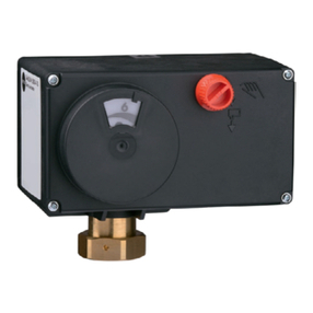
Type 3375 Electric Actuator
Version with positioner
Denition of signal words
Hazardous situations which, if not avoided,
will result in death or serious injury
Hazardous situations which, if not avoided,
could result in death or serious injury
Property damage message or malfunction
Additional information
Recommended action
DANGER
!
WARNING
!
NOTICE
!
Note
Tip
EB 8332-2 EN
Note on these mounting and operating instructions
These mounting and operating instructions assist you in mounting and operating the device
safely. The instructions are binding for handling SAMSON devices. The images shown in
these instructions are for illustration purposes only. The actual product may vary.
ÎFor the safe and proper use of these instructions, read them carefully and keep them for
later reference.
ÎIf you have any questions about these instructions, contact SAMSON‘s After-sales Service
(aftersalesservice@samsongroup.com).
The mounting and operating instructions for the devices are included
in the scope of delivery. The latest documentation is available on our
website at www.samsongroup.com > Service & Support > Downloads >
Documentation.
Contents
EB 8332-2 EN
1 Safety instructions and measures ................................................................1-1
1.1 Notes on possible severe personal injury ......................................................1-4
1.2 Notes on possible personal injury ................................................................1-4
1.3 Notes on possible property damage.............................................................1-5
2 Markings on the device ..............................................................................2-1
2.1 Nameplate .................................................................................................2-1
2.2 Firmware versions.......................................................................................2-2
3 Design and principle of operation ...............................................................3-1
3.1 Fail-safe action ...........................................................................................3-1
3.2 Communication ..........................................................................................3-1
3.3 Versions .....................................................................................................3-2
3.3.1 Standard version.........................................................................................3-2
3.3.2 Version with three-key operation ..................................................................3-2
3.4 Additional equipment..................................................................................3-2
3.5 Technical data ............................................................................................3-5
3.6 Dimensions in mm.......................................................................................3-8
4 Shipment and on-site transport ...................................................................4-1
4.1 Accepting the delivered goods .....................................................................4-1
4.2 Removing the packaging from the actuator ...................................................4-1
4.3 Transporting the actuator.............................................................................4-1
4.4 Lifting the actuator ......................................................................................4-1
4.5 Storing the actuator.....................................................................................4-2
5 Installation.................................................................................................5-1
5.1 Installation conditions..................................................................................5-1
5.2 Preparation for installation...........................................................................5-2
5.3 Mounting the actuator .................................................................................5-2
5.4 Retrottinglimitcontacts ..............................................................................5-3
5.5 Retrottingelectroniclimitcontacts ...............................................................5-7
5.6 RetrottingRS-485module ..........................................................................5-7
5.7 Electrical connection....................................................................................5-8
5.7.1 Connection (standard version)......................................................................5-8
5.7.2 Connection of version with three-key operation............................................5-14
6 Operation..................................................................................................6-1
6.1 Device overview and operating controls........................................................6-1
6.1.1 Display ......................................................................................................6-2
6.1.2 Rotary pushbutton.......................................................................................6-4
6.1.3 Keys on version with three-key operation ......................................................6-4
Contents
EB 8332-2 EN
7 Start-upandconguration..........................................................................7-1
7.1 Initializing the actuator................................................................................7-1
7.2 Conguringtheactuator..............................................................................7-2
7.2.1 Fastcongurationlevel................................................................................7-3
7.3 Selecting the application..............................................................................7-6
7.4 Adjusting the limit contacts ..........................................................................7-8
7.5 Setting up communication..........................................................................7-10
7.5.1 Serial interface .........................................................................................7-10
7.5.2 Modbus RTU module.................................................................................7-11
8 Setup.........................................................................................................8-1
8.1 Automatic mode .........................................................................................8-1
8.1.1 Information level .........................................................................................8-1
8.1.2 Operating level...........................................................................................8-2
8.1.2.1 Selecting the operating mode.......................................................................8-2
8.1.2.2 Determining the reading direction ................................................................8-2
8.1.2.3 Switching on the backlight...........................................................................8-3
8.2 Manual mode.............................................................................................8-4
8.2.1 Mechanical override ...................................................................................8-4
8.2.2 MAN mode................................................................................................8-6
8.3 Operation using memory pen ......................................................................8-7
8.3.1 Memory and data logging function ..............................................................8-7
8.3.2 Command function......................................................................................8-8
8.4 Service mode..............................................................................................8-9
8.4.1 Zero calibration ........................................................................................8-10
8.4.2 Initializing the actuator..............................................................................8-11
8.4.3 Restarting the actuator (reset).....................................................................8-11
8.4.4 Loading the default settings........................................................................8-12
8.4.5 Testing the display.....................................................................................8-12
8.4.6 Measuring the transit time..........................................................................8-13
9 Malfunctions ..............................................................................................9-1
9.1 Troubleshooting ..........................................................................................9-1
9.1.1 Error messages ...........................................................................................9-1
9.1.2 Other malfunctions or errors ........................................................................9-5
9.2 Emergency action .......................................................................................9-5
10 Servicing..................................................................................................10-1
11 Decommissioning .....................................................................................11-1
12 Removal ..................................................................................................12-1
13 Repairs ....................................................................................................13-1
Contents
EB 8332-2 EN
13.1 Returning the actuator to SAMSON............................................................13-1
14 Disposal...................................................................................................14-1
15 Certicates...............................................................................................15-1
16 AnnexA(congurationinstructions)..........................................................16-1
16.1 Key number..............................................................................................16-1
16.2 Input signal ..............................................................................................16-2
16.3 Direction of action.....................................................................................16-4
16.4 End position guiding .................................................................................16-5
16.5 Position feedback signal ............................................................................16-6
16.6 Binary input .............................................................................................16-6
16.7 Binary output............................................................................................16-7
16.8 Electronic limit contacts..............................................................................16-8
16.9 Restart .....................................................................................................16-9
16.10 Blockage ................................................................................................16-10
16.11 Travel.....................................................................................................16-11
16.12 Characteristic .........................................................................................16-12
16.13 Applications ...........................................................................................16-14
16.14 Levels and parameters.............................................................................16-15
16.14.1 Information level .....................................................................................16-15
16.14.2 Operating level.......................................................................................16-17
16.14.3 Service level ...........................................................................................16-18
16.14.4 Communication level...............................................................................16-20
16.14.5 Congurationlevel..................................................................................16-21
16.15 Further codes on the display ....................................................................16-27
16.16 Excerpt from Modbus data point list .........................................................16-27
17 Annex B...................................................................................................17-1
17.1 Partsforretrottingandaccessories............................................................17-1
17.2 After-sales service.....................................................................................17-2
Contents
EB 8332-2 EN
EB 8332-2 EN 1-1
Safety instructions and measures
1 Safety instructions and measures
Intended use
TheType3375ElectricActuatorisdesignedtooperateamountedglobevalveusedinindus-
trial applications as well as in heating, ventilation and air-conditioning systems. The digital
positioner ensures a predetermined assignment of the valve position to the input signal. The
actuatorisdesignedtooperateunderexactlydenedconditions(e.g.thrust,travel).There-
fore, operators must ensure that the actuator is only used in operating conditions that meet
thespecicationsusedforsizingtheactuatorattheorderingstage.Incaseoperatorsintend
tousetheactuatorinotherapplicationsorconditionsthanspecied,contactSAMSON.
SAMSON does not assume any liability for damage resulting from the failure to use the de-
vice for its intended purpose or for damage caused by external forces or any other external
factors.
ÎRefertothetechnicaldataforlimitsandeldsofapplicationaswellaspossibleuses(see
'Technical data').
Reasonably foreseeable misuse
The actuator is not suitable for the following applications:
−Useoutsidethelimitsdenedduringsizingandbythetechnicaldata
Furthermore, the following activities do not comply with the intended use:
−Use of non-original spare parts
−Performing service and repair work not described
Qualicationsofoperatingpersonnel
The actuator must be mounted, started up, serviced and repaired by fully trained and quali-
edpersonnelonly;theacceptedindustrycodesandpracticesmustbeobserved.According
to these mounting and operating instructions, trained personnel refers to individuals who are
able to judge the work they are assigned to and recognize possible hazards due to their spe-
cialized training, their knowledge and experience as well as their knowledge of the applica-
ble standards.
1-2 EB 8332-2 EN
Safety instructions and measures
Personal protective equipment
No personal protective equipment is required for the direct handling of the electric actuator.
Work on the control valve may be necessary when mounting or removing the device.
ÎObservetherequirementsforpersonalprotectiveequipmentspeciedinthevalvedocu-
mentation.
ÎCheck with the plant operator for details on further protective equipment.
Revisionsandothermodications
Revisions,conversionsorothermodicationsoftheproductarenotauthorizedbySAMSON.
They are performed at the user's own risk and may lead to safety hazards, for example. Fur-
thermore, the product may no longer meet the requirements for its intended use.
Safety features
The actuator has a thermal fuse which protects the asynchronous motor. The limit switches
automatically switch off the motor in the end positions. In actuators with fail-safe action, the
actuatorstemmovestoadenedendpositionuponsupplyvoltagefailure.Thefail-safeac-
tionofSAMSONactuatorsisspeciedontheactuatornameplate.
Warning against residual hazards
To avoid personal injury or property damage, plant operators and operating personnel must
prevent hazards that could be caused in the control valve by the process medium, the operat-
ing pressure, the signal pressure or by moving parts by taking appropriate precautions. Plant
operators and operating personnel must observe all hazard statements, warning and caution
notes in these mounting and operating instructions, especially for installation, start-up and
service work.
Responsibilities of the operator
Operators are responsible for proper use and compliance with the safety regulations. Opera-
tors are obliged to provide these mounting and operating instructions to the operating per-
sonnel and to instruct them in proper operation. Furthermore, operators must ensure that op-
erating personnel or third parties are not exposed to any danger.
EB 8332-2 EN 1-3
Safety instructions and measures
Responsibilities of operating personnel
Operating personnel must read and understand these mounting and operating instructions as
wellasthespeciedhazardstatements,warningandcautionnotes.Furthermore,theoperat-
ing personnel must be familiar with the applicable health, safety and accident prevention
regulations and comply with them.
Referenced standards, directives and regulations
TheType3375ElectricActuatorfulllstherequirementsoftheDirectives2014/30/EUand
2014/35/EU.Thedeclarationofconformityincludesinformationabouttheappliedconfor-
mity assessment procedure. This declaration of conformity is included in the annex of these
instructions.
TheType3375ElectricActuatorisdesignedforuseinlowvoltageinstallations.
ÎFor wiring, maintenance and repair, observe the relevant safety regulations.
Referenced documentation
The following documents apply in addition to these mounting and operating instructions:
−Mounting and operating instructions of the valve on which the electric actuator is mount-
ed, e.g. for SAMSON valves:
uEB5861forType3260Three-wayValve
uEB5868-1forType3214GlobeValvebalancedbyadiaphragm
uEB8012forType3241GlobeValve,ANSIandJISversion
uEB8015forType3241GlobeValve,DINversion
uEB8026forType3244Three-wayValve
uEB8051forType3251GlobeValve,DINversion
uEB8052forType3251GlobeValve,ANSIversion
1-4 EB 8332-2 EN
Safety instructions and measures
1.1 Notes on possible severe personal injury
DANGER
!
Risk of fatal injury due to electric shock.
ÎBefore connecting wiring, performing any work on the device or opening the de-
vice, disconnect the supply voltage and protect it against unintentional reconnec-
tion.
ÎOnly use power interruption devices that can be protected against unintentional re-
connection of the power supply.
ÎDo not remove any covers to perform adjustment work on live parts.
Risk of bursting in pressure equipment.
Valves and pipelines are pressure equipment. Improper opening can lead to valve
components bursting.
ÎBefore starting any work on the control valve, depressurize all plant sections affect-
ed as well as the valve.
ÎDrain the process medium from all the plant sections affected and from the valve.
ÎWear recommended personal protective equipment (see associated valve docu-
mentation).
1.2 Notes on possible personal injury
WARNING
!
Crush hazard arising from moving parts.
The electric actuator contains moving parts (actuator and plug stems), which can injure
handsorngersifinsertedintotheactuator.
ÎDonotinserthandsorngerintotheyokewhilethevalveisinoperation.
ÎDisconnect the supply voltage and protect it against unintentional reconnection be-
fore performing any work on the control valve.
ÎDo not impede the movement of the actuator or plug stem by inserting objects into
their path.
EB 8332-2 EN 1-5
Safety instructions and measures
WARNING
!
Risk of personal injury through incorrect operation, use or installation as a result of
information on the actuator being illegible.
Over time, markings, labels and nameplates on the actuator may become covered with
dirt or become illegible in some other way. As a result, hazards may go unnoticed and
the necessary instructions not followed. There is a risk of personal injury.
ÎKeep all relevant markings and inscriptions on the device in a constantly legible
state.
ÎImmediately renew damaged, missing or incorrect nameplates or labels.
1.3 Notes on possible property damage
NOTICE
!
Risk of damage to the electric actuator due to the supply voltage exceeding the per-
missible tolerances.
TheType3375ElectricActuatorisdesignedforuseaccordingtoregulationsfor
low-voltage installations.
ÎObserve the permissible tolerances of the supply voltage.
Risk of actuator damage due to excessively high tightening torques.
ObservethespeciedtorqueswhentighteningthemountingpartsofType3375Electric
Actuators. Excessive tightening torques lead to parts wearing out more quickly.
ÎObservethespeciedtighteningtorques.
Risk of damage to the electric actuator due to incorrect operation of the manual over-
ride.
The actuator stem of the electric actuator without fail-safe action can be adjusted manu-
ally.
ÎDo not operate the manual override while the actuator is in operation or while the
voltage supply is still connected.
Risk of actuator damage due to incorrect wiring of the binary inputs.
ÎAlwayswirethebinaryinputsasoatingcontacts.
1-6 EB 8332-2 EN
EB 8332-2 EN 2-1
Markings on the device
2 Markings on the device
2.1 Nameplate
SAMSON 3375-
1
13
3
2
4
5
67
11
8
9
12
Electric Actuator
Var.-ID
Serial no.
Firmware:
Digital Positioner
SAMSON AG, Germany
0(4) ... 20 mA DC; R
i
= 50 Ω
0(2) ... 10 V DC; R
i
= 20 kΩ
U:
Pmax:
s: v:
F
F
0062
Made in Germany
10
1 Type
2 CongurationID
3 Serial number
4 Supplyvoltage;powerlinefrequency
5 Power consumption
6 Rated travel
7 Stroking speed
8 Thrust (actuator stem retracts)
9 Thrust (stem extends)
10 Fail-safe action
Extends
Retracts
11 Firmware version
12 Limit contacts
Mechanical limit contacts
Electronic limit contacts
13 Year
2-2 EB 8332-2 EN
Markings on the device
2.2 Firmware versions
Firmware revisions
Old New
3.10 3.11
(internal revisions)
3.11 3.12
Baud rate 38400 is no longer available for Modbus.
Communication parameters can only be changed after the key number has been entered.
Special version with three-key operation is available.
The actuator version with three-key operation allows the set point to be changed and dis-
played on the start screen in "PID controller" and "Temperature closed-loop control upon in-
put signal failure" applications. The key number does not need to be entered beforehand in
this case.
Extended temperature measurement:
In the "PID controller" application, temperatures can be additionally measured using a
Pt1000sensoratinput1andinput2.TheCodec85(unit)mustbesetto"°C"andCode
c01(source)to"Pt1000input".Themeasuringrangehasaxedrange(–50°Cto
+150°C).ThemeasuredvaluescanonlybereadovertwoModbusholdingregistersand
not processed any further in the actuator.
EB 8332-2 EN 3-1
Design and principle of operation
3 Design and principle of oper-
ation
TheType3375ElectricActuatorisusedin
industrial plants as well as in heating, venti-
lation and air-conditioning systems.
This linear actuator is particularly suitable,
depending on whether the version is with or
without fail-safe action, for attachment to
SAMSONSeries240and250Valvesas
wellastoType3260Valve(DN200,250
and300)andType3214Valve(DN300
and 400).
The actuator can be used for various types of
control(seethe'Start-upandconguration'
section).
Principle of operation
The electric actuator consists of a reversible
asynchronous motor and a maintenance-free
planetary gear with ball screw drive. The ac-
tuator is switched off by torque-dependent
limit contacts. Additionally, the asynchro-
nous motor is protected by a thermal fuse.
3.1 Fail-safe action
The actuator versions with fail-safe action
contain a spring mechanism and an electro-
magnet. The actuator is moved by the force
of the spring to the fail-safe position when
the electromagnet (terminals L and N) is
de-energized. The direction of action de-
pends on the actuator version and cannot be
reversed.
3.2 Communication
Serial interface
TheactuatoristtedwithanRS-232serial
interface as standard. This allows communi-
cation with TROVIS-VIEW using SSP proto-
col.
The actuator can also be tted with an op-
tional RS-485 module (see the 'Installation'
section).
Conguration
Theactuatorcanbeconguredwiththe
TROVIS-VIEW software. In this case, the seri-
al interface on the actuator is used to con-
nect the actuator to the computer.
The TROVIS-VIEW software enables the user
toeasilycongurethepositioneraswellas
view process parameters online.
TROVIS-VIEW can be downloaded free of
charge from our website at
uwww.samsongroup.com > Service &
Support > Downloads > TROVIS-VIEW.
Further information on TROVIS-VIEW (e.g.
system requirements) is available on our
website and in the Data Sheet uT6661 as
well as the Operating Instructions
uEB6661.
ÎSeethe'Start-upandconguration'sec-
tion.
Note
Note
3-2 EB 8332-2 EN
Design and principle of operation
3.3 Versions
3.3.1 Standard version
The operating controls are located under-
neaththehousingcover(seeFig.3-2).
3.3.2 Version with three-key
operation
In the special version of the actuator with
three-key operation, the actuator is not oper-
ated using the rotary pushbutton. Instead,
three keys on the cover are used for opera-
tion(seeFig.3-1).
This actuator version can be operated with-
out having to remove the housing cover.
Fig.3-1: Housing cover of special version with
three-key operation
3.4 Additional equipment
Mechanical limit contacts
The two mechanical limit contacts consist of
two changeover switches. Their switching po-
sitions are changed independently from one
another by continuously adjustable cam disks.
Theoatingcontactscanbeusedaseither
makeorbreakcontactstoinuencethetasks
of control equipment.
The installation and adjustment of the me-
chanical limit contacts is described in the 'In-
stallation' section.
EB 8332-2 EN 3-3
Design and principle of operation
1
2
1 Rotary pushbutton
2 Display
3 Serial interface
4 Handwheel
4
3
Fig.3-2: Operating controls (with housing cover removed)
3-4 EB 8332-2 EN
Design and principle of operation
Electronic limit contacts
The two electronic limit contacts consist of re-
layswithchangeovercontacts.Theoating
contacts can be used as either make or break
contactstoinuencethetasksofcontrol
equipment.
In contrast to the mechanical limit contacts,
the electronic limit contacts no longer function
after a supply voltage failure. The relays are
de-energized and the contacts change to the
idle state.
The installation of the electronic limit contacts
is described in the 'Installation' section. Their
adjustment is described in the 'Start-up and
conguration'section.
The electronic limit contact can be triggered
by the actuator stem position exceeding or
falling below an adjustable switching point.
− Triggered when the position exceeds
theswitchingpoint: The limit contact is
activated when the actuator stem position
moves beyond the switching point. The
limit contact is deactivated when the ac-
tuator stem moves below the switching
point plus 'Hysteresis'.
− Triggered when the position moves be-
lowtheswitchingpoint: The limit contact
is activated when the actuator stem posi-
tion moves below the 'Switching point'.
The limit contact is deactivated when the
actuator stem position moves beyond the
switching point plus 'Hysteresis'.
An activated limit contact remains perma-
nently active if the switching point is smaller
or larger than the hysteresis. This limit con-
tact can only be deactivated by a restart (see
the 'Operation' section) or by resetting to
'NONE' (c24, c27).
RS-485 module
The RS-485 module allows the actuator to be
connected to a control station. Various com-
munications protocol (SSP or Modbus RTU
slave) are used for various functions. The RS-
485 module is required for Modbus RTU
communication.
ÎExcerptfromModbuslist:seeAnnexA.
Note
EB 8332-2 EN 3-5
Design and principle of operation
3.5 Technical data
Table3-1: Technical data · Actuator
Type3375 -10 -11 -20 -21 -22 -30 -31
Fail-safe action Without Actuator stem
extends
Actuator stem
retracts
Attachment(form-t) M30x1.5 M60x1.5 M30x1.5 M60x1.5 M30x1.5 M30x1.5 M60x1.5
Rated travel mm 30 60 30 60 30 30 60
Limited travel range Between10and100%oftheratedtravel
Handwheel Handwheel • • –––––
Electric • • • • • • •
Electrical connection
Supply voltage 230V,50to60Hz
Duty type S3-50%ED(1200c/h)accordingtoIEC60034-1
Power consumption VA 180 180 185 185 185 185 185
Transit time in s for rated travel
50Hz 50 100 50 100 50 50 100
60Hz 42 84 42 84 42 42 84
In the event of fail-safe action (approx.) – – 35 80 40 40 90
Stroking speed in mm/s
50Hz 0.6 0.6 0.6 0.6 0.6 0.6 0.6
60Hz 0.7 0.7 0.7 0.7 0.7 0.7 0.7
In the event of fail-safe action (approx.) – – 0.86 0.75 0.75 0.75 0.67
Thrust in kN
Extends 12.5 12.5 7.5 5 4 4 4
Retracts 12.5 12.5 1 1 4 4 2.5
Weight [kg]
Approx. 11.7 14.5 19.5 22.5 18 18 21
3-6 EB 8332-2 EN
Design and principle of operation
Type3375 -10 -11 -20 -21 -22 -30 -31
Device safety
Degree of protection IP65accordingtoEN60529,suspendedmountingnotper-
mittedaccordingtoEN60664
Class of protection IaccordingtoEN61140
Device safety According to EN 61010-1
Noise immunity AccordingtoEN61000-6-2andEN61326-1
Noise emission AccordingtoEN61000-6-3andEN61326-1
Conformity
Additional electrical equipment
Limit contacts
Mechanical Twoadjustablelimitcontactswithchangeoverswitches;
230VAC/1A·Withoutcontactprotection
Electronic Two adjustable limit contacts with relay and changeover
switches;
230VAC/1A·Withoutcontactprotection
RS-485 module
Module for Modbus RTU communication
Materials
Housing Bottom section Spheroidal graphite iron
Middle section Cast aluminum alloy
Motor housing Cast aluminum alloy
Fan guard Plastic
Cover Glass-ber-reinforcedplastic
Actuator stem Stainless steel
Other information
Motor switch-off By torque-dependent limit switches
Permissible temperature
ranges2)
Ambient 5to60°C
Storage –20to+70°C
Humidity 5to95%relativeairhumidity,nodewformation
1) Manual override is not possible in actuators with fail-safe action upon fail-safe action.
2) The permissible medium temperature depends on the valve on which the electric actuator is mounted. The limits in
the valve documentation apply.

Other Samson Controllers manuals

Samson EB 2090 User manual

Samson

Samson EB 2090 User manual

Samson 3275A Service manual

Samson

Samson 3275A Service manual

Samson 46-5 Service manual

Samson

Samson 46-5 Service manual

Samson TROVIS 5500 Service manual

Samson

Samson TROVIS 5500 Service manual

Samson 3372 Service manual

Samson

Samson 3372 Service manual

Samson 45-9 Service manual

Samson

Samson 45-9 Service manual

Samson 2371-10 Service manual

Samson

Samson 2371-10 Service manual

Samson series 43 Service manual

Samson

Samson series 43 Service manual

Samson series 43 Service manual

Samson

Samson series 43 Service manual

Samson 2357-3 Service manual

Samson

Samson 2357-3 Service manual

Samson 2488 N Service manual

Samson

Samson 2488 N Service manual

Samson TROVIS 5724-8 Service manual

Samson

Samson TROVIS 5724-8 Service manual

Samson TROVIS 5757-3 Service manual

Samson

Samson TROVIS 5757-3 Service manual

Samson TROVIS 5579 Service manual

Samson

Samson TROVIS 5579 Service manual

Samson TROVIS 5433 User manual

Samson

Samson TROVIS 5433 User manual

Samson 2357-3 Service manual

Samson

Samson 2357-3 Service manual

Samson 43-1 Service manual

Samson

Samson 43-1 Service manual

Samson 3301 Service manual

Samson

Samson 3301 Service manual

Samson 3374 Service manual

Samson

Samson 3374 Service manual

Samson 3271 Service manual

Samson

Samson 3271 Service manual

Samson 3730-4 User manual

Samson

Samson 3730-4 User manual

Samson TROVIS 5578-E Setup guide

Samson

Samson TROVIS 5578-E Setup guide

Samson 3375-10 Setup guide

Samson

Samson 3375-10 Setup guide

Samson Trovis 6400 Service manual

Samson

Samson Trovis 6400 Service manual

Popular Controllers manuals by other brands

HANYOUNG NUX TPR-3N instruction manual

HANYOUNG NUX

HANYOUNG NUX TPR-3N instruction manual

Gauzy LC6 FLEX Controller Installation and operation guide

Gauzy

Gauzy LC6 FLEX Controller Installation and operation guide

Master WiSlide 750 KG User and installation manual

Master

Master WiSlide 750 KG User and installation manual

Adaptec ICP 5045BL install guide

Adaptec

Adaptec ICP 5045BL install guide

Airflow Uno hab Installation and operating instructions

Airflow

Airflow Uno hab Installation and operating instructions

Emerson SW93 owner's manual

Emerson

Emerson SW93 owner's manual

Leica CS10 user manual

Leica

Leica CS10 user manual

THORLABS LDC40 Series Programmer's reference guide

THORLABS

THORLABS LDC40 Series Programmer's reference guide

National Instruments NI SMD-7613 user manual

National Instruments

National Instruments NI SMD-7613 user manual

THORLABS BSC103 user guide

THORLABS

THORLABS BSC103 user guide

Honeywell HC900 installation and replacement

Honeywell

Honeywell HC900 installation and replacement

Sentera STR-4 series Mounting and operating instructions

Sentera

Sentera STR-4 series Mounting and operating instructions

ACS contsys MIR-491 operating instructions

ACS contsys

ACS contsys MIR-491 operating instructions

Seg System A2 H15 General information

Seg

Seg System A2 H15 General information

Exalto CT3N user manual

Exalto

Exalto CT3N user manual

Mach M20.06 user manual

Mach

Mach M20.06 user manual

Carel ir33+ quick start guide

Carel

Carel ir33+ quick start guide

Nemtek SOL-REG140 user manual

Nemtek

Nemtek SOL-REG140 user manual

manuals.online logo
manuals.online logoBrands
  • About & Mission
  • Contact us
  • Privacy Policy
  • Terms and Conditions

Copyright 2025 Manuals.Online. All Rights Reserved.