Bergey VCSII User manual

Rev: 0 June 17, 2016
VCSII – Battery Charger
Bergey WindPower Co.
Owner’s Manual

Rev: 0 June 17, 2016
Table of Contents
Important Safety Instructions .................................................................................................................... 3
VCS II Mounting ........................................................................................................................................... 4
VCS II User Interface .................................................................................................................................... 6
VCS II User Configuration ............................................................................................................................ 7
VCS II Can Bus Interface ............................................................................................................................ 12
VCS II CAN Bus Message Specification ................................................................................................. 12
VCS II Status, Faults, & Warnings ................................................................................................................ 1
VCS II Fault List ........................................................................................................................................ 16
VCS II Warning List ................................................................................................................................... 17
VCS II Specifications..................................................................................................................................... 18
Turbine Input ........................................................................................................................................... 18
Battery Output ........................................................................................................................................ 18
Environmental ......................................................................................................................................... 18
Performance ............................................................................................................................................ 19

VCS II User Guide – Bergey WindPower Co.
Rev: 0 June 17, 2016 3
Important Safety Instructions
This manual contains important information concerning the installation of your VCSII. We strongly
recommend that you read and familiarize yourself with its contents.
At several points in this manual, items of special interest or significant impact are highlighted by one of
the following symbols:
DAN ER: Hazard or unsafe practice that could cause personal injury or death.
WARNIN : Hazard or unsafe practice which could cause product damage.
SAVE THESE INSTRUCTIONS
This manual contains important instructions for the VCSII that shall be followed during installation and
maintenance of the converter.
The output field wiring terminal (Battery) can be used for connection of a maximum of:
One 3 0MCM wire per terminal (1 wire for each line)
The input field wiring terminal (Turbine) can be used for connection of a maximum of:
One 2 AWG wire per terminal (1 wire per phase per terminal provided).
The field
-
wiring terminals shall be connected using the following wire types:
Copper Conductors Only (Input Turbine connection)
Use No. 8 - 2 AWG, 7 °C copper wire only
Copper Conductors Only (Output Battery connection)
Use No. 6 – 3 0MCM, 7 °C copper wire only
The following symbols are used as markings on this product with the following me
anings:
Equipment grounding conductor –
This converter is intended for operation in an indoor NEMA 1 compatible environment having a maximum
ambient temperature of 40°C (104° F).
CAUTION
To reduce the risk of fire, connect only to a circuit provided with 200 amperes maximum branch-circuit
over-current protection in accordance with the National Electrical Code, ANSI/NFPA 70.
Hot surfaces – To reduce the risk of burns – Do not touch
The enclosure and the rear heatsink can exceed 70°C (1 0°F).
Note that the input and output circuits are isolated from the enclosure. In accordance with Clause 1 .2.1.1
of CAN/CSA-C22.2 No. 107.1, system grounding, when required by the Canadian Electrical Code, Part I, is
the responsibility of the installer.

VCS II User Guide – Bergey WindPower Co.
Rev: 0 June 17, 2016 4
VCS II Mounting
WARNIN : Confirm factory default settings are appropriate for you battery bank prior to
commissioning to avoid potential battery damage. See the “VCS II User
Configuration” section.
The internal portion of the enclosure is sealed with no need for ventilation. The heatsinks, breaker and
external inductors are re not sealed to the enclosure and results in a NEMA 1 rating. The bottom and
top of the enclosure needs at least 12” of clearance to allow for natural convection through the rear
heatsinks and inductors. Mount the enclosure indoors away from excess heat, vibration and moisture,
and as close to the battery bank as possible.
The mounting bracket must be secured to the wall before mounting the enclosure. The hardware to
mount the bracket is not included. There are three main mounting holes at the top of the bracket on 16”
centers and two holes at the bottom of the bracket. There are also 10 additional mounting holes at the
top that can be used if necessary. Make certain that the combined mounting screws used are capable of
holding the weight of 110 lb. ( 0 kg).

VCS II User Guide – Bergey WindPower Co.
Rev: 0 June 17, 2016
DAN ER: The unit is heavy. Use appropriate lifting methods.
WARNIN : Care must be used when lifting the enclosure to the mounting bracket to avoid any
contact with the inductors to prevent their damage.
To install the VCSII enclosure on the bracket, partially put the two top screws (M6x20) on both sides of
the enclosure. They will be used to hang the unit on the bracket. Carefully lift the enclosure placing close
attention to the rear magnetics so they are not damaged. Once the enclosure is hung, the bottom two
mounting bolts can be installed and all tightened (Torque to 4. N-m, 40in-lb).
Conduit enters the bottom of the enclosure through provided knockouts. Drilling extra holes into the
enclosure is not recommended. The turbine leads enter on the left side of the enclosure, while the
battery connections are on the right side.
WARNIN : Clearance is required all sides of the enclosure for proper cooling.
Clearance is required on all sides of the VCSII to ensure proper cooling by natural convection. Each side
of the enclosure requires at least 6 inches (1 0mm) of clearance and the top and bottom of the
enclosure requires a minimum of 12inches (300mm) to ensure a free flow of air through the rear
mounted heatsinks. The VCS II does not use nor require fans for cooling for normal operation. The door
is hinged on the bottom - ensure that there are no obstructions to the door opening.

VCS II User Guide – Bergey WindPower Co.
Rev: 0 June 17, 2016 6
VCS II User Interface
The charge controller user/operator control input interface consists of a single push button on the front
panel of the charge controller. The single push button performs different functions depending on the
controller system state and operating mode and the length of time that the button is pressed.
The user push button functions are defined as follows:
1) No press of the user push button:
a) If the charge controller is powered up and there are no faults, the charge controller will
automatically go to the Charging Mode. The charge controller will charge the batteries, and
then maintain the battery voltage at a specified float voltage.
2) Press and hold the user push button for more than 0. seconds and less than seconds:
a) If the charge controller is powered up and in the Charging Mode with no faults, the charge
controller will go to the Manual Idle Mode.
b) If the charge controller is powered up and in the Manual Idle Mode with no faults, the charge
controller will go to the Charging Mode.
c) If the charge controller is powered up and in a Fault State, the charge controller will clear the
faults and go to the Charging Mode.
d) If the charge controller is powered up and in the Equalize Mode with no faults, the charge
controller will exit Equalize Mode and go to the Charging Mode.
3) Press and hold the user push button for more than seconds:
a) If the charge controller is powered up and in the Charging Mode with no faults, the charge
controller will go to the Equalize Mode for a predetermined time period. After Equalization, the
charge controller will go to normal charging mode, and will maintain the battery voltage at a
specified float voltage.

VCS II User Guide – Bergey WindPower Co.
Rev: 0 June 17, 2016 7
VCS II User Configuration
WARNIN : Confirm factory default settings are appropriate for you battery bank prior to
commissioning to avoid potential battery damage.
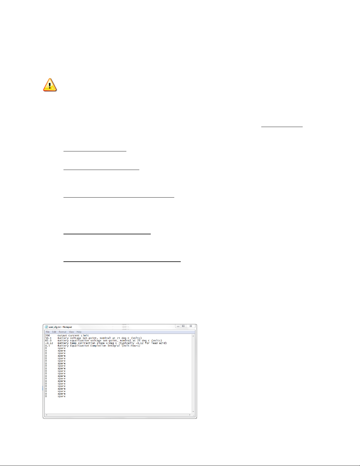
The VCS II user configurable parameters are stored on the SD card along with other files which should
not be altered without consultation of Bergey WindPower Co. The file user_cfg.txt is tab delimited and
allows setting all of the configuration settings. The file may be easily configured with any text file editor.
• “Output Current Limit”: [Adc], Factory default is “200”. This setting should not exceed 200
amps, but may be reduced to allow use with smaller battery banks.
• “Battery Voltage Set-point”: [Vdc], Factory default is “ 6.4”, for open celled lead acid
batteries. The voltage regulation is a constant voltage scheme, there are no bulk or float
settings.
• “Battery Equalization Voltage Set-point”: [Vdc], Factory default is “62.0”. The equalization
Voltage is settable, and if a battery temperature sensor is present, the equalization voltage is
temperature compensated. Equalization time is dependant on the “Battery Equalization
Completion Integral”.
• “Battery temp correction slope”: [Vdc/degC], Factory default is “-0.12”, for lead acid batteries.
Battery temperature compensation operates if an optional 10kΩ battery temperature sensor is
installed. There is only a slope correction vs temperature.
• “Battery Equalization Completion ntegral”: [V*hrs], Factory default is “0. ”, essentially
deactivating the equalization feature until the installer changes this value. Consult your battery
manufacturer. This value is defined as Volt*hours. For example at a setting of “4.0”, once
equalization is engaged, the batteries will be held above the nominal voltage either 1 volt for 4
hours, or 2 volts for 2 hours, etc. This allows for the intermittent nature of the wind, and as
soon as the totalized Volt*Hours are completed the controller will return to its normal Battery
Voltage Set-point.

VCS II User Guide – Bergey WindPower Co.
Rev: 0 June 17, 2016 8
There is a fault log stored on the SD card for all faults encountered- fltsxxxx.csv. The highest number
xxxx is the latest fault log. Basic data surrounding the fault are stored. Additionally there is high
resolution scope data files created during each fault. To avoid filling the SD card with too much data
there are only 10 detailed fault scope files stored. The files are overwritten in numerical order. To find
the last fault log file look in column Z for the scope file index (shown in yellow below).
Then find the scope_xx.csv that corresponds to that fault, in this case scope_03.csv. Keep in mind that
only scope logs for the last 10 faults are stored.
The scope fault logs show 16 channels of data surrounding the faults, with a 2 µs resolution. There are
2000 samples saved in each scope file. The channels which will be saved are selected from several
groups of data, which data group is saved is set in the last line in sysparam.txt (see below)
Sysparam.txt contains most of the tuning calibrations; do not change any values except History Logging
Interval or Data Capture Group. The history files are long term performance type data that are saved to
the SD Card. They are saved at 10 minute increments by default (not the 10 seconds shown below). The
Data Capture Group can be changed to help with fault diagnosis in case there are faults that require
different high resolution data to diagnose.

VCS II User Guide – Bergey WindPower Co.
Rev: 0 June 17, 2016 9

VCS II User Guide – Bergey WindPower Co.
Rev: 0 June 17, 2016 10
The long term data files are stored by default at 10 minute intervals; there is no real time clock in the
VCS II so the on time is stored in the first column, with the cumulative energy in kWh stored in the
second column. Snapshot data are also stored regarding battery voltage, current, and temperature. To
help with turbine and wiring diagnosis all 3 phase voltages, as well as the turbine frequency are stored.
The dataxxxx.csv files are the only place that cumulative kWh and run time are stored, so if the files are
deleted or modified an incorrect kWh or run time will be displayed.
All calibration data are stored in cal_data.txt, these values are determined for each unit during initial
testing. They should not need to be altered after initial calibration.

VCS II User Guide – Bergey WindPower Co.
Rev: 0 June 17, 2016 11
The power curve is stored as pwrcrv.csv, the format is frequency in column A and power in watts in
column B. The frequency must be given in 1 Hz increments up to 1 0 Hz. Changes to the power curve
should not be made without Bergey WindPower Co approval, as damage to the controller or the
alternator can occur if improper values are used.

VCS II User Guide – Bergey WindPower Co.
Rev: 0 June 17, 2016 12
VCS II Can Bus Interface
The CAN Bus utilizes an isolated input to provide a galvanic isolation rating of 2 00 V
RMS
. An RJ4
connection (CN20) is provided on the controller with a pinout of:
Pin 1 – NC
Pin 2 – NC
Pin 3 – V+
Pin 4 – CANH
Pin – CANL
Pin 6 – GND
Pin 7 – NC
Pin 8 - NC
VCS II CAN Bus Message Specification
1. The baud rate is fixed to 250k.
2. Little endian” is used for CAN transmission — least significant byte is
transmitted/received first.
3. Only standard identifier (11bit) is supported.
4. Message ID Specifications:
Message
ID
Request Response Comment
1 DLC: 1
Mailbox 0 is reserved
to receive this
message.
DLC: 1
Mailbox 16 is reserved
to echo back the
original message
This message is for command:
1 = Start (Reset), 0 = Stop.
• If the system is in regular charge
or equalizer mode, the Stop”
command will stop the system
operation.
• If the system is in stop mode, the
Start” command will start the
system.
• If the system is in fault state, the
Start(Reset” command will clear
the fault and prepare the system to
go to run state.
2 DLC: 4
Mailbox 1 is reserved
to receive this
message.
Data format: single
precision float.
DLC: 4
Mailbox 17 is reserved
to echo back the
original message.
Data format: single
precision float.
This message sets the battery
regulation voltage for normal
operation.

VCS II User Guide – Bergey WindPower Co.
Rev: 0 June 17, 2016 13
Message
ID
Request Response Comment
3 DLC: 4
Mailbox 2 is reserved
to receive this
message.
Data format: Uint32
DLC: 8
Mailbox 18 is reserved
to send the parameter
to external controller.
Data format: The first
4 bytes are Uint32.
The last 4 bytes are
float32 or Uint32,
depending on the data
item.
•
The external controller sends this
message to DSP to request certain
parameter. The parameter ID
(PID) is included in the requested
message.
• The DSP responds with the
parameter filled in the last 4 bytes
of the CAN message. The first 4
bytes still holds the PID.

VCS II User Guide – Bergey WindPower Co.
Rev: 0 June 17, 2016 14
5. Parameter ID Specifications:
Parameter ID
(PID)
Description Data
Type
0 High Limit battery voltage target allowed [Vdc] Float32
1 Lo Limit battery voltage target allowed [Vdc] Float32
2 Max output current limit allowed [Adc] Float32
3 Maximum Output Power (W) Float32
4 Hot Start Ramp Timer (s) Float32
5 Firmware revision [na] Float32
6
Equalize voltage reference [Vdc]
Float32
7
Battery temperature compensation [V/deg C]
Float32
8
VoltTime limit for Equalize mode [Vhr]
Float32
9
Regulation voltage reference [Vdc]
Float32
10 Energy(kWh) Float32
11
Average battery voltage measured [Vdc]
Float32
12
Average output current measured [Adc]
Float32
13
Average battery temp measured [deg C]
Float32
14
Average heatsink temp measured [deg C]
Float32
15
L1-L2 voltage [Vac,rms]
Float32
16
L2-L3 voltage [Vac,rms]
Float32
17
L3-L1 voltage [Vac,rms]
Float32
18
Turbine frequency measured [Hz]
Float32
19
System state [na]
Uint32
20
Average current measured, chopper 1 [Adc]
Float32
21
Average current measured, chopper 2 [Adc]
Float32
22
Average current measured, chopper 3 [Adc]
Float32
23
Average current measured, chopper 4 [Adc]
Float32
24
Average current measured, chopper [Adc]
Float32
25
Average current measured, chopper 6 [Adc]
Float32
26
Average current measured, chopper 7 [Adc]
Float32
27
Average current measured, chopper 8 [Adc]
Float32
28
Software current reference [Adc]
Float32
29
Bus voltage measured [Vdc]
Float32
30
Present fault state[na]
Uint32
31
Last fault state cleared
Uint32
32
Warnings [na]
Uint32
33
Reserved
34
Reserve
d
35
Reserve
d
36
Reserve
d
37
Reserve
d
38
Reserve
d

VCS II User Guide – Bergey WindPower Co.
Rev: 0 June 17, 2016 1
VCS II Status, Faults, & Warnings
The faults and warning messages are basically coded as binary bits, such that multiple faults and
warnings can be transmitted. There will be an integer value returned for fault and warning
queries. This can be converted to hex and looked up in the tables on the following pages, or if
converted to binary then each individual bit indicates a separate fault.
Status:
Low Wind Speed = Turbine is spinning too slow to generate power.

VCS II User Guide – Bergey WindPower Co.
Rev: 0 June 17, 2016 16
VCS II Fault List
Fault (PID 30 & 31) Hex Code
Fault, over current chopper 1 [na]
0x00000001
Fault, over current chopper 2 [na]
0x00000002
Fault, over current chopper 3 [na]
0x00000004
Fault, over current chopper 4 [na]
0x00000008
Fault, over curre
nt chopper [na]
0x00000010
Fault, over current chopper 6 [na]
0x00000020
Fault, over current chopper 7 [na]
0x00000040
Fault, over current chopper 8 [na]
0x00000080
Fault, De
-
saturation chopper 1 [na]
0x00000100
Fault, De
-
saturation chopper 2 [na]
0
x00000200
Fault, De
-
saturation chopper 3 [na]
0x00000400
Fault, De
-
saturation chopper 4 [na]
0x00000800
Fault, De
-
saturation chopper [na]
0x00001000
Fault, De
-
saturation chopper 6 [na]
0x00002000
Fault, De
-
saturation chopper 7 [na]
0x00004000
Fault
, De
-
saturation chopper 8 [na]
0x00008000
Fault, Battery Over Voltage Fault (Volts)
0x00010000
Fault, DC bus over voltage [na]
0x00020000
Fault, Logic Power Supply Over Voltage (Volts)
0x00040000
Fault, Logic Power Supply Under Voltage (Volts)
0x000800
00
Fault, battery over temp [na]
0x00100000
Fault, Heat sink over temp [na]
0x00200000
Fault, battery disconnect
0x00400000
Fault, Interrupt overrun [na]
0x00800000
Fault, alternator phase loss [na]
0x01000000
Fault, non
-
maskable interr
upt [na]
0x02000000
Fault, D V [na]
-
No parameter for this. Uses GPIO
0x04000000
Fault, PLL Sync
0x08000000
Fault, [EXCESS BUS CLAMPING]
0x10000000
Fault, Watchdog [na]
0x40000000

VCS II User Guide – Bergey WindPower Co.
Rev: 0 June 17, 2016 17
VCS II Warning List
Warning (PID 32) Hex Code
MS_OUTPUT_POWER
0x0
0000001
MS_BAT_FULL_CHARGED
0x00000002
MS_SD_MISSING
0x00000004
MS_THERMAL_ACTIVE
0x00000008
MS_CAN
_COMM_ERROR
0x00000010
MS_EQUALIZE_MODE
0x00000020
MS_SD_PROTECTED
0x00000040
MS_LOW_SPEED
0x00000080
MS_MANUAL_MODE
0x00000100
MS_BAT_V
OL_LOW
0x00000200
MS_BAT_TEMP_HIGH
0x00000400
MS_PHASE_ROTATION
0x00000800
MS_EXT_RAM_FAILED
0x00001000

VCS II User Guide – Bergey WindPower Co.
Rev: 0 June 17, 2016 18
VCS II Specifications
Turbine Input
Input current (max) 43 Amps
Input voltage (max) 480 Vrms
Input start voltage minimum (at low battery condition) 30 Vrms
Input normal operating voltage range 35 Vrms – 480 Vrms
Input frequency range 0 – 150 Hz
Cut-in frequency 15 Hz
Cut-out frequency 10 Hz
Battery Output
Rated output current (max) 200 Amps
Rated output voltage (max) 65 Vdc
Output start voltage minimum (at low battery condition) 36 Vdc
Output normal operating voltage range 40 – 63 Vdc
Control method Constant Voltage
Output overcurrent protection (DC Breaker) 250 Amps
Environmental
Enclosure type NEMA 1 / IP60 Overall
NEMA 3R / IP66 for
internal controls
Operating temperature range -20 to 40 °C
Max altitude 1000 m
Thermal derating (approximate ambient temperature) 45 °C
Thermal shutdown 80 °C
Weight 106 lb / 48kg

VCS II User Guide – Bergey WindPower Co.
Rev: 0 June 17, 2016 19
Performance
Rated power (11 m/s) 8 kW
Rated RPM 170
Rated windspeed 11 m/s
Start-up windspeed 4 m/s
Cut-in windspeed 1.8 m/s
Cut-out windspeed none
Furling windspeed 16-18 m/s
Max design windspeed 60 m/s
Table of contents