Beringer BP x4-MB User manual

Page 2 of 39
BERINGER Middle East FZC Fujairah Free Zone Phase III Fujairah, U. A. E
Phone: +971 9 277 48 51
Homepage: www.beringer-behaelter.com E-Mail: info-uae@beringer-behaelter.com
Table of contents
1. Safety instructions................................................................................................... 3
2. Description............................................................................................................... 6
2.1 Intended use.............................................................................................................. 6
2.2 Description of main parts ........................................................................................... 6
2.3 Additional options....................................................................................................... 6
2.4 Control Panels........................................................................................................... 7
2.5 Power Unit................................................................................................................. 7
2.6 Header....................................................................................................................... 8
2.7 Additional limit switch maintenance door.................................................................... 8
2.8 Interlock at cleanout door........................................................................................... 8
2.9 Tipping device............................................................................................................ 9
3. Set up and Operation............................................................................................... 9
3.1 Set up........................................................................................................................ 9
3.2 Initial operation ........................................................................................................ 10
3.3 Diagnostic fault-finding............................................................................................. 11
4. Service and Maintenance ...................................................................................... 12
4.1 Periodical Maintenance............................................................................................ 12
4.2 Electric System........................................................................................................ 14
5. Appendix ................................................................................................................ 14
5.1 Technical Data......................................................................................................... 14
5.2 Lubrication plan ....................................................................................................... 15
5.3 Hydraulic plan including parts list............................................................................. 16
5.4 Electronic plan......................................................................................................... 18
5.5 Damage Report ....................................................................................................... 21
5.6 User’s manual control panel..................................................................................... 24
5.7 Spare parts lists....................................................................................................... 34
5.8 Declaration of Conformity......................................................................................... 39

Page 3 of 39
BERINGER Middle East FZC Fujairah Free Zone Phase III Fujairah, U. A. E
Phone: +971 9 277 48 51
Homepage: www.beringer-behaelter.com E-Mail: info-uae@beringer-behaelter.com
1. Safety instructions
Important instructions concerning technical safety and security are highlighted with the following sign
1. Please read the user’s manual carefully before initial operation. Make sure you also read the additional
instructions for options of your reducer. The user’s manual has to be carried along with the reducer.
2. If the mobile reducer is located in public places (e.g. markets, schools, etc.) and is unsupervised, additional
safety measures respecting to individual case have to be made.
3. Only authorized persons are allowed to operate, maintain or repair the reducer.
4. Only employ qualified or trained staff and define clear competences for operation, service and repair works.
5. Allow the person in charge to defeat safety instructions of third persons.
6. Only train your staff on the reducer with experienced persons and under permanent surveillance.
7. Periodically check if your staff obeys to the safety instructions.
8. Wear safety garment while working at or on the reducer.
1) Avoid wearing rings, watches, ties, scarves, open jackets or loose fitting cloths. Those items carry
the risk to get stuck in the reducer.
2) For some works safety shoes, helmets and work gloves are compulsory.
3) Depending on the compacted material, the staff might need special safety equipment (e.g. ear plugs,
safety glasses).
9. Don’t use fire or candles in the surrounding of the reducer. Make yourself familiar with the location of
extinguishers and inform you about local institutions of fire protection.
10. For ergonomic reasons the employment of platforms can be reasonable. For platforms and their accesses,
the minimum carrying capacity has to be 3000 N/m³. The surface has to be levelled and free of rough
spots. At a height of more than 1 meter, a safety rail as to be adjusted. A platform can only be used at the
front side of the compactor.
11. If the mobile reducer is located at a ramp or in an underfloor bunker, safety rails have to be adjusted.
Ensure the free access to the emergency stop switch (eventually use a remote control).
12. The reducer has to be checked periodically –at least once a year –for workers’ safety.
BE AWARE: refers to work procedures
which have to be followed
in order to avoid dangers
for persons.
ATTENTION: refers to work procedures
in order to avoid damages
of the machine.

Page 4 of 39
BERINGER Middle East FZC Fujairah Free Zone Phase III Fujairah, U. A. E
Phone: +971 9 277 48 51
Homepage: www.beringer-behaelter.com E-Mail: info-uae@beringer-behaelter.com
13. To ensure before initial operation:
1) Before initial operation, the reducer has to be inspected by the operator. Don’t operate the reducer
before having made a proper inspection. Please especially check the labelling.
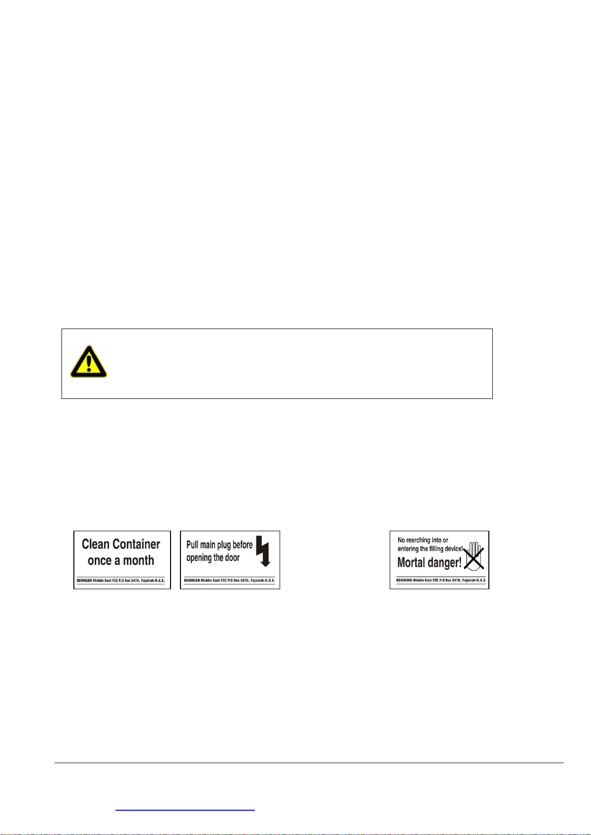
2) Please pay attention to all labels with danger and safety instructions.
3) Fix all loose parts on the machine.
4) All lids and cover panels have to be closed before initial operation and after maintenance works.
5) The interlock at the cleanout door has to be locked.
6) Make sure that nobody is working in or on the compactor.
7) During operation nobody is allowed to be in the sphere of the hydraulic jack / heading tool. Danger of
squeezing by pivoting cylinder!
Attention: Doors / Flaps have to be closed.
14. For special employment the reducer has to be equipped with specific safety devices. In this case only
operate the reducer if those are assembled and all maintenance doors are closed.
15. Inspection, maintenance and repair works (instruction p. 11)
1) For maintenance and repair works please proceed as described in the following:
(1) Switch off motor.
(2) Switch off main switch.
(3) The key at the key switch has to be taken off in 0-position.
(4) Plug off power cable.
(5) Main switch has to be locked with a padlock against switch on.
2) The system sections and pressure pipes of the hydraulic have to be at zero pressure before repair
works.
3) Make sure that all fixtures and protective shields against vibrations, abrasion and heat accumulation
are installed according to instructions.
4) The electric installation has to be inspected by an electrician. All damages like loose connections or
wore down cables should immediately be repaired by an expert.
5) Check in periodical intervals all cables, hydraulic hoses and hydraulic connections for leaks and
damages.
6) Hydraulic oil has to be changed in cooled down condition.
7) Never jump off the compactor. Use intended footstep, ladder or base to climb down.
16. Never operate a damaged compactor. Repair all damages immediately.
17. Cleaning the reducer:
1) Be aware while using wear parts and additives. Don’t use inflammable liquids.
2) All openings where no water should impinge during cleaning have to be closed, glued or removed.
Attention: Leaking oil can lead to fire. Wear work gloves while searching for leaks. The
hydraulic oil is hot when the reducer is close to operating temperature. Avoid
skin contact to hot oil or oil bearing parts.

Page 5 of 39
BERINGER Middle East FZC Fujairah Free Zone Phase III Fujairah, U. A. E
Phone: +971 9 277 48 51
Homepage: www.beringer-behaelter.com E-Mail: info-uae@beringer-behaelter.com
18. Transport of the reducer:
1) For transport of the mobile reducer, vehicles according to DIN 30723 (chain-loader-truck) are
appropriate. Make sure to comply with all regulations for load safety.
2) The position adaptor has to be in visual range or speaking contact to the driver.
3) The reducer always has to be picked up in the manner that the shifting of weight doesn’t endanger
stability. Avoid steel-to-steel contact.
4) Use ramps or ladder while working overheads.
19. Don’t do any modifications on the reducer without permission of the supplier. This also means installation
of safety devices and –valves as well as welding on bearing components.
20. For safety reasons necessary functional sequences can’t be changed. Therefore it is not allowed to remove
or invalidate safety devices
21. For all flexible supply cables a heavy rubber hose pipe (H 07 RN-F according to VDE 0100) has to be used.
22. Never open the door if the reducer is partly filled. The door is under pre-stressing and opens abruptly.
Eventually the door can’t be closed again before emptying.
23. Long and bulky goods have to be inserted completely into the feed opening.
24. Labels on the reducer which indicate dangers
At the maintenance door of compacting unit at the ratchet lock
25. Generally, it is advisable to use only original spare parts of the manufacturer.
BE AWARE: Never grasp or step into the feed opening during operation!
MORTAL DANGER ! ! !

Page 6 of 39
BERINGER Middle East FZC Fujairah Free Zone Phase III Fujairah, U. A. E
Phone: +971 9 277 48 51
Homepage: www.beringer-behaelter.com E-Mail: info-uae@beringer-behaelter.com
2. DESCRIPTION
2.1 Intended use
The mobile reducer can be picked up with all change systems according to DIN 30723 (chain loader
trucks). The mobile reducer compacts consumer waste and commercial waste (e.g. paper, residual
waste, cartons). Never fill in sand, construction waste, stones, glass, hot ash, inflammables, acid or
base containing materials as well as heavy metal parts (e.g. hollow sections, beams) or wooden
beams. The reducer is not appropriate for operation in explosive areas (e. g. chemical factories).
2.2 Description of main parts
2.3 Additional options
- Lid for feed opening connected front sides or divided long sides
- Lid for feed opening divided long sides with aluminium crossbar or safety net
- Lid for feed opening divided long sides with control panel on lid
- BERINGER bin lifter; mobile or adjusted
- Mobile reducer; wet waste variation
- Container fill level warning
1
2
3
4
5
6
7
1 Power unit box
2 Lid; feed opening
3 High-voltage connection and control
panel
4 Brief instruction
5 Type label
6 Chain bolts
7 Interlock of cleanout door

Page 7 of 39
BERINGER Middle East FZC Fujairah Free Zone Phase III Fujairah, U. A. E
Phone: +971 9 277 48 51
Homepage: www.beringer-behaelter.com E-Mail: info-uae@beringer-behaelter.com
2.4 Control panels
1. Main switch; power supply ON / OFF.
2. Key switch; security against unauthorized use.
3. Light: 80 % fill level warning; if light flahes, compactor is filled 80 %.
4. Light dysfunction; motor-circuit switch F1 releases –reducer shuts down automatically.
5. Socket: to connect power supply cable with a CEE-plug.
6. Emergency stop push-button, by pressing this button, the ram plate stops in its current position and
persons can be rescued.
7. ON button, ON push-button starts the reducing process (keep button pressed for 3-5 sec.). With the
integrated time-lag relay the reducer accomplishes about three pressing cycles automatically. The ON-
button flashes during operation.
8. Emergency off push-button, by pressing the button the ram plate stops in its current position. Resetting
operation is only possible by unlocking the emergency stop push-button. By pressing ON, the ram plate
moves back to the retraced position.
2.5 Power unit
1 Motor with hydraulic pump
2 4/3 directional valve
3 Oil tank
4 Filling and breather filter
5 Manometer
6 Oil deficiency switch
7 Control box
2
3
4
5
4
6
7
1
3
4
5
4
6
8
7
2
1

Page 8 of 39
BERINGER Middle East FZC Fujairah Free Zone Phase III Fujairah, U. A. E
Phone: +971 9 277 48 51
Homepage: www.beringer-behaelter.com E-Mail: info-uae@beringer-behaelter.com
2.6 Header
Before the mobile reducer can be picked up with a chain-loader-truck, it has to be ensured that the hook
is in good condition (check for wearing down).
In the header, the ram plate is located, which is run by two hydraulic jacks. Those are installed
underneath the power unit box.
2.7 Additional limit switch at maintenance door
The maintenance door of the header is equipped with an additional limit switch. If the
maintenance door is open during the pressing cycle, the limit switch, switches off the reducer.
2.8 Interlock at cleanout door
BE AWARE!
Pull plug before opening the door and
secure against engaging.
Attention! Close door interlock with
ratchet and secure with
spring connector after each
emptying.

Page 9 of 39
BERINGER Middle East FZC Fujairah Free Zone Phase III Fujairah, U. A. E
Phone: +971 9 277 48 51
Homepage: www.beringer-behaelter.com E-Mail: info-uae@beringer-behaelter.com
2.9 Tipping device
3 SET UP AND OPERATION
3.1 Set up
BE AWARE!
Please read the following safety instructions and the ones in chapter 1 before set
up and obey to those!
1. The bearing capacity of the ground at reducer’s location has to be at least 17.00 N/m³.
2. The reducer is not appropriate for operation in explosive areas. (e.g. chemical plants).
3. At reducer’s location has to be enough space for transport with a chain-loader-truck.
4. If the compactor is filled from a ramp or a platform, the height of the feed opening has to be at
least 1,10 meters above the ramp.
5. The ground has to be solid and levelled to avoid bracing of the reducer.
6. Provide enough light at reducer’s location.
7. The location should be protected against unauthorized access.
8. The electricity supply at location has to be protected with a fault current circuit breaker (F1 switch),
sensitive trigger of max. 30 mA and fuse protection min. 16 A delay. The feed cable has to have a lateral
cut of min. 4 x 2,5 mm² copper, 400 V 50 Hz, electricity network: TN –C –S, CEE plug, 16 A , fuse
protection with 3-pole breaker performance 3 x 16 A, characteristic C/D connected upstream with a fault
current circuit switch with max. 0,03 A release current.
9. For flexible supply cables a heavy rubber hose pipe HO/RN-F VDE 0100 has to be used.
BE AWARE! Ensure that the cleanout
door is closed and locked,
before starting the
pressing cycle.

Page 10 of 39
BERINGER Middle East FZC Fujairah Free Zone Phase III Fujairah, U. A. E
Phone: +971 9 277 48 51
Homepage: www.beringer-behaelter.com E-Mail: info-uae@beringer-behaelter.com
ATTENTION: During pressing cycles, the operating staff has to stay at the control
panel; to be able to stop the reducer in case of emergency. The staff
can only leave the control panel, if the key at the key switch was taken
off in 0 position.
3.2 Initial operation
The mobile compactor has been tested before delivery and is ready for operation after proper installation.
Before initial operation the following safety instructions have to be followed.
BE AWARE The operating staff has to be trained on handling and safety instructions of the mobile
reducer.
The compacting unit has to be closed.
The cleanout door has to be closed and locked.
No person is allowed to be in the filling device.
The maintenance door at the power unit box has to be closed during operation.
Adjust motor-circuit switch to nominal current and watch out for the rotary field (right).
1) CEE-plug has to be connected to the coupling mouth at the control panel.
2) Switch on main switch.
3) Unlock (by pulling) emergency OFF button.
4) Key switch has to be in position “I”
5) Press ON push-button for at least 3-5 sec. The mobile reducer accomplishes about 3 pressing cycles
and switches off automatically when the ram plate is in the retraced position.

Page 11 of 39
BERINGER Middle East FZC Fujairah Free Zone Phase III Fujairah, U. A. E
Phone: +971 9 277 48 51
Homepage: www.beringer-behaelter.com E-Mail: info-uae@beringer-behaelter.com
3.3 Diagnostic fault-finding
Disturbance
Reason
Solution
Machine is not functioning
Power supply
Check power supply network, switch
on main switch; unlock all
emergency OFF buttons; close
maintenance door of compacting
unit; check motor circuit switch F1 of
supply cable; check cable for leaks.
Motor runs; ram plate doesn’t
move
Insufficient hydraulic oil, oil
deficiency switch switches off the
reducer automatically, motor only
runs if ON button is pushed
Check hydraulic oil indicator; refill
hydraulic oil if necessary
Control valve failure
Call service staff
Hydraulic hoses and/or hydraulic
system leaky
Recover impermeability; call service
staff if necessary
Ram plate twists during operation
Loose ram plate guiding
Call service staff
Drawer leaves guiding
Call service staff
ATTENTION! If disturbances occur which can’t be repaired by the operating staff,
please call the manufacturer’s service staff.

Page 12 of 39
BERINGER Middle East FZC Fujairah Free Zone Phase III Fujairah, U. A. E
Phone: +971 9 277 48 51
Homepage: www.beringer-behaelter.com E-Mail: info-uae@beringer-behaelter.com
4. MAINTENANCE AND CLEANING
Generally we advise you to conclude a service contract with the manufacturer. Periodical inspections by an
expert ensure safety and a long life-time cycle of the compactor.
Please ask for a quotation concerning the service contract.
The maintenance contract includes the following yearly benefits:
•Visual inspection of external damages, door latches, notches
•Check of the control panel, plugs, feed cables
•Check of tube and hose cables, fittings
•Check of the cylinder and the hydraulic system
•Assessment and adjustment of the pressure
•Assessment of hydraulic gate and motor-circuit switch
•Assessment of the control box for condensation water
•Assessment of slide blocks and press ram
•Oil change/ filter change
•Lubricating and oiling
4.1 Periodical Maintenance
Check and correct the oil level
It is necessary to check the level of the hydraulic oil in periodic intervals especially after leakage or
maintenance work. After leakage or repair work, the reducer has to be operated unfilled for about 15
minutes in order to aerate the jacks. Afterwards the power unit has to be shut down for 6 hours to degas
the oil.
At the reducer´s front side (direction of heading; left) the oil level indicator and the drain cock are situated.
With the ram plate fully extended (piston rod of the cylinder fully extended), the oil level should be higher
than 10 mm above the minimum check mark.
The reducer switches off automatically if the oil level is too low, due to an installed oil deficiency switch.
ATTENTION Obey to the following safety instructions during maintenance work
including the safety Instructions in chapter 1
1. Switch off main switch, secure it against switch on with a
padlock, detach key and power cable (key has to be kept by
service staff)
2. Press all emergency OFF buttons
3. Don’t remove or invalidate safety devices
4. Calibrations of hydraulic panel are not to change (sealed). Only
use original spare parts of the manufacturer for the hydraulic
system.

Page 13 of 39
BERINGER Middle East FZC Fujairah Free Zone Phase III Fujairah, U. A. E
Phone: +971 9 277 48 51
Homepage: www.beringer-behaelter.com E-Mail: info-uae@beringer-behaelter.com
If hydraulic oil has to be refilled, the ram plate has to be extended fully to be positioned safely on the
drawer. Afterwards the power unit cover can be opened (remove 11pcs screws M8x20). The power unit
cover can be removed if required (the security chain´s snap hook is to be hung out and the cover is to be
pulled off the hinge side wards).
Unscrew the oil-filler neck (black synthetics, with covers) so hydraulic oil can be filled in with a cranked
hopper.
Oil change
After each 3000 operating hours –but at least once a year - it is necessary to conduct a change of
hydraulic oil and to change the return filter.
An appropriate tank has to be put beneath the drain cock and its cap has to be removed.
In the reducer´s power unit box a tube is situated, equipped with a cap nut R ½”, that is used to drain the
oil. Open the drain cock with a jaw wrench SW 12.
After finishing the maintenance work at the power unit the cap´s deal ring is to be positioned with a little
grease in the slot. Afterwards the cap can be assembled in reverse order. To avoid a turning of the clamp
bolt inside the tank the cap should be lifted a little bit.
Weekly
Check all parts of the hydraulic system for leaks
1. Clean return flow filter: open covering of power unit; loosen fixture screws of return flow filter, take out
return flow filter for cleaning.
2. Check oil indicator; refill hydraulic oil if necessary.
Check all electric cables for damages.
Quarterly
- Check hydraulic system for impermeability and oil level; lubricate ram plate guiding with multi-purpose
grease
- Lubricate grease nipples of rollers, hydraulic jack and door hinges with multi-purpose grease
Yearly
- Change hydraulic oil (HLP 32).
ATTENTION Maintenance work at the power unit can only be conducted, if the power unit is
cool.

Page 14 of 39
BERINGER Middle East FZC Fujairah Free Zone Phase III Fujairah, U. A. E
Phone: +971 9 277 48 51
Homepage: www.beringer-behaelter.com E-Mail: info-uae@beringer-behaelter.com
4.2 Electric system
Before opening the control box, detach system from electricity!
It is necessary to open the control box in case the red light “fault” glows. In this case the motor circuit switch “F1”
actuates (usually failure of motor power supply or motor is overloaded).
In the power unit box, the control box is situated next to the hydraulic power unit. By a left quarter turn of the
locking mechanism the clear cover can be removed.
After cooling down the system, the motor circuit switch “F1” unlocks automatically and the reducer is ready for
operation. Before operation it is necessary to check motor’s power cable.
If the reducer doesn’t start, although feed cable works faultlessly and all emergency OFF push-buttons are
unlocked, the “F2” fuse of the controller loop might be defect. In order to check this, the fuse cartridge situated at
the transformer setting has to be opened and the glass tube fuse is to be changed.
Watch out for the rubber seal, while closing the clear cover.
In order to close the power unit cover it is advisable to screw-on the 4 screws at the chamfer, to assure a better
grasp on the upper side.
5. APPENDIX
5.1 Technical Data
System
Chain-loader-truck
Type
reducer
x 4- MB
x 4-ergo - MB
Actuating power
KW
5,5
5,5
Fuse protection
A
16 A delay*
16 A delay*
Length compactor part
mm
1450
1450
Hopper height
mm
1680
1310
Upper feed opening
mm
1200 x 1500
1200 x 1500
Lower feed opening
mm
800 x 1500
800 x 1500
Ram capacity / stroke
cbm
1,25
1,25
Plunger stroke
mm
1130
1130
Retraction depth
mm
280
280
Compaction force (at 225 bar)
kN
330
330
Cycle time
sec.
33
33
Hydraulic oil
Ltr.
35
35
Power supply
V
400 V / 50 Hz
400 V / 50 Hz
Empty weight
kg
3000 (10 cbm)
3000 (10 cbm)
Max. total weight
kg
10.000
10.000
* The fuse protection of the mobile compactor is control circuit 0,4 A delay. The fuse protection of
the power circuit, as described in chapter 3.1 has to be provided by the customer. Charging rate
of motor is 11,7 A.

Page 15 of 39
BERINGER Middle East FZC Fujairah Free Zone Phase III Fujairah, U. A. E
Phone: +971 9 277 48 51
Homepage: www.beringer-behaelter.com E-Mail: info-uae@beringer-behaelter.com
5.2 Lubrication plan
Lubrication spot
Wear part
Quantity
interval
1
Power unit
Hydraulic oil
- DEA HLP 32
Or:
biol. absorbable
- DEA Econa 46 / Fuchs
Plantohyd
approx. 35 liters
each
3000 operating hours
2
Cylindrical pivot
bearing
Multi-purpose grease
Press 4 –5 times
3
PE-slide stone
Multi-purpose grease
Tiny little bit
As required
4
door hinges
Multi-purpose grease
Press 2 –3 times
As required
5
Locking lever
Multi-purpose grease
As required
6
Ratchet lock
Multi-purpose grease
Press 2 –3 times
As required

Page 17 of 39
BERINGER Middle East FZC Fujairah Free Zone Phase III Fujairah, U. A. E
Phone: +971 9 277 48 51
Homepage: www.beringer-behaelter.com E-Mail: info-uae@beringer-behaelter.com
Pos.
Pieces
Article
Artikel (german)
Order Number
1
1
oil tank
Öltank
EPHY01
2
1
coupling (motor hub)
Kupplung (Motornabe)
3
1
motor
Elektromotor
EPHY11
4
1
pump flange
Pumpenträger
EPHY09
5
1
gear pump
Zahnradpumpe
EPHY08
6
4
Imbus M8 x 25
Innensechskantschraube M8 x 25
7
4
Imbus M12 x 20
Innensechskantschraube M12 x 20
8
4
Snap ring DIN 128 –A8
Federring DIN 128 –A8
9
9
Snap ring DIN 128 –A 12
Federring DIN 128 –A12
10
1
Coupling (pump hub)
Kupplung (Pumpennabe)
11
1
Nut with metric thread M12 x 1,25
Mutter M12 x 1,25 (metr. Feingewinde)
12
1
Seal for pump flange
Korkdichtung / Pumpenträger
EPHY12
13
4
Imbus M12 x 30
Innensechskantschraube
14
1
Oil level indicator
Ölstandsanzeige
EPHY02
15
1
Breather filter
Belüftungsfilter
EPHY03
16
1
Oil deficiency switch
Niveauschalter
EPHY04
17
2
Imbus M6 x 16
Innensechskantschraube
18
4
Rubber buffer 50/40 (for x4)
Silent block x4 50/40 (M10-gewinde beids.)
EP87-1
18
4
Rubber buffer 50/20 (for x4-ergo)
Silent block x4-ergo 50/2ß
EP 87
19
8
Snap ring A 10
Federring A 10
20
1
Control block without valves
Steuerblock (ohne Ventile)
EPHY14
21
1
Seal valve block
Dichtung Ventilblock
EPHY21
22
4
Imbus M10 x 25
Innensechskantschraube M10 x 25
23
1
Directional valve
Wegeventil
EPHY18
24
4
Imbus M10 x 40
Innensechskantschraube M10 x 40
25
2
Pressure switch 185 bar
Druckschalter 185 bar
EPHY17
2
Pressure switch 145 bar
Druckschalter 145 bar
EPHY17-145
26
4
Imbus M5 x 60
Innensechskantschraube M5x60
27
1
O-Ring ø 80
O-Ring ø 80
EPHY20
28
4
O-Ring ø 12
O-Ring ø 12
29
2
O-Ring ø 10
O –Ring ø 10
30
1
filter
filter
EPHY06
31
1
45° angle
45° Winkel
32
2
Double nipple
Doppelnippel
33
2
Straight connection screwed ½“
Gerade Verschraubung ½“
34
1
Angle (adjustable)
Einstellbarer Winkel
35
1
Hose pipe
Schlauchleitung
EPHY13
36
1
Straight connection screwed ½“
Gerade Verschraubung ½“
37
1
Manometer
Manometer Verschraubung
38
1
seal
Dichtung
39
1
Manometer
Manometer
EPHY19
40
4
Hex nut with metric thread M 10
Sechskant mutter M10
41
4
Washer A 10,5
Scheibe A 10,5
42
1
cleaning tap
Reinigungsdeckel
EPHY05
43
1
Retaining ring
Befestigungkreuz für Reinigungsdeckel
44
1
O-Ring ø 213
O-Ring ø 213
45
1
Imbus M16 x
Innensechskantschraube M16
46
1
Gear rim
Zahnkranz

Page 20 of 39
BERINGER Middle East FZC Fujairah Free Zone Phase III Fujairah, U. A. E
Phone: +971 9 277 48 51
Homepage: www.beringer-behaelter.com E-Mail: info-uae@beringer-behaelter.com
Parts List Electric Plan
Descr.
Descr. (old)
Article
S1
S1
Key switch
S2
S2
Emergency OFF
S3
S3
Emergency OFF control panel (2 parts)
S4
S4
Operation ON control panel (2 parts)
S5
S5
Operation ON
S6
S6
Emergency stop
S7
Emergency OFF option with remote control
S8
Operation ON option with remote control
S9
Key switch option remote control
S10
Emergency stop option with remote control
S..
Emergency stop other options
Q1
Q1
Main switch
Q2
K1
Contactor rotating field (right)
Q3
K2
Contactor rotating field (left)
F1
F1
Motor circuit switch
F2
F2
Control fuse T0,4A
T1
T1
Control transformer 400V/230V
M1
M1
Motor hydraulic pump
M2
Y1
Magnet valve compactor forwards
M3
Y2
Magnet valve compactor backwards
K1
A1
Logic tool
P1
H1
Disturbance
P2
H2
Operation ON control panel (2 parts)
P3
H3
Operation ON
P4
H4
80% fill level signal
P5
Disturbance option remote control
P6
80% full option remote control
X1
Plug CEE16A or Option CEE32A
X2
X1
Terminal strip
X3
Socket 24 pol.
B1
d1
Phase sequence relay
B2
Sd1
Oil deficiency switch
B3
Sd2
Pressure sensor 180bar
B4
Sd3
Pressure sensor 140bar
B5
E1
Position switch compactor backside
B6
E2
Position switch maintenance doors
Attention!
Obey to local instructions for electrical operating conditions.
Please keep in mind before initial operation!!!
−Switch motor circuit switch to nominal current.
−Watch out for rotary field (right)
−Changes of control panel lead to loss of warranty.
This manual suits for next models
1
Table of contents
Popular Industrial Equipment manuals by other brands

FORMTEK
FORMTEK LION MACHINERY CLEATBENDER 1836 Operation & maintenance manual

NORTHERN ELECTRIC
NORTHERN ELECTRIC RVG-1 Installation and operation manual

ABB
ABB ACS1000 user manual

SMC Networks
SMC Networks ZXP7 X1 KA Series Operation manual

ABB
ABB HT608592 Operation manual

Scheppach
Scheppach hf 50 Translation from the original instruction manual