DESCRIPTION
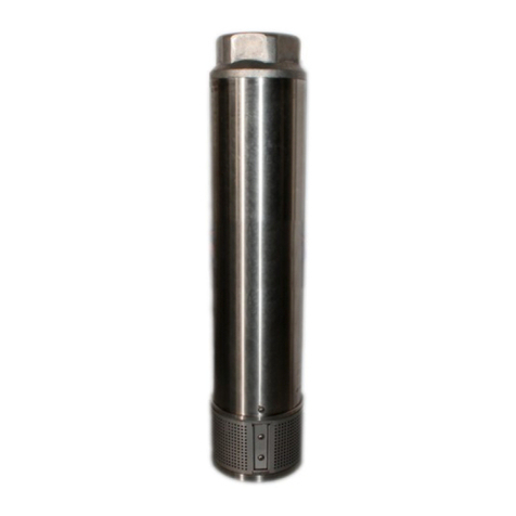
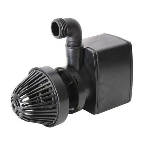
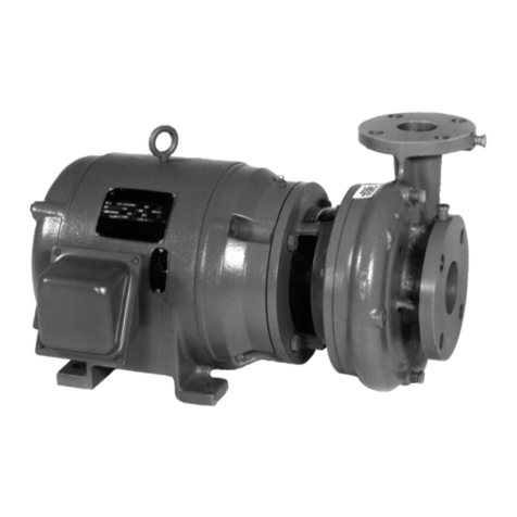
This Submersible Sump Pump is designed to drain flooded
basements, excavations, and construction sites of rain, clear
and dirty water. Operates automatically or manually. 115V, 60
Hz., single phase, permanently split capacitor motor.
Permanently lubricated ball bearings never need lubrication.
Automatic thermal overload protection. Unit is equipped with
a 10’ 3-prong grounding-type power cord.
Housing and base are made of high impact corrosion resis-
tant plastic. Non-clog composite impeller, ceramic shaft
sleeve, and two Buna-N lip seals. Casing, shaft, and external
hardware are stainless steel.
NOTE: This unit is not designed for applications involving salt
water or brine! Use with salt water or brine will void warranty.
Pump water only with this pump.
SPECIFICATIONS
Power supply required ......................................115V, 60 HZ.
Motor duty ..........................................................Continuous*
Liquid Temp. Range...........................32°F to 77°F (0°-25°C)
Circuit Requirement (minimum) ...............................15 Amps
Discharge Adapter:.............................................1-1/4" FNPT
*NOTE: For continuous operation, water depth must be at
least 2" (5 cm).
UNPACKING AND INSPECTION
Handle with care. Check items received against packing list
to be sure that all equipment has been received. Inspect for
shipping damage. If found, file claim with carrier immediately.
INSTALLATION
1. Install pump in sump pit with minimum diameter of 10"
(25,4 cm). Sump depth should be 18" (45,7 cm).
Construct sump pit of tile, concrete, steel, or plastic.
Check local codes for approved materials.
2. Install pump in pit so that switch operating mechanism
has maximum possible clearance.
3. Pump should not be installed on clay, earth, or sand sur-
faces. Clean sump pit of small stones and gravel which
could clog pump. Keep pump inlet screen clear.
NOTE: Do not use ordinary pipe joint compound on plas-
tic pipe. Pipe joint compound can attack plastics.
4. Install discharge plumbing. Use rigid plastic pipe and
wrap threads with Teflon tape or use Plasto Joint Stik1.
Screw pipe into pump hand tight +1 – 1-1/2 turns.
*Lake Chemical Co., Chicago, Illinois
Risk of flooding. If a flexible discharge hose
is used, make sure pump is secured in sump to prevent
movement. Failure to secure pump may allow pump move-
ment, switch interference, and prevent pump from starting or
stopping.
5. To reduce motor noise and vibrations, a short length of
rubber hose (1-7/8" I.D., e.g. radiator hose) can be con-
nected into discharge line near pump using suitable
clamps.
6. Install an in-line check valve (provided with pump) to pre-
vent flow backwards through pump when pump shuts off.
7. Power Supply: Pump is designed for 115 V., 60 Hz.,
operation and requires a minimum 15 amp. circuit. Both
pump and switch are supplied with 3-wire cord sets with
grounding-type plugs. For automatic operation, switch
plug is inserted directly into outlet and pump plug inserts
into opposite end of switch plug. For manual operation,
pump plug is inserted directly into outlet.
Pump should always be electrically
grounded to a suitable electrical ground such as a
grounded water pipe or a properly grounded metallic
raceway, or ground wire system. Do not cut off round
ground pin.
8. If pump discharge line is exposed to outside sub-freezing
atmosphere, portion of line exposed must be installed so
any water remaining in pipe will drain to the outfall by
gravity. Failure to do this can cause water trapped in dis-
charge to freeze which could result in damage to pump.
9. After piping and check valve have been installed, unit is
ready for operation.
10. Check operation by filling sump with water and observing
pump operation through one complete cycle.
Failure to make this operational check
may lead to improper operation, premature failure, and
flooding.
2
GPM (LPM) AT TOTAL FEET (m)
510152025Shut Off
Model HP (1.5m) (3m) (4.6m) (6m) (7.6m)
CAPACITY GALLONS(L)/MINUTE
30.9 24.0 16.9 – – 20
D125110VB 1/4 (117.0) (90.8) (64.0) (–) (–) (75.7)
35.2 28.0 20.8 11.4 – 24
D133110VB 1/3 (133.2) (106.0) (78.7) (43.3) (–) (90.8)
42.0 33.8 25.0 15.5 4.8 27
D150110VB 1/2 (159.0) (128.0) (94.6) (58.6) (18.2) (102.2)
No flow at
height shown
below
PERFORMANCE
Model Motor Minimum Full Circuit Cord Switch Setting in inches (mm)
Number HP Load Amps Required (Amps) Length On Off
D125110VB 1/4 2.5 15 10’ 7-9" (178-229) 1-2" (25-51)
D133110VB 1/3 2.7 15 10’ 7-9" (178-229) 1-2" (25-51)
D150110VB 1/2 3.0 15 10’ 7-9" (178-229) 1-2" (25-51)
MOTOR, SWITCH, & CORD SPECIFICATIONS


