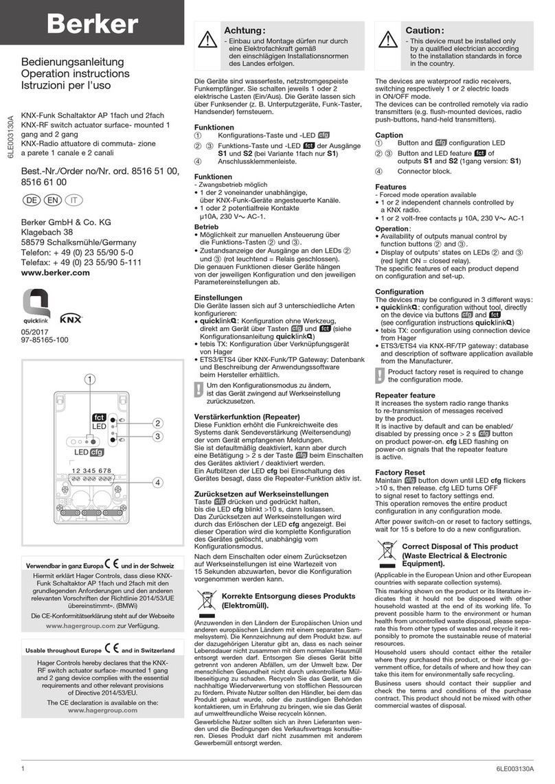
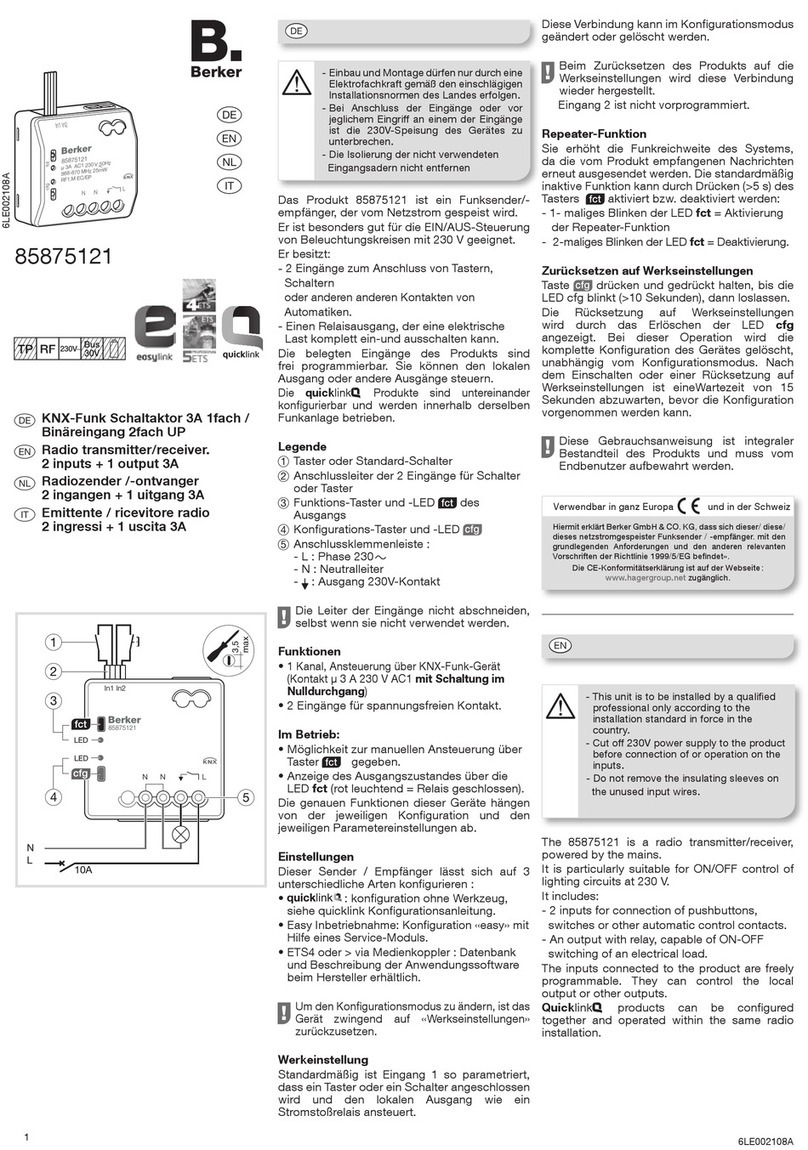
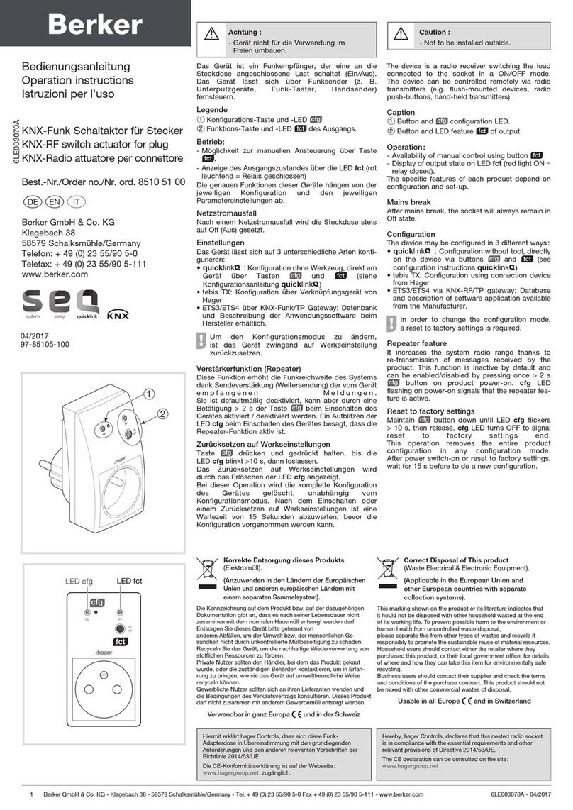
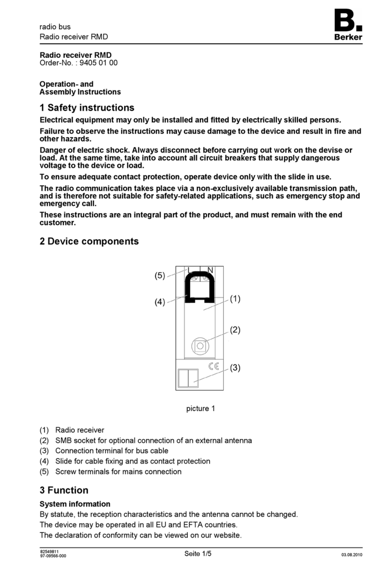
Berker Radio Touch 2880 Series User manual

Radio Touch
Radio Touch
Order no.: 2880 xx
Operation and installation instructions
1 Safety instructions
Electrical equipment must only be installed and assembled by a qualified electrician in
accordance with the relevant installation standards, regulations, directives and safety
and accident prevention directives of the country.
Failure to comply with these instructions may result in damage to the device, fire, or
other hazards.
Disconnect load before working on the device. Take all circuit breakers that feed
dangerous voltages to the device into account.
These operating instructions are an integral component of the product, and must be
retained by the end user.
2 Structure of the device (Figure 1)
(1) Frame 2-gang
(2) Radio Touch cover
(3) Centre plate for loudspeaker
(4) Loudspeaker insert
(5) Radio Touch insert
Scope of delivery: radio and loudspeaker with Design parts and fastening screws.
97-09894-000
Page 1/12 05/2013

Radio Touch
3 Function
The radio receives FM radio stations and outputs them via the connected loudspeaker.
Additional functions:
–Capacitive touch display
–Manual and automatic station search
–8 memory slots
–Display of reception frequency and RDS information
–Display of date and time in Standby mode
–Automatic date and time setting on RDS reception
–Alarm with radio or acoustic signal
–Timer (countdown) with acoustic signal when expired (also during radio reception)
–Sleep mode with automatic switch-off
–Display brightness settable in 10 levels and 8 times
–Extension connection, e.g. for switch, controller
–AUX-IN for external audio sources, e.g. docking station or MP3 player to multimedia socket
outlet
Correct use
–Only suitable for use in indoor areas
–Flush-mounting in wall box according to DIN 49073
–Radio and loudspeaker each mounted in a wall box
4 Operation
Operation solely using touch operating surfaces.
Operating concept (Figure 2)
(6) Switch on/switch off
(7) Jump back to the higher-level operating level
(8) Scroll down/reduce value
(9) Decrease volume
(10) Increase volume
(11) Scroll up/Increase value
(12) Touch display with variable display/operating areas
97-09894-000
Page 2/12 05/2013

Radio Touch
The six symbolic operating elements, arranged at the top and bottom of the display, represent
fixed buttons for frequent operations.
Figure 3
Either a 3- or 5-line menu (Figure 3) or up to 9 fields for the settings (Figure 2) are shown on the
display.
Longer lines of text are shown in a loop after a second’s delay.
Switching on the radio
The radio is in Standby mode, the date and time are displayed.
Touch the display or button (Figure 2, 6).
The radio outputs the most recently set station.
Details such as station type, station name, transmitter frequency, song name, storage
location and reproduction mode are displayed with RDS reception.
Selecting menu items
The radio is switched on.
Touch the button until main menu appears (Figure 3).
Touch the button or the display.
The active display in the central operating panel - shown in bold - changes.
Touch the active display with the desired menu item.
A new menu opens.
If necessary, an additional selection must be made in the menu, before settings are
possible.
Changing settings
The menu item is selected - e.g. Countdown. The first setting is active - e.g. hours hrs.
Use the button to set the desired number.
97-09894-000
Page 3/12 05/2013

Radio Touch
Figure 4
Using the control panel, apply the number of another setting, e.g. min or sec or save the
settings with (Figure 4).
Adjust other settings accordingly.
The order and number of settings is arbitrary.
The active setting is displayed in square brackets.
Setting the volume
The radio is switched on.
Press the button (Figure 2, 10/9).
The sound is played back louder/more quietly.
With control panel , switched to mute during volume setting.
Pressing the volume bar at the bottom in the middle or at the top - when setting the
volume - adjusts the volume to 30%, 60% or 100%.
Setting the date and time manually
The radio is switched on.
Touch the button until main menu appears (Figure 3).
Select the Timer control panel with the buttons and press it.
Select Time/Date with and press it.
Select Manual with and press it.
Using , select the date format EU / US and, using another control panel, apply, e.g.
year.
Using , select the year and apply with month.
Using , select the month and apply with day.
Using , select the day and apply with hrs.
Using , select the hours and apply with min.
Using , select the minutes and press to save all the settings.
97-09894-000
Page 4/12 05/2013

Radio Touch
Setting an FM station with automatic search
The radio is switched on.
button until main menu appears (Figure 3).
Touch the
Select the control panel FM Radio using and press it.
Select the Automatic Scan control panel with and press it.
The first station to be found will be played back and shown in the display.
continues the automatic search without saving.
Saving stations).
Pressing
or:
Save the station (see
Setting an FM station with manual search
The radio is switched on.
button until main menu appears (Figure 3).
Touch the
Select the control panel FM Radio using and press it.
Select the control panel Manual Seek using and press it.
s using
Increase/reduce the reception frequency in 0.1 MHz step until a station is
received without interference.
97-09894-000
Page 5/12 05/2013
Press to continue the manual search without saving.
).
tation is played back.
Press Save.
or:
Save the station (see Saving stations
Saving stations
The searched for s
Press the station display in the control panel.
Select New station using and press it to save.
or:
Select the saved radio station with and press it to overwrite.
Opening a saved station
The radio is switched on.
button until main menu appears (Figure 3).
Touch the
Select the control panel FM Radio using and press it.
Select the saved station using and press it.
If a storage slot is opened, it is possible to skip to the next or previous storage slot using
.
Deleting stations
The station to be deleted is played back.
Press the control panel with the station display.
Delete this storage slot using Delete.

Radio Touch
Setting the alarm
The radio is switched on.
Touch the button until main menu appears (Figure 3).
Select the Timer control panel with the buttons and press it.
Select Wake Up with and press it.
Select On with and press it.
If necessary, switch to 24h/AM/PM display.
Press the time to be set (hours, minutes or seconds). Set the time using (Figure 2).
Press and, using , select and press a radio station or the electronic alarm signal.
Press to apply the settings.
When the alarm is active and the radio switched off, the alarm symbol is displayed.
Alarm operations can be terminated using or moved by intervals of 5 minutes (snooze)
by pressing another control panel.
Setting a countdown
The radio is switched on.
Touch the button until main menu appears (Figure 3).
Select the Timer control panel with the buttons and press it.
Select Countdown with and press it.
Press the time to be set (hours, minutes or seconds). Using , set the time shown in
brackets (Figure 4).
If necessary, set additional times.
Apply the time setting using and activate the countdown.
After the time has elapsed, an acoustic signal will sound - even if radio is being received.
The Sleep Mode function can be set accordingly.
Setting the language
Touch the button until main menu appears (Figure 3).
Select the Setup using the buttons and press it.
Select the Language using and press it.
Select the appropriate language with and press it.
The Backlight, Reset of Defaults and Sound functions can be set in the same way.
Setting to external audio device
Touch the button until main menu appears (Figure 3).
Select the AUX In control panel using the buttons and press it.
97-09894-000
Page 6/12 05/2013

Radio Touch
5 Information for electricians
5.1Installation and electrical connection
DANGER!
Touching live parts can result in an electric shock.
An electric shock can lead to death.
Before working on the device or load, disconnect all associated circuit breakers.
Cover all live parts in the area!
Connections on the radio insert (Figures 5 and 6) for:
(13) Loudspeaker (L, R)
(14) External audio devices AUX IN
(15) Antenna
(16) Radio application module (12-pole jack)
97-09894-000
Page 7/12 05/2013

Radio Touch
(17) 230 V~ lead
(18) Extension unit
Connecting radio to lead
The lead is protected by means of a circuit breaker (max 16 A).
Connect the 230 V~ lead to the Land N terminals (Figure 6, 17).
If necessary, connect the extension unit (Figure 6, 18).
Do not connect the load cable directly to the extension unit terminal but connect it directly
to the switch or in connection boxes.
When switching on energy-saving lamps, electronic transformers and ballasts on the
extension unit input, interference pulses may occur. We recommend wiring the extension
unit input with a separate contact e.g. with a 2-pole switch or additional relay.
Connecting loudspeakers and auxiliary devices
DANGER!
If the loudspeakers are connected to the operating voltage in a shared cable, the
operating voltage can reach the loudspeaker cables. Electric shock possible
through touching the loudspeaker cable.
An electric shock can lead to death.
Route a separate loudspeaker wire.
At least one loudspeaker must be connected for radio operation.
Connect loudspeakers to the terminals (red) and (white) (Figure 5, 13).
97-09894-000
Page 8/12 05/2013

Radio Touch
Figure 7
Figure 8
Figure 9
97-09894-000
Page 9/12 05/2013

Radio Touch
If necessary, connect other external devices (Figures 7, 8 or 9).
In stereo mode with two loudspeakers, the control panel with the station display can be
used to switch manually to mono operation.
Only use wires that are adjusted for the mains voltage method of laying.
Wires must be mounted in such a way, e.g. with cable ties, that a detached wire will not
touch another potential in the event of a fault.
Use shielded wires for interference-free signal transmission. Connect the shield to the
terminal according to the terminal labelling.
In combinations or in the immediate vicinity of electronic devices (e.g. ballasts), radio
reception can be disturbed. Before installation at the assembly location, put the radio into
operation and test it for interference. In case of interference, increase the distance to the
source of interference.
When using an antenna wire as an external antenna, make sure that the wire and the tip of
the antenna are insulated against 230 V.
Assembling the device (Figure 1)
The inserts are connected.
Insert the inserts (Figures 1, 4 and 5) correctly into the wall boxes and fasten them with the
screws provided.
Place the 2-gang frame (Figure 1, 1) over the inserts and attach the Radio Touch
application module (Figure 1, 2) and the loudspeaker centre plate (Figure 1, 3).
Carefully guide the contact pins on the radio application module into the socket
(Figure 5, 16) on the insert without bending them.
Assemble the Radio Touch and loudspeaker separately with two 1-gang frames or in
combinations.
5.2Radio start-up
The radio is assembled.
Switch the operating voltage on.
The display shows Enter Time/Date! and back.
Press the Enter Time/Date! control panel.
The control panels Automatic, Manual and Time Zone appear.
Press Automatic.
The time and date are set automatically as soon as a station with RDS reception is saved
(see setting FM station with automatic search).
If no RDS signal is received, Manual must be selected (see Setting time and date
manually).
When using 2 loudspeakers, both loudspeakers should be activated under Setup, Sound.
When using an antenna, the external antenna must be activated under Setup,
FM Antenna.
97-09894-000
Page 10/12 05/2013

Radio Touch
6 Appendix
The device is at the end of its serviceable life never throw it away in the household
waste under any circumstances. The local authorities provide information about
environmentally-friendly disposal.
When used as intended, this device complies with the requirements of the R&TTE
Directive (1999/5/EC). A complete declaration of conformity can be found on the
Internet at www.berker.com.
6.1Technical Data
Radio Touch
Operating voltage 230 V~, 50/60 Hz
Rated current 0.2 A
Power consumption at rated output power 7 W
Stand-by operation 1.3 W
Music rated power output (sine) per channel 1.5 W
Loudspeaker impedance 4 ... 8 Ω/channel
Input impedance AUX IN 10 kΩ
Frequency range FM 87.5 ... 108 MHz
Operating temperature 5 ... 40 °C
Protection class II
Protection type IP20
Connecting terminal Screw terminals
Mains connection 2.5 mm²
Loudspeaker/AUX 1 mm²
Cable lengths:
Loudspeaker max. 20 m
AUX IN max. 3 m
Extension units max. 50 m
Installation depth 33 mm
Loudspeaker
Loudspeaker impedance 8 Ω
Sine output/music output 4/8 W
Frequency range 170 Hz ... 20 kHz
Prefabricated cable length approx. 30 cm
6.2Accessories
Loudspeaker 2882 xx xx
Docking station 2883 xx xx
USB/3.5 mm Audio socket outlet 33 1539 xx xx
3 x Cinch/S-video socket outlet 33 1532 xx xx
Switches, controllers and timers are suitable as extension units. The same phase should
be used as for the radio.
6.3Troubleshooting
Poor FM radio reception
Cause 1: Internal FM antenna insufficient for reception.
Connection an additional antenna (Figure 5, 15).
Cause 2: Stereo playback is selected.
Switch to Mono.
97-09894-000
Page 11/12 05/2013

Radio Touch
Poor audio signal during operation in an external audio device
Cause 1: An insufficiently shielded cable was used for the connection.
Replace the connecting cable for the external audio device.
Cause 2: Shield of the cable is not connected correctly to the terminal of the AUX IN
connection.
Check the connection of the shield and rectify if necessary.
6.4Warranty
We reserve the right to make technical and formal changes to the product in the interest of
technical progress.
Our products are under guarantee within the scope of the statutory regulations.
If you have a warranty claim, please contact the point of sale or ship the device postage free
with a description of the appropriate regional representative.
Berker GmbH & Co. KG
Klagebach 38
58579 Schalksmühle/Germany
Phone: + 49 (0) 23 55/90 5-0
Fax: + 49 (0) 23 55/90 5-111
www.berker.com
97-09894-000
Page 12/12 05/2013
This manual suits for next models
3
Table of contents
Other Berker Receiver manuals
