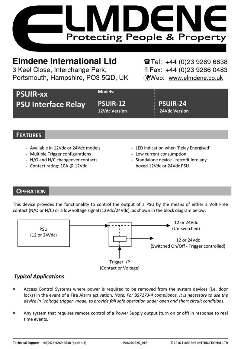
Berker RolloTec 2975 User manual

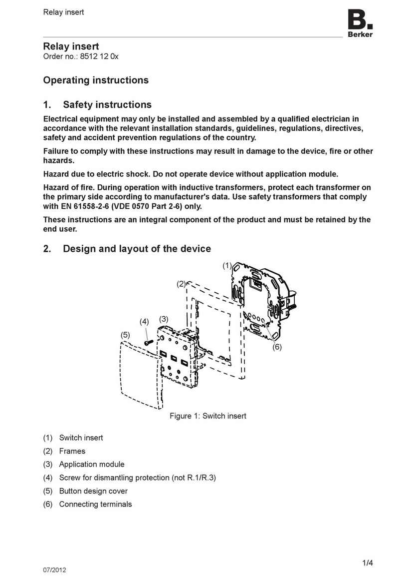
RolloTec®Einsatz
RolloTec®Insert
Inzetregelmoduul
Insert
Best.Nr. 2975
825 166 01 01.2003
Bedienungsanleitung
Operating Instructions
Bedieningshandleiding
Mode d’emploi
RolloTec®

Inhaltsverzeichnis
3
Inhaltsverzeichnis
1. Funktion.............................................................................................................. 4
RolloTec®Einsatz mit RolloTec®Taste ........................................................... 5
RolloTec®Einsatz mit RolloTec®Funk-Taste.................................................. 6
RolloTec®Einsatz mit RolloTec®Speicher-Taste ........................................... 7
RolloTec®Einsatz mit RolloTec®Aufsatzmodul Schaltuhr.............................. 7
2. Gefahrenhinweise .............................................................................................. 8
3. Installationshinweise .......................................................................................... 9
4. Anschluss ........................................................................................................... 12
RolloTec®Einsatz .......................................................................................... 12
RolloTec®Einsatz mit mechanischer Nebenstelle .......................................... 12
RolloTec®Einsatz mit Funk-fernbedienbarer Nebenstelle .............................. 13
RolloTec®Einsatz mit 'Zentralsteuerung' ........................................................ 13
RolloTec®Einsatz mit 'Zentralsteuerung' auf 2 Phasen .................................. 15
RolloTec®Einsatz mit Windalarm .................................................................... 16
RolloTec®Einsatz mit separaten FI-Schaltern ................................................ 18
5. Technische Daten............................................................................................... 19
6. Herstellergarantie ............................................................................................... 20

Funktion
5
Der RolloTec®Einsatz verfügt über 6 Anschlussklemmen und einen Steckverbinder
zur Kontaktierung des Aufsatzes.Zusätzlich kann im Einsatz eine
3-polige Klemme (liegt dem Aufsatz mit Sensoranschluss bei) positioniert werden.
AndieserKlemmewirdbeiUnterputzverlegung undVerwendungeinesAufsatzesmit
SensoranschlussderSonnenschutz-/Dämmerungssensor(Dämmerungsfunktion nur
inVerbindung mit Schaltuhr mit Sensoranschluss) und/oder Glasbruchsensor
angeschlossen.
RolloTec®Einsatz mit RolloTec®Taste
In dieser Kombination wird der RolloTec®Einsatz als manuellerTaster betrieben
(sieheBedienungsanleitung‘Taste’).
Zusätzlich können folgende Funktionen realisiert werden:
- Anschluss von Nebenstellen
-Windalarm
BeiVerwendung des Aufsatzes mit Sensoranschluss:
-Glasbruch-Alarm
-Sonnenschutzfunktion
Funktion
4
1. Funktion
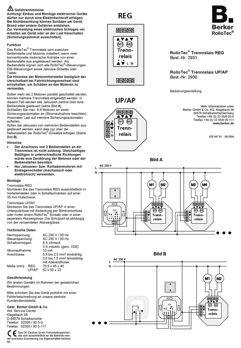
Der RolloTec®Einsatz ist eine Komponente des RolloTec®Systemes und wird in
Verbindung mit
einem RolloTec®Aufsatzmodul Schaltuhr
oder einer RolloTec®Taste
in einer Gerätedose nach DIN 49073 (Empfehlung:tiefe Dose) montiert.
Es ergibt sich somit die Möglichkeit, durch Austausch des Aufsatzes, eine manuelle
Bedienung, eine Komfortbedienung über Fernbedienung oder eine vollautomatische
Zeitsteuerungzurealisieren.
Der RolloTec®Einsatz verfügt über 2 leistungsstarke Relaiskontakte, die
gegeneinander verriegelt sind.Dadurch ist eine gleichzeitige Bestromung des
Jalousiemotors in beide Laufrichtungen und damit eine Beschädigung
ausgeschlossen (siehe Bild).
Durch die elektronischeVerriegelung des Aufsatzes wird eine minimale
Umschaltzeit bei Dauerlauf von 1 Sekunde realisiert.
Über Nebenstelleneingänge können mechanischeTaster und weitere RolloTec®
Einsätze angeschlossenwerden.
Der Nebenstelleneingang 2 (▲) ist auch zur Realisation einer‘Windalarm-Funktion’
verwendbar.
Je RolloTec®Einsatz kann 1 Motor mit Endlagenschalter bis max.1000W
angesteuert werden. Hinweise der Motorhersteller beachten.
L
NL2
Motor
1
Datum
Uhrzeit
Mode Set
Prog Zufall Astro
WS
Mo
Di
Mi
Do
Fr
Sa
So
A
B
C
Datum
Uhrzeit
Mode Set
Prog Zufall Astro
WS
Mo
Di
Mi
Do
Fr
Sa
So
A
B
C
1NL2
Motor
1NL2
Schnittstelle Aufsatz Sensoranschluss
Phase
Nebenstelle Ab Motor Auf
Nebenstelle Auf Motor Ab
Neutralleiter

1NL2
Motor
Datum
Uhrzeit
Mode Set
Prog Zufall Astro
WS
Mo
Di
Mi
Do
Fr
Sa
So
A
B
C
7
RolloTec®Einsatz mit RolloTec®Speicher-Taste
In dieser Kombination wird der RolloTec®Einsatz als automatische Steuerung
mitzweigespeicherten Jalousiefahrzeitenbetrieben.
Das Gerät stellt sich, durch die individuelle Speichermöglichkeit einer Auf- und einer
Abzeit, auf die Gewohnheiten des Anwenders ein.Die beiden gespeicherten Jalousie-
fahrzeitenwerden im24-Stunden-Rhythmuswiederholt.Hierdurchergibt sicheinekom-
fortable,automatische Jalousiesteuerung, diez.B.zurAnwesenheitssimulation genutzt
werdenkann.(sieheBedienungsanleitung’Speicher-Taste’)
Zusätzlich können folgende Funktionen realisiert werden:
- Anschluss von Nebenstellen
-Windalarm
-Glasbruch-Alarm
-Sonnenschutzfunktion
RolloTec®Einsatz mit RolloTec®Aufsatzmodul Schaltuhr
In dieser Kombination wird der RolloTec®Einsatz alsautomatische Steuerung mit
programmierbarenSchaltzeitenbetrieben (siehe Bedienungsanleitung‘Schaltuhr‘).
Zusätzlich können folgende Funktionen realisiert werden:
- Anschluss von Nebenstellen
-Windalarm
BeiVerwendung des Aufsatzes mit Sensoranschluss:
-Glasbruch-Alarm
-Sonnenschutzfunktion
-Dämmerungsfunktion
Funktion
RolloTec®Einsatz mit RolloTec®Funk-Taste
In dieser Kombination wird der RolloTec®Einsatz als funkfernbedienbarer Taster
betrieben.
Die Funk-Taste muss auf den gewünschten Senderkanal gelernt werden (siehe
Bedienungsanleitung‘Funk-Taste’).
Zusätzlich können folgende Funktionen realisiert werden:
- Anschluss von Nebenstellen
-Windalarm
-Glasbruch-Alarm
-Sonnenschutzfunktion
Funktion
6
1NL2
Motor
1NL2
Motor

9
Installationshinweise
3. Installationshinweise
Wichtig:Die Sensorleitung führt Schutzkleinspannung (SELV).Installations-
vorschriften nachVDE 0100 beachten.
Anschluss Sensor:
UP-Verlegung (Bild A):
Zur UP-Verlegung der Sensorleitung geeignete Leitung wählen.
Empfehlung:Telefonleitung J-Y(ST)Y 2x2x0,6 mm².Die Einzeladern der
Sensorleitung werden durch einen Isolierschlauch (liegt den Aufsätzen mit
Sensoranschluss bei) geführt.Die Leitung wird dann, zusammen mit dem
Isolierschlauch, durch die Bohrung des Einsatzes gesteckt und durch den
Leitungskanal zur Anschlussklemme geleitet.Der Isolierschlauch muss die
Einzeladern von der äusseren Leitungsisolierung bis zur Anschlussklemme
umschliessen.Die Anschlussklemme (liegt den Aufsätzen mit Sensoranschluss bei)
wird, entsprechend der Abbildung, in den Einsatz eingelegt.
AP-Verlegung (Taste mit Sensoranschluss) (Bild B):
Die Sensorleitung wird hinter der Tragplatte (zwischenWand undTragplatte)
durch die Öffnung in den Leitungskanal des Einsatzes eingeleitet.Die Leitung
wird direkt durch den Leitungskanal zur Anschlussklemme geführt.Die Leitung
muss präzise im Leitungskanal liegen und darf keine Schlaufen zum 230V
Anschlussklemmraumbilden.
8
Gefahrenhinweise
2. Gefahrenhinweise
Achtung! Einbau und Montage elektrischer Geräte dürfen nur durch eine
Elektrofachkraft erfolgen.
Werden unterschiedliche Phasen verwendet,muss im Fehlerfall oder bei
Arbeiten an der Installation allpolig abgeschaltet werden.
Steuerleitungen nicht parallelzuMotorleitungen legen (Einkopplungsgefahr).
RolloTec®wurde zum Schalten von Jalousie- bzw.Rolladenmotoren entwickelt.
Keine anderen Lasten schalten.
Sollen Jalousiemotoren parallel geschaltet werden, unbedingt Angaben der
Motorenhersteller beachten.Andernfalls könnten die Motoren zerstört werden.
Nur Jalousien bzw.Rolladen mit Endlagenschalter (mechanisch oder elektronisch)
verwenden.Angaben der Motorhersteller beachten.
Hinweise der Motorenhersteller bezüglich Umschaltzeit und max.Einschaltdauer
(ED)beachten.
RolloTec®wurde für das automatische Betätigen von Fenster-Jalousien entwickelt.
Andere Anwendungen können Gefahren mit sich bringen, z.B.die Steuerung eines
Rolltores.
Diese Gefahren müssen vom Anwender durch Einsatz zusätzlicher geeigneter
Sicherheitsmassnahmen(z.B.Lichtschranken)ausgeschlossenwerden.
A
B

11
Installationshinweise
Der RolloTec®Einsatz kann nur in Verbindung mit einem der folgenden Aufsätzen in
Betrieb genommen werden:
RolloTec®Taste
RolloTec®Funk-Taste
RolloTec®Speicher-Taste
RolloTec®Aufsatzmodul Schaltuhr Easy
RolloTec®Aufsatzmodul Schaltuhr
Der RolloTec®Einsatz wird in einer Gerätedose nach DIN 49073 (Empfehlung:
tiefe Dose) montiert.
Die Anschlussklemmen des Einsatzes müssen dabei unten liegen.
Der Aufsatz wird zusammen mit dem Rahmen auf den Einsatz aufgesteckt.
Die elektrische Kontaktierung erfolgt über den Stecker.
Die zusätzlichen Steckkontakte beim Aufsatz mit Sensoranschluss werden, zum
Anschluss einer Sensorleitung, in den Einsatz geführt. Der Anschluss des Sensors
erfolgtüber Schraubklemmen.
Installationshinweise
10
AP-Verlegung (Schaltuhr mit Sensoranschluss) (Bild C):
DerAnschlussdesSensorsbzw.desAdapterserfolgtübereinenSteckeramAufsatz.
Anschluss an Klemmblock im Einsatz:
Sensorleitungen nach nebenstehendem Schema (Bild) anschliessen.
KennzeichnungderLeitungsadern:
Sensoren: ‘Masse’=gekennzeichnet.
Adapter,Verlängerungsleitung: ‘Sonne’=gekennzeichnet
‘Masse’=mittlere Leitung
Sollen Sonnen-/ Dämmerungssensor und Glasbruchsensor gleichzeitig betrieben
werden, Adapter verwenden (nicht im Lieferumfang enthalten).Der Adapter wird am
Aufsatz mit Sensoranschluss oder am Einsatz über die 3polige Anschlussklemme
angeschlossen.DerAdapterverfügtüber 2BuchsenzumAnschluss derSensorstecker.
Sonn
e
Glas Masse
C

Anschluss
13
Anschluss RolloTec®Einsatz mit Funk-fernbedienbarer Nebenstelle.
Hinweis: Solange ein Auf-Befehl am Nebenstelleneingang ‘2’anliegt, kann die
Jalousie am Gerät selbst nicht manuell oder automatisch bedient werden.
Anschluss RolloTec®Einsatz mit ‘Zentralsteuerung’.
Beispiel A für 2 Jalousiemotoren:
Einsatz mit Schaltuhr.Einsatz und mit IR-Taste oderTaste.
Die automatische und manuelle Steuerung beider Motoren erfolgt‘zentral’über
Einsatz mit Schaltuhr.Die Schaltbefehle werden für beide Motoren
gleichermaßen ausgewertet. Es wird ein gemeinsames Auf- oder Abfahren der
angeschlossenen Motoren ermöglicht (z.B.Morgens zentraler Auf-Befehl und
Abends zentraler Ab-Befehl für alle angeschlossenen Jalousiemotoren).
Der Motor M1 (Einsatz ) und M2 (Einsatz ) ist zusätzlich manuell über IR-Taste
oderTastebedienbar.
Es können entsprechend dem Schaltbild weitere Einsätze hinzugefügt werden.
Anschlusswerte der Leitungsschutzschalter beachten.
Hinweis: Solange ein Auf-Befehl am Nebenstelleneingang ‘2’anliegt, kann die
Jalousie am Gerät selbst nicht manuell oder automatisch bedient werden.
Anschluss
12
4. Anschluss
Empfehlung:ZurVerschaltung zweier Einsätze, zwischen den Einsätzen Leitung
5x1,5 mm² verwenden (1, 2, L, N, PE).
Anschluss RolloTec®Einsatz.
Anschluss RolloTec®Einsatz mit mechanischer Nebenstelle (Jalousie-Taster
mit mechanischerVerriegelung).
BeiVerwendung von Jalousie-Tastern geht der RolloTec®Einsatz nicht in
Selbsthaltung (Dauerlauf). Die Jalousie muss durch manuellesTasten in die
gewünschte Position gefahren werden.
Ist das nicht erwünscht, Jalousie-Schalter mit mechanischer Verriegelung einsetzen.
Hinweis: Solange ein Auf-Befehl am Nebenstelleneingang‘2’anliegt, kann die
Jalousie am Gerät selbst nicht manuell oder automatisch bedient werden.

Anschluss
15
Anschluss RolloTec®Einsatz mit‘Zentralsteuerung’auf 2 Phasen.
Der Anschluss auf mehreren Phasen bietet die Möglichkeit, die Zentralsteuerung
auf einer anderen Etage oder in einem anderen Raum zu installieren.
Beispiel für 2 Jalousiemotoren:
Einsatz , und mit Funk-Taste oder Taste.Einsatz mit Schaltuhr.
Der Motor M1 (Einsatz ) und M2 (Einsatz ) wird manuell über Funk-Taste oder
Taste bedient.Beide Motoren werden gleichzeitig über Einsatz angesteuert.
Die automatische und manuelle Steuerung beider Motoren erfolgt zusätzlich
‘zentral’über Einsatz mit Schaltuhr.Die Schaltbefehle werden für beide Motoren
gleichermassen ausgewertet.Es wird ein zeitgleiches Auf- oder Abfahren der
angeschlossenen Motoren ermöglicht (z.B.Morgens zentraler Auf-Befehl und
Abends zentraler Ab-Befehl für alle angeschlossenen Jalousiemotoren).
Es können entsprechend dem Schaltbild weitere Einsätze hinzugefügt werden.
Anschlusswerte der Leitungsschutzschalter beachten.
Hinweis: Solange ein Auf-Befehl am Nebenstelleneingang ‘2’anliegt, kann die
Jalousie am Gerät selbst nicht manuell oder automatisch bedient werden.
Anschluss
14
Anschluss RolloTec®Einsatz mit‘Zentralsteuerung’.
Beispiel B für 2 Jalousiemotoren:
Einsatz , und mit Schaltuhr.
Die automatische und manuelle Steuerung von Motor M1 und M2 erfolgt nach
individueller Programmierung der Schaltuhr und (z.B.Sonnenschutzfunktion).
Über Einsatz mit Schaltuhr erfolgt die‘zentrale’Steuerung.Schaltbefehle
entsprechend der Programmierung von Aufsatz werden für beide Motoren
ausgeführt (z.B.Abends zentraler Ab-Befehl für alle angeschlossenen
Jalousiemotoren).
Es können entsprechend dem Schaltbild weitere Einsätze hinzugefügt werden.
Anschlusswerte der Leitungsschutzschalter beachten.
Hinweis: Solange ein Auf-Befehl am Nebenstelleneingang‘2’anliegt, kann die
Jalousie am Gerät selbst nicht manuell oder automatisch bedient werden.

Anschluss
17
Anschluss RolloTec®mitWindalarm (Zentralsteuerung mit 2 Gruppen)
Bei Windalarm wird die Jalousie aufgefahren und bleibt dort verriegelt, bis der Wind
abnimmt.
Diese Verriegelung hält solange an, wie ein Auf-Befehl am Nebenstelleneingang‘2’
anliegt.
Daher kann die Jalousie nicht manuell oder automatisch bedient werden.
Hinweise:
Glasbruchsensoren dürfen nicht zusammen mit demWindsensor verwendet
werden.DieWindschutzfunktion (Jalousie fährt auf) ist nach Glasbruch
gesperrt,die Jalousie oder Rollade bleibt geschlossen.
Anschluss
16
Anschluss RolloTec®mitWindalarm
Bei Windalarm wird die Jalousie aufgefahren und bleibt dort verriegelt, bis der Wind
abnimmt.
Diese Verriegelung hält solange an, wie ein Auf-Befehl am Nebenstelleneingang‘2’
anliegt.
Daher kann die Jalousie nicht manuell oder automatisch bedient werden.
Hinweise:
Glasbruchsensoren dürfen nicht zusammen mit demWindsensor verwendet
werden.DieWindschutzfunktion (Jalousie fährt auf) ist nach Glasbruch
gesperrt, die Jalousie oder Rollade bleibt geschlossen.

Technische Daten
19
5.Technische Daten
Nennspannung :AC 230 V, 50 Hz, N-Leiter erforderlich
Schaltleistung :max. 1 Motor 1000W
Relaisausgang :2 potentialbehaftete Schliesser
(gegeneinanderverriegelt)
Impulsdauer
RolloTec®Taste :2 Minuten
RolloTec®Speicher-Taste :2 Minuten
RolloTec®Funk-Taste :2 Minuten
RolloTec®AufsatzmodulSchaltuhr :Standardwert 2 Minuten,
gelernt 1 Sekunde - 12 Minuten
Umschaltzeit bei Dauerlauf :min. 1 Sekunde
(elektronischeVerriegelung durch Aufsatz)
Anschlussklemmen :Schraubklemmen
für max. 2,5 mm² oder 2 x 1,5 mm²
1, 2, N, , , L
Leitungsschutzschalter :max. 16 A
Anschluss
18
Anschluss RolloTec®in Installationen mit separaten Fehlerstrom-
Schutzschaltern (FI)
Um unerwünschtes Auslösen der FI-Schalter zu vermeiden, müssen die beiden
‘Stromkreise’galvanisch entkoppelt werden.
BitteTrennrelaisverwenden.

Berker GmbH & Co. KG
Abt.Service Center
Klagebach 38
D-58579Schalksmühle
Telefon: 0 23 55 / 90 5-0
Telefax: 0 23 55 / 90 5-111
21
GB
Contents
Contents
1. Function ............................................................................................................. 22
RolloTec®insert with RolloTec®push-button.................................................... 23
RolloTec®insert with RolloTec®radio push-button ........................................... 24
RolloTec®insert with RolloTec®memory push-button ...................................... 24
RolloTec®insert with RolloTec®clock timer attachment ................................... 25
2. Warning ............................................................................................................. 26
3. InstallationInstructions ...................................................................................... 27
4. Connection......................................................................................................... 30
RolloTec®insert ................................................................................................ 30
RolloTec®insert with mechanical extension ..................................................... 30
RolloTec®insert with radio control push button................................................. 31
RolloTec®insert with 'Central Control' .............................................................. 31
RolloTec®insert with 2-phase‘central control’ .................................................. 33
RolloTec®insert with wind alarm function ......................................................... 34
RolloTec®insert in systems with separate residual-current
circuit breakers (FI) .......................................................................................... 36
5. Specifications...................................................................................................... 37
6. Manufacturer'sWarrenty ..................................................................................... 38
Herstellergarantie
20
6. Gewährleistung
Wir leisten Gewähr im Rahmen der gesetzlichen Bestimmungen.
Bitte schicken Sie das Gerät portofrei mit einer Fehlerbeschreibung an unsere
zentrale Kundendienststelle:

23
Function
The RolloTec®insert has six connection terminals and one connector for
contactingtheattachment.
In addition, a three-pole terminal (added to the attachment with sensor connection)
can be positioned in the insert. For flush-mounted installation and use of an
attachment with sensor connection, the sun protection/ twilight sensor (twilight
sensor only in conjunction with the timer) and/or the glass breakage sensor is
connected to this terminal.
RolloTec®insert with RolloTec®push-button
In this combination, the RolloTec®insert is operated as a manual push-button
(please refer to the‘Push-Button’Operating Instructions).
In addition, the following functions can be implemented:
- Connection of extensions.
-Wind alarm.
When the attachment with sensor connection is used:
- Glass breakage alarm.
- Sun protection function.
22
Function
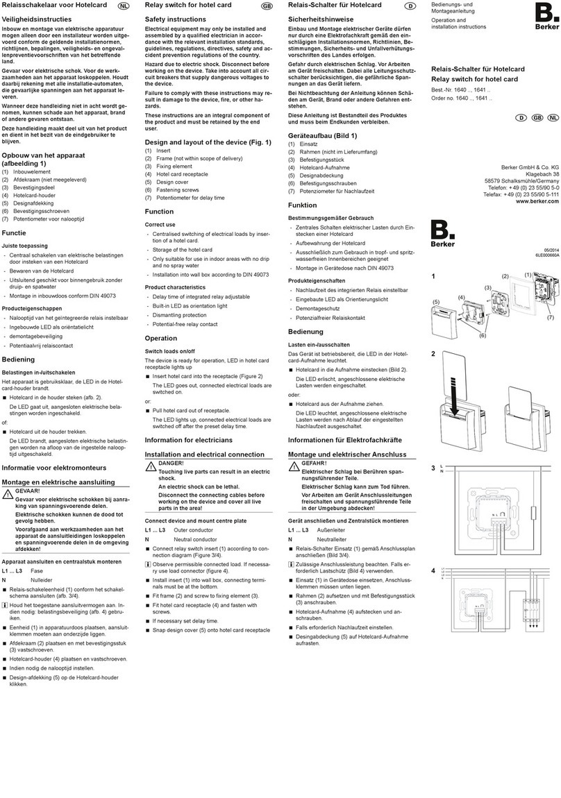
1. Function
The RolloTec®insert is a component of the RolloTec®system and is installed in a
box as per DIN 49073 (recommendation:deep box) in conjunction with
a RolloTec®clock timer attachment module
or a RolloTec®pushbutton.
Thus, it is possible to implement manual control, comfort remote control, or fully
automatic time control by just changing the attachment.
The RolloTec®insert has two efficient relay contacts locked against each other.
This makes impossible powering the louver motor into both directions, thus avoiding
damage to it (please refer to the illustration).
An electronic locking of the attachment provides for a minimum change-over time of
1 second for continuous operation.
Via extension inputs, mechanical push-buttons and further RolloTec®inserts can
be connected.Extension input 2 (▲) can also be used for implementing a‘wind
alarm function’.
One motor provided with a limit switch and up to 1000W max. can be actuated
per RolloTec®insert. Please observe the information given by the motor
manufacturers.
1NL2
Motor
1NL2
Attachment interface Sensor connection
Phase
Extension down Motor up
Extension up Motor down
Neutral
L
NL2
Motor
1
Datum
Uhrzeit
Mode Set
Prog Zufall Astro
WS
Mo
Di
Mi
Do
Fr
Sa
So
A
B
C
Datum
Uhrzeit
Mode Set
Prog Zufall Astro
WS
Mo
Di
Mi
Do
Fr
Sa
So
A
B
C

25
Function
RolloTec®insert with RolloTec®clock timer attachment
In this combination, the RolloTec®insert can be operated as an automatic control
system with programmable switching time events (please refer to the‘Timer’
OperatingInstructions).
In addition, the following functions can be implemented:
- Connection of extensions.
-Wind alarm.
When the attachment with sensor connection is used:
- Glass breakage alarm.
- Sun protection function.
-Twilight function.
24
Function
RolloTec®insert with RolloTec®radio push-button
In this combination, the RolloTec®insert is used as a radio-controlled push-button.
The radio push-button must be taught in to the desired transmitter channel
(refer to the‘Radio push-button’Operating Instructions).
In addition, the following functions can be implemented:
- Connection of extensions.
-Wind alarm.
- Glass breakage alarm.
- Sun protection.
RolloTec®insert with RolloTec®memory push-button
In this combination, the RolloTec®insert is used as automatic control with two
stored louver moving times.
Due to the possibility of individually storing one up and one down time, the unit adapts to
the practise of the user.The two stored louver moving times are repeated at a 24 hour
cycle.This provides comfortable, automatic louver control which can, for example, be
usedforpresence simulation.(Refertothe'Memory Push-Button'OperatingInstructions.)
In addition, the following functions can be implemented:
- Connection of extensions.
-Wind alarm.
- Glass breakage alarm.
- Sun protection function.
1NL2
Motor
1NL2
Motor
Datum
Uhrzeit
Mode Set
Prog Zufall Astro
WS
Mo
Di
Mi
Do
Fr
Sa
So
A
B
C
1NL2
Motor

Installation Instructions
27
3. Installation Instructions
Important:The sensor wiring carries protective low voltage (SELV).Please
observe the installation procedures as specified byVDE 0100.
Connecting the Sensor:
Buried Installation (Fig. A):
Choose wiring suitable for buried installation.
Recommendation:J-Y(ST)Y 2x2x0.6 mm² telephone cable.The individual wires of
the sensor wiring should be run through insulating tubing (comes with the inserts
with sensor evaluation).Then, thread the wiring through hole of the insert
together with the insulating tubing and lead it to connecting terminal through line
duct .The insulating tubing must cover the individual wires from the outer cable
insulation to the connecting terminal. Place the connecting terminal (comes with the
inserts with sensor evaluation) into the insert as shown in the illustration.
Surface Installation (Push-Button with Sensor Evaluation) (Fig.B):
Thread sensor wiring through opening behind the supporting plate (between
the wall and the supporting plate) into line duct of the insert.The wiring should be
routed directly through the line duct to connecting terminal .The wiring must be
precisely located in the line duct and must not form any loops towards the 230V
connectingterminal chamber.
Warning
2.Warning
Attention:Electrical equipment must be installed and fitted by qualified
electricians only.
If different phases are used all poles will have to be disconnected in case of
malfunctioning or when work is done on the installation.
Do not lay control wiring in parallel with motor connection wiring (hazard of coupling).
The RolloTec®system has been designed for switching louver or roller blind motors.
Do not switch any other loads.
If louver motors are to be connected in parallel it will be mandatory to observe the
information given by the motor manufacturers.Otherwise, the motors might get
damaged.
Use louvers or roller blinds with limit switches (mechanical or electronic) only.
Please observe the information of the motor manufacturers.
Please observe the information of the motor manufacturers with respect to change-
over time and max.cyclic duration factor.
The RolloTec®system has been designed for the automatic actuation of window
louvers.Other applications such as controlling a rolling door may entail danger.
Such danger must be made impossible by the user by employing additional suitable
safety measures (e.g. light barriers).
26
A
B
A
B

29
Installation Instructions
The RolloTec®insert can only be set into operation in conjunction with one of the
followingattachments:
RolloTec®pushbutton
RolloTec®radio control pushbutton
RolloTec®memory pushbutton
RolloTec®clock timer attachment module Easy
RolloTec®clock timer attachment module
Install the RolloTec®insert in a connecting box according to DIN 49073
(recommendation:deep box).
The connection terminals of the insert must be in downward position.
Plug attachment onto the insert, together with frame .
Electrical contacting is established through plug .
For the attachment with sensor evaluation, additional plug-in contacts must be led
into the insert to connect a sensor line.The sensor must be connected by screw
terminals.
Installation Instructions
28
C
Sun
G
lass Earth
Surface installation (RolloTec®timer with sensor evaluation) (Illustration C):
The sensor or adapter must be connected to the attachment by a plug.
Connect to the terminal block in the insert:
Connect sensor lines as shown in the opposite diagram (illustration).
Markings of the line wires:
Sensors : ‘Earth’= marked.
Adapter, extension line : ‘Sun’= marked.
‘Earth’= middle wire.
If a sun/twilight sensor and a glass breakage sensor are to be run at the same time,
use an adapter (not within the scope of supplies). Connect the adapter to the
attachment with sensor evaluation or to the insert via the three-pole terminal.The
adapter has two jacks for the connection of the sensor plugs.

31
Connection
Connection of RolloTec®insert with IR remote control extension.
Important: As long as an UP command is applied to extension input‘2’the louver
cannot be actuated manually or automatically on the unit itself.
Connection of RolloTec®insert with‘central control’.
Example A for 2 louver motors:
Insert withRolloTec®timer.Inserts and withRolloTec®radiocontrolpushbutton
or RolloTec®pushbutton.
The automatic and manual control of both motors is effected‘centrally’through insert
byanRolloTec®timer.The switchingcommandsare evaluatedforbothmotorsinthe
same way.Common moving up or down of the motors connected is facilitated (e.g.a
central UP command in the mornings and a central DOWN command in the evenings
for allVenetian blind motors connected).
Motors M1 (insert ) and M2 (insert ) can, in addition, be manually operated by a
RolloTec®radio control pushbutton or a RolloTec®pushbutton.
As shown in the wiring diagram, further inserts can be added.Observe the
connected loads of the automatic cut-outs.
Important: As long as an UP command is applied to extension input‘2’the louver
cannot be actuated manually or automatically on the unit itself.
30
Connection
4. Connection
Recommendation:To interconnect two inserts use 5x1.5 mm² wiring (1, 2, L, N, PE)
between the inserts.
Connection of RolloTec®insert.
Connection of RolloTec®insert with mechanical extension (mechanically
locking louver push-button).
When louver push-buttons are used, the RolloTec®insert will not go to self-holding
(continuous running).The louver will have to be moved into the desired position by
actuatingthepush-buttonmanually.
If this is not desired use mechanically locking louver switches.
Important: As long as an UP command is applied to extension input‘2’the louver
cannot be actuated manually or automatically on the unit itself.

33
Connection
Connection of RolloTec®Insert with 2-phases‘central control’.
The connection to two phases facilitates the installation of the central control system
within a different storey or room.
Example for 2 louver motors:
Inserts , and with RolloTec®pushbutton or RolloTec®radio control pushbutton.
Insert with RolloTec®timer.
Motors M1 (insert ) and M2 (insert ) are operated manually by a RolloTec®push-
button or a RolloTec®radio control pushbutton.Both motors are actuated through
insert at the same time.
In addition, the automatic and manual control of both motors is effected ‘centrally’
through insert with RolloTec®timer.The switching commands are evaluatedforboth
motors in the same way.Simultaneous moving up or down of the motors connected is
facilitated(e.g.acentralUPcommandin the morningsandacentralDOWNcommand
in the evenings for all louver motors connected).
As shown in the wiring diagram, further inserts can be added.
Observe the connected loads of the automatic cut-outs.
Important: As long as an UP command is applied to extension input‘2’the louver
cannot be actuated manually or automatically on the unit itself.
32
Connection
Connection of RolloTec®Insert with‘central control’.
Example B for 2 louver motors:
Inserts , and with RolloTec®timer.
TheautomaticandmanualcontrolofmotorsM1andM2 is effectedafter the individual
programming of RolloTec®timer and (e.g.sun protection function).
Via insert with the RolloTec®timer, the‘central’control is handled.Switching
commands depending on the programming of insert are executed for both motors
(e.g. a central DOWN command in the evenings for all louver motors connected).
As shown in the wiring diagram, further inserts can be added.
Observe the connected loads of the automatic cut-outs.
Important: As long as an UP command is applied to extension input‘2’the louver
cannot be actuated manually or automatically on the unit itself.

35
Connection
Connection of RolloTec®with wind alarm (central control with two groups)
In case of wind alarm, the louver is moved up and remains there in a locked condition
until the wind ceases.
Such locking continues as long a an UP command is kept applied to extension input‘2’.
Therefore, the louver cannot be operated manually or automatically.
Notes:
Glass breakage sensors must not be used together with the wind sensor.
The wind protection function (louver moves up) will be disabled after glass
breakage, the louver or roller blind remaining closed.
34
Connection
Connection of RolloTec®with wind alarm.
In case of wind alarm, the louver is moved up and remains there in a locked condition
until the wind ceases.
Such locking continues as long a an UP command is kept applied to extension input‘2’.
Therefore, the louver cannot be operated manually or automatically.
Notes:
Glass breakage sensors must not be used together with the wind sensor.
The wind protection function (louver moves up) will be disabled after glass
breakage, the louver or roller blind remaining closed.

37
Specifications
5. Specifications
Rated voltage : 230VAC,50Hz,neutralconductorrequired
Switching capacity : one 1000W motor max.
Relayoutput : 2potential-carryingn.o.contacts(interlocked)
Pulse duration
RolloTec®pushbutton : 2 minutes
RolloTec®memory pushbutton : 2 minutes
RolloTec®radio control pushbutton : 2 minutes
RolloTec®clock timer attachment : 2 minutes standard,
1 second - 12 minutes learned
Switch-over time for cont.running : 1 second min.
(electronic locking by attachment)
Connectingterminals : screw-type
for 2.5 mm² max.or 2 x 1.5 mm²
1, 2, N, , , L
Automaticcut-out : 16 A max.
36
Connection
Connection of RolloTec®in installations using separate fault-current circuit
breakers (FI).
To avoid undesired tripping of the FI circuit breakers the two‘circuits’must not be
direct-coupled.
Use seperating relay.

Berker GmbH & Co. KG
Klagebach 38
D-58579Schalksmühle
Germany
Telephone:+49 (0) 23 55 / 90 5-0
Telefax: +49 (0) 23 55 / 90 5-111
39
Inhoudopgave
Inhoudsopgave
1. Functie ................................................................................................................ 40
RolloTec®inzetmoduul met toets-adapter ......................................................... 41
RolloTec®inzetmoduul met zendtoets .............................................................. 42
RolloTec®inzetmoduulmetprogrammeertoets ................................................. 42
RolloTec®inzetmoduul met opzetmoduul schakelklok ...................................... 43
2. Veiligheidsinstructies........................................................................................... 44
3. Installatie-instructies ........................................................................................... 45
4. Aansluiting .......................................................................................................... 48
RolloTec®inzetmoduul ..................................................................................... 48
RolloTec®inzetmoduul met mechanisch extensie-toestel ................................. 48
RolloTec®inzetmoduul met draadloze jaloeziebesturing .................................. 49
RolloTec®inzetmoduul met 'centrale besturing' ................................................ 49
RolloTec®inzetmoduul met 'centrale besturing' op 2 fasen............................... 51
RolloTec®inzetmoduul met windalarm ............................................................. 52
RolloTec®inzetmoduul met afzonderlijke
foutstrom-veiligheidsschakelaars(FI) ............................................................ 54
5. Technische gegevens.......................................................................................... 55
6. Fabrieksgarantie ................................................................................................. 56
NL
38
Manufacturer's Warrenty
6. Acceptance of guarantee
We accept the guarantee in accordance with the corresponding legal provisions.
Please return the unit postage paid to our central service department giving a
brief description of the fault:
Table of contents
Languages:
Other Berker Relay manuals
