Attach Cross Supports
to Cabinet Detail
Attach Leg Assembly
and Cross Supports Detail
Attach Leg Assembly
to Table Top Detail
Conrtrol Panel Installation
Step 2 Step 3
A.
B.
C.
First attach the cr ss supp rt
pieces t the leg assembly by
fitting the m rtise and ten ns
t gether. Fasten using the
3" screws (G) in the pre-drilled
h les. The ends f the cr ss supp rts
with p cket h les sh uld be p inting
t wards the tank cabinet with the
p cket h le turned inward.
Attached the leg assembly t the aluminum frame f
the table t p using the 4 - 1
4" x 2" (A) b lt
and 4 - 1
4" flange nuts (D)
Fit the ends f the
cr ss pieces int the
m rtises n the side
f the tank cabinet.
Fasten using 2 - 2"
Pandeck screws (F)
f r each cr ss piece.
NOTE:
Example shown is for for
Counter and ar Heights Tables
Dining Height Tables only have
one set of cross supports.
Repeat Step 2 with the sec nd leg assembly.
Place the c ntr l panel int the cut ut l cated
n the side f the tank cabinet.
Attach it using 4 - 9
16" Panhead screws (H).
A. B.
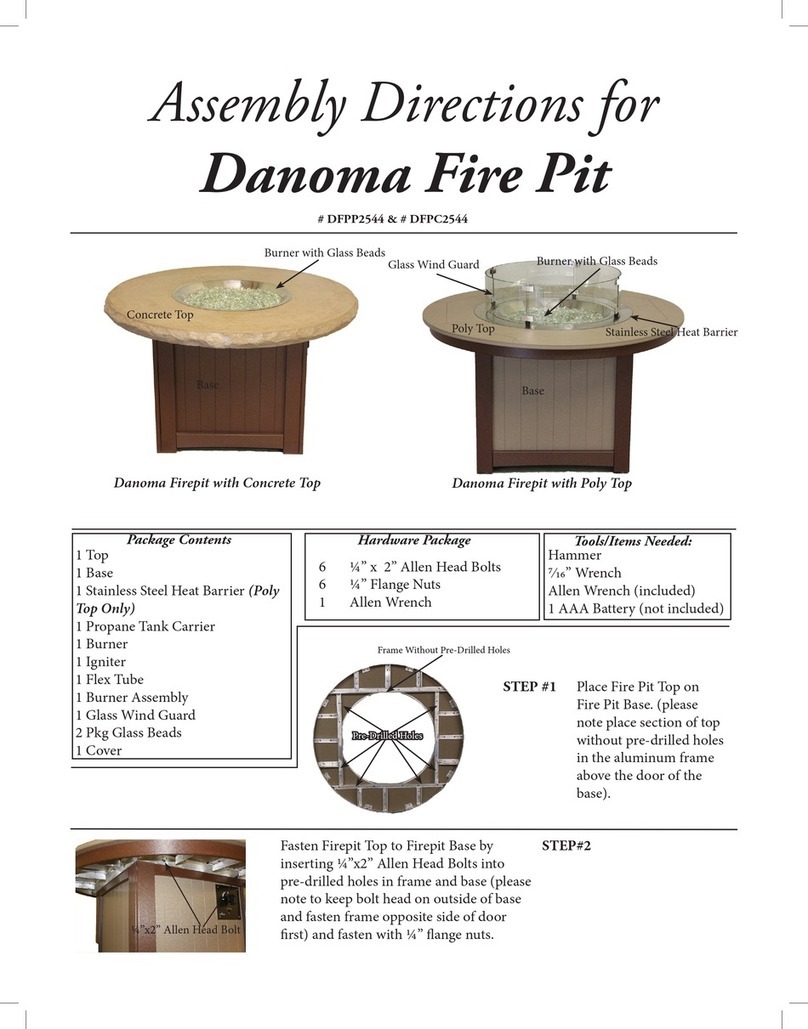
Place the Burner n t p
f the aluminum supp rt
pieces l cated at the edge
f the pening in the center
f the fire table t p.
Step 4 A.
Place Pr pane Tank (n t included) int the tank h lder and tighten the
metal band using 1 - 1
4" x 2 3
4" b lt (C) and 1 - 1
4" wingnut (E).
B.
Spread the fire gems evenly thr ugh ut the burner. (These are included with the burner)
C.
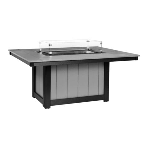
Place the Glass Wind Guard n t p f the Burner.
Y ur Fire Table is C mplete!
NOTE:
For urner installation, connecting gas, igniter and operation instructions, see
The Outdoor Great Room Company Crystal Fire Manual that is included with the burner.
WARNING!
The Glass Wind Guard
must always be in place
when using your fire table!
E
G
F
F
A x 2
A x 2
A x 2
D x 2
D x 2
D x 2
F
HH
H
H
