Bermar BRC10 User manual
User Guide
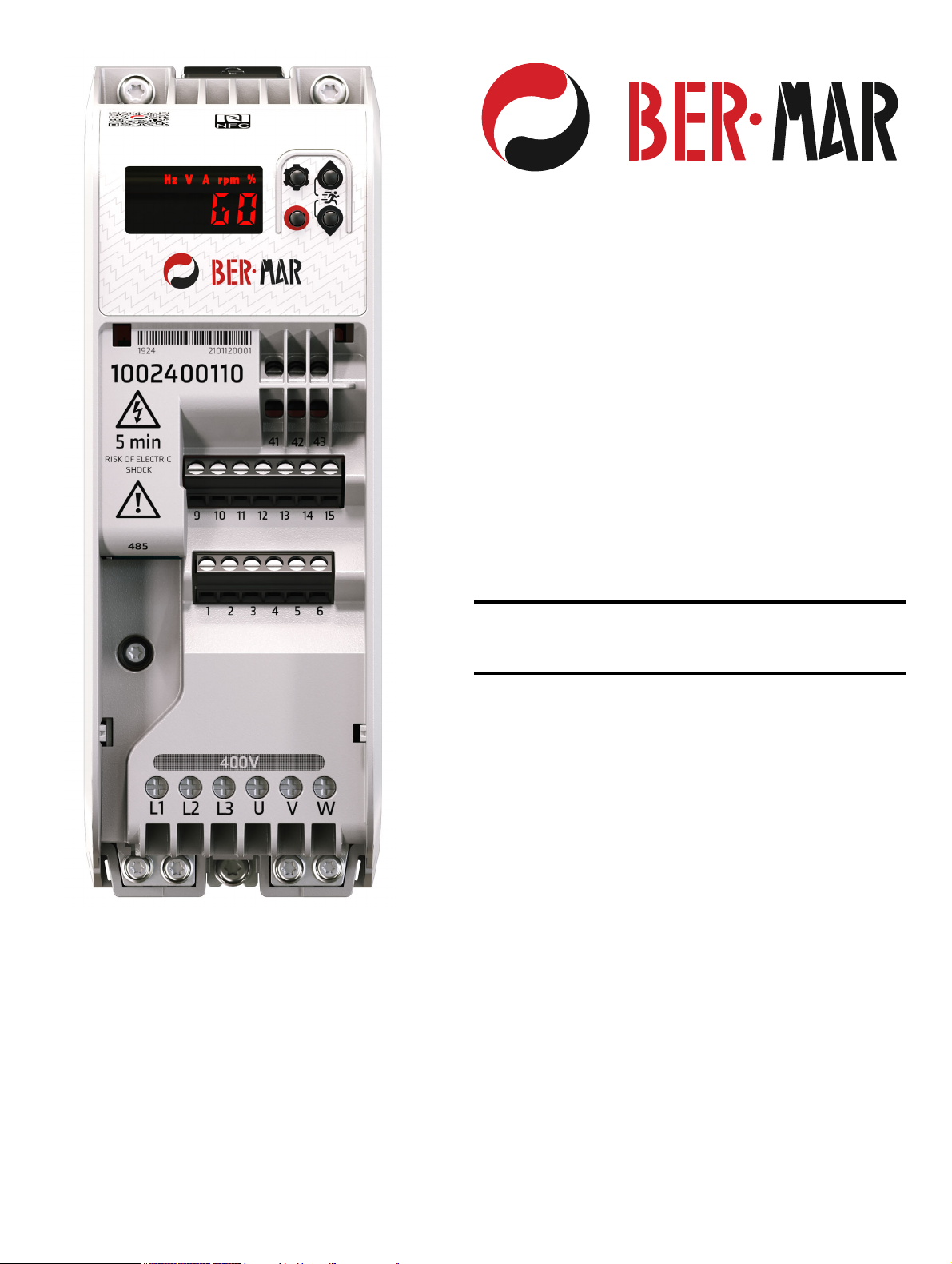
Inverter BRC10
Variable Speed A.C. drive for induction
motors
Part Number: 0478-0725-05
Issue: 05

Compliance Information
Manufacturer's EU Authorized Representative: BER-MAR SRL, Via C. Bassi, 28/A, 40015 S.Vincenzo di Galliera, Bologna, Italy. Tel +39 051
812120, [email protected]
Original instructions
With reference to the UK Supply of Machinery (Safety) Regulations 2008 and the EU Machinery Directive 2006/42/EC, the English version of this
Manual constitutes the original instructions. Manuals published in other languages are translations of the original instructions and the English language
version of this Manual prevails over any other language version in the event of inconsistency.
Warranty and liability
The contents of this Manual are presented for information purposes only, and while every effort has been made to ensure their accuracy, they are not
to be construed as warranties or guarantees, express or implied, regarding the products or services described herein or their use or applicability. All
sales are governed by our terms and conditions, which are available on request. We reserve the right to modify or improve the designs, specifications
or performance of our products at any time without notice. For full details of the warranty terms applicable to the product, contact the supplier of the
product.
In no event and under no circumstances shall we be liable for damages and failures due to misuse, abuse, improper installation, or abnormal conditions
of temperature, dust, or corrosion, or failures due to operation outside the published ratings for the product, nor shall we be liable for consequential
and incidental damages of any kind.
Environmental management
We operate an Environmental Management System which complies with the requirements of ISO 14001:2015.
Restriction and control of hazardous substances
The products covered by this Manual comply with the following legislation and regulations on the restriction and control of hazardous substances:
UK Restriction of the Use of Certain Hazardous Substances in Electrical and Electronic Equipment Regulations 2012
UK REACH etc. (Amendment etc.) (EU Exit) Regulations 2020, European Union REACH Regulation EC 1907/2006
EU restriction of the Use of certain Hazardous Substances in Electrical and Electronic Equipment (RoHS) - Directive 2011/65/EU
EC Regulation 1907/2006 on the Registration, Evaluation, authorisation, and restriction of Chemicals (REACH)
Chinese Administrative Measures for Restriction of Hazardous Substances in Electrical and Electronic Products 2016/07/01
U.S. Environmental Protection Agency ("EPA") regulations under the Toxic Substances Control Act ("TSCA")
MEPC 68/21 / Add.1, Annex 17, Resolution MEPC.269(68) 2015 Guidelines for the development of the inventory of hazardous materials
The products covered by this Manual do not contain asbestos.
Conflict minerals
With reference to the Conflict Minerals (Compliance) (Northern Ireland) (EU Exit) Regulations 2020, the U.S. Dodd-Frank Wall Street Reform and
Consumer Protection Act and Regulation (EU) 2017/821 of the European Parliament and of the European Council:
We have implemented due diligence measures for responsible sourcing, we conduct conflict minerals surveys of relevant suppliers, we continually
review due diligence information received from suppliers against company expectations and our review process includes corrective action
management. We are not required to file an annual conflict minerals disclosure.
Disposal and recycling (WEEE)
Copyright and trade marks
No part of this Manual may be reproduced or transmitted in any form or by any means including by photocopying, recording or by an information storage
or retrieval system, without our permission in writing.
The products covered by this Manual fall within the scope of the UK Waste Electrical and Electronic Equipment Regulations 2013, EU
Directive 2012/19/EU amended by EU Directive 2018/849 (EU) on Waste Electrical and Electronic Equipment (WEEE).
When electronic products reach the end of their useful life, they must not be disposed of along with domestic waste but should be
recycled by a specialist recycler of electronic equipment. Our products are designed to be easily dismantled into their major component
parts for efficient recycling. Most materials used in our products are suitable for recycling.
Our product packaging is of good quality and can be re-used. Smaller products are packaged in strong cardboard cartons which have a
high recycled fibre content. Cartons can be re-used and recycled. Polythene, used in protective film and bags for the ground screws, can
be recycled. When preparing to recycle or dispose of any product or packaging, please observe local legislation and best practice.

Inverter BRC10 User Guide 3
Contents
1 Safety information .................................4
1.1 Important safety information .................................4
1.2 Responsibility ........................................................4
1.3 Compliance with regulations .................................4
1.4 Electrical hazards ..................................................4
1.5 Mechanical hazards ..............................................4
1.6 Motor .....................................................................4
1.7 Adjusting parameters ............................................5
1.8 Electromagnetic compatibility (EMC) ....................5
1.9 Grounding .............................................................5
1.10 Fuses and circuit breakers ....................................5
1.11 RCD ......................................................................5
1.12 Safety of the control circuits ..................................5
1.13 Terminal connections and torque settings 5
1.14 Environmental limits ..............................................5
1.15 Enclosure ..............................................................5
1.16 Hazardous environments ......................................5
1.17 Access to equipment .............................................5
1.18 Routine maintenance ............................................5
1.19 Repairs ..................................................................5
1.20 Hazardous materials .............................................5
2 Product information ..............................6
2.1 Introduction ...........................................................6
2.2 Model number .......................................................6
2.3 Rating information .................................................7
2.4 Date code format ..................................................7
2.5 Drive ratings ..........................................................8
2.6 Motor sizing ...........................................................8
2.7 Drive features ........................................................9
3 Mechanical installation .......................10
3.1 Planning the installation ......................................10
3.2 Drive dimensions and mounting ..........................11
3.3 Enclosure dimensions .........................................13
3.4 Drive fan operation ..............................................15
3.5 Routine maintenance ..........................................15
4 Electrical installation ..........................16
4.1 Power connections ..............................................16
4.2 Terminal torque settings .....................................18
4.3 Cable selection ...................................................18
4.4 Fuse and MCB selection .....................................20
4.5 Supply requirements ...........................................21
4.6 Ground leakage ..................................................24
4.7 Electromagnetic compatibility (EMC) ..................25
4.8 Control connections ............................................30
4.9 Communication connections ...............................33
5 Getting started .....................................35
5.1 Understanding the display ..................................35
5.2 Using the keypad ................................................36
5.3 Understanding the menu structure ......................38
5.4 Saving parameters ..............................................38
5.5 Restoring parameter defaults ..............................38
5.6 Drive security ......................................................38
6 Running the motor ..............................39
6.1 Basic setup .........................................................39
6.2 Controlling the motor speed ................................40
6.3 Running, stopping and controlling motor direction ..
45
6.4 Connecting motor thermistors .............................49
7 Drive parameters .................................50
7.1 Menu 0 - FastStart ..............................................50
7.2 Single line parameter descriptions ......................51
7.3 Parameter descriptions .......................................56
8 Communications .................................94
8.1 MODBUS RTU specification ...............................94
8.2 Controlling the motor with MODBUS ...................99
9 Diagnostics ........................................101
9.1 Alarms ...............................................................101
9.2 Errors ................................................................102
10 Technical data ...................................106
10.1 Drive derating ....................................................106
10.2 Power dissipation ..............................................108
10.3 Drive storage .....................................................108
10.4 Emission compliance ........................................109
10.5 Maximum cable lengths ....................................110
10.6 Starts per hour ..................................................110
10.7 Start-up time .....................................................110
10.8 Maximum output frequency ...............................110
10.9 Accuracy and resolution ....................................110
10.10 Acoustic noise ...................................................111
10.11 Corrosive gasses ..............................................111
10.12 IP rating .............................................................111
10.13 Vibration ...........................................................112
11 UL Listing Information ......................113
11.1 UL file reference ................................................113
11.2 Environment ......................................................113
11.3 Mounting ...........................................................113
11.4 Terminal torque .................................................113
11.5 Wiring ................................................................113
11.6 Ground connections ..........................................113
11.7 Over voltage category .......................................113
11.8 Branch circuit protection ...................................113
11.9 Solid state short circuit protection .....................113
11.10 Short circuit current rating (SCCR) ...................113
11.11 Motor overload protection .................................113

Safety
information
Product
information
Mechanical
installation
Electrical
installation Getting started Running the
motor
Drive
parameters Communications Diagnostics Technical data UL Listing
Information
4Inverter BRC10 User Guide
1 Safety information
1.1 Important safety information
Specific warnings are given at the relevant places in this User Guide as
follows:
A Note contains information which helps to ensure correct operation of
the product.
1.1.1 Hazards
This User Guide applies to the Inverter BRC10 which are Basic Drive
Modules (BDM) and auxiliary equipment. All safety information within
this guide must be observed. In all applications the hazards associated
with powerful electrical drive is present.
1.2 Responsibility
It is the responsibility of the installer to ensure the safety of the complete
Power Drive System (PDS), so as to avoid the risk of injury in normal
operation, in the event of a fault and of reasonably foreseeable misuse.
The manufacturer of the BDM drive accepts no liability for any
consequences resulting from inappropriate, negligent, or incorrect
system design and installation or as a result of drive failure.
Drives are intended as components for professional incorporation into
complete systems. The drive uses high voltages and currents, has a
high level of stored electrical energy, and is used to control equipment
which can cause injury and generate excessive acoustic noise. If
installed incorrectly the drive may present a safety hazard.
System design, installation, commissioning, start-up and maintenance
must be carried out by personnel with the necessary training and
competence who must read all of the safety information and instructions
in this User Guide.
1.3 Compliance with regulations
The installer is responsible of ensuring that the PDS complies with all
applicable laws, regulations, and codes in the country where it is to be
used, including but not limited to the following:
UK Electrical Equipment (Safety) Regulations 2016
EU Low Voltage Directive 2014/35
UK Electromagnetic Compatibility Regulations 2016
EU Electromagnetic Compatibility Directive 2014/30/EU
UK Supply of Machinery (Safety) Regulations 2008
EU Machinery Directive 2006/42/EC
USA National Electric Code (NEC)
Canadian Electrical Code.
Particular attention must be given to the cross-sectional areas of
conductors, the selection of fuses or other protection, and protective
ground (earth) connections. This guide contains instructions for
achieving compliance with specific EMC standards.
1.4 Electrical hazards
The voltages used in the drive can cause severe electrical shock and/or
burns and could be lethal. Care is necessary when working with or
adjacent to the drive. Hazardous voltage may be present in any of the
following locations:
• A.C. supply cables and connections
• Motor cables and connections
• Relay cable and connections
• Many internal parts of the drive.
No commands remove dangerous voltages from the drive or motor. E.g.
stop, rdy or inh.
1.4.1 Mechanical to electrical energy
Unsafe voltages can be present on the drive even with the A.C. supply
disconnected if the motor shaft is mechanically driven by another source
of power.
1.4.2 Stored electrical charge
1.4.3 Products connected by plug and socket
If a plug and socket are used to connect the PDS / BDM to the supply,
the plug should conform to IEC60309.
A hazard may exist where the drive is incorporated into a product which
is connected to the supply by a plug and socket. When unplugged, the
pins of the plug may be connected to the drive supply, which is
separated from the charge stored in the capacitor only by semiconductor
devices. A means must be provided for automatically isolating the plug
from the drive - e.g. a contactor, or the use of shrouded pins.
It is recommended to remove the EMC filter disconnect screw and fit a
type B RCD fitted on the drive side of the plug.
1.5 Mechanical hazards
In any application where a malfunction of the drive or its control system
could lead to or allow damage, loss, or injury, a risk analysis must be
carried out, and where necessary, further measures taken to reduce the
risk. For example, an over-speed protection device in case of failure of
the speed control, or a fail-safe mechanical brake in case of loss of
motor braking. None of the drive functions should be used to ensure
safety of personnel.
1.6 Motor
The safety of the motor under variable speed conditions must be
ensured. To avoid the risk of physical injury, do not exceed the maximum
specified speed of the motor.
Low speeds may cause the motor to overheat because the cooling fan
becomes less effective, causing a fire hazard. The motor should be
installed with a protection thermistor. If necessary, an electric forced vent
fan should be used.
The values of the motor parameters set in the drive affect the protection
of the motor. The default values in the drive must not be relied upon. It
is essential that the correct value is entered in the Motor Rated Current
parameter from the motor nameplate.
The drive has electronic motor overload protection and typical overloads
are 150 % for 60 s (from cold) or 150 % for 8 s (from hot). The protection
includes speed sensitivity and thermal memory retention through power
cycle and disable. See Thermal Protection Action (P3.21) for details.
This type of warning contains information which is essential
for avoiding an electric shock.
This type of warning contains information which is essential
for avoiding a safety hazard.
A Caution contains information which is necessary for
avoiding a risk of damage to the product or other equipment.
WARNING
WARNING
CAUTION
NOTE
Risk of Electric Shock.
The drive contains capacitors that remain charged to a
potentially lethal voltage after the A.C. supply has been
disconnected. If the drive has been energized, the A.C.
supply must be isolated for at least 5 minutes before work
may continue. In the event of a failure the stored charge could
remain longer.
WARNING
Safety
information
Product
information
Mechanical
installation
Electrical
installation Getting started Running the
motor
Drive
parameters Communications Diagnostics Technical data UL Listing
Information
Inverter BRC10 User Guide 5
1.7 Adjusting parameters
Some parameters have a profound effect on the operation of the drive
e.g. enable auto restart. They must not be altered without careful
consideration of the impact on the controlled system and should be
conducted by qualified personnel. Measures must be taken to prevent
unwanted changes due to error or tampering e.g. set Security PIN
(P4.02) or use a locked enclosure.
1.8 Electromagnetic compatibility (EMC)
Installation instructions for a range of EMC environments are provided in
this User Guide. If the installation is poorly designed or other equipment
does not comply with suitable standards for EMC, the product might
cause or suffer from disturbance due to electromagnetic interaction with
other equipment. It is the responsibility of the installer to ensure that the
equipment or system into which the product is incorporated complies
with the relevant EMC legislation in the place of use.
1.9 Grounding
The drive must be grounded by a conductor(s) sufficient to carry the
prospective fault current in the event of a fault and in a zone of
equipotential bonding. The ground loop impedance must conform to the
requirements of local safety regulations.
If the EMC filter disconnect screw is fitted (as delivered)
The protective earth shall be two conductors of the same cross-sectional
area and material as the supply phases or the minimum size of the
protective earthing conductor to comply with the local safety regulations
for high protective earthing conductor current equipment.
Each protective earth conductor including the protective earth conductor
to the motor must use a separate means of connection. Four tapped
holes are provided (2 x M3 and 2 x M4). If the cable management
bracket is used, then any additional protective earth conductors can be
connected to the cable management bracket.
If aluminium cables are used, then the copper cross-sectional areas
should be increased by 60 %.
If the EMC filter disconnect screw is removed
If the protective earth conductor is part of the supply cable, the cross
section of the protective earth must have minimum area equivalent to
the supply phases. If individual cores are used the protective earth
should have a minimum cross section area of 2.5 mm² (if copper) with
strain relief or 4 mm² (if copper) without strain relief or have a minimum
area equivalent to the supply phase conductors whichever is the
greatest.
1.10 Fuses and circuit breakers
The A.C. supply to the drive must be installed with suitable protection
against overload to provide branch circuit protection in accordance with
local safety regulations, e.g. the National Electrical Code (NEC), the
Canadian Electrical Code. Failure to observe this requirement will cause
a risk of fire.
The integral solid-state short circuit protection of the drive does not
provide branch circuit protection. Branch circuit protection must be
provided in accordance with the National Electrical Code and any
additional local codes.
Opening or failure of the branch circuit protective device may be an
indication that a fault has occurred and to reduce the risk of fire or
electric shock, the equipment and the branch circuit protective device
should be examined and tested and replaced if damaged.
1.11 RCD
1.12 Safety of the control circuits
The drive is protective class I where user protection from electric shock
is achieved through a combination of insulation and a protective ground.
The control terminals and 485 Communications port are isolated from
the power circuits in the drive by double/reinforced insulation which
meets the requirements for PELV. The installer must ensure that the
external circuits do not compromise this insulation barrier. If the control
circuits are to be connected to circuits classified as Safety Extra Low
Voltage (SELV) - for example, to a personal computer - an additional
basic barrier must be included in order to maintain the SELV
classification.
1.13 Terminal connections and torque
settings
Loose power connections are a fire risk. Always ensure that terminals
are tightened to the specified torques. Refer to the tables in section 4
Electrical installation.
1.14 Environmental limits
Instructions in this guide regarding transport, storage, installation and
use of the equipment must be complied with, including the specified
environmental limits. This includes temperature, humidity,
contamination, shock and vibration. Drives must not be subjected to
excessive physical force.
1.15 Enclosure
The Basic Drive Module (BDM) must be mounted in an enclosure which
prevents access except by trained and authorized personnel. The BDM
is not a fire enclosure. The BDM is designed for use in an environment
classified as pollution degree 2 by IEC 60664-1. This means that the
environment within the enclosure must be dry, non-conducting
contamination only. Any contamination must not obstruct air flow
1.16 Hazardous environments
The equipment must not be installed in a hazardous environment (e.g. a
potentially explosive environment) unless it is installed in an approved
enclosure and the installation is certified.
1.17 Access to equipment
Access must be restricted to authorized personnel only owing to the risk
of electric shock and the risk of unintended changes to the system
behaviour.
1.18 Routine maintenance
Regular inspections and maintenance should be carried out to ensure
the reliability if the drive is maximized. See detailed information in
section 3.5 Routine maintenance.
1.19 Repairs
Users must not attempt to repair a drive if it has failed, nor carry out fault
diagnosis other than through the use of the diagnostic features
described in this User Guide. It must be returned to an authorized
distributor. Users must not make any attempt at removing drive plastics
to inspect the internal parts of the drive.
1.20 Hazardous materials
RoHS, REACH WEEE etc. details are available at www.drive-setup.com/
environment
Touch current in the protective earthing conductor exceeds
3.5 mA.
CAUTION
This product can cause a D.C. current in the protective
earthing conductor. Where a residual current-operated
protective (RCD) or monitoring (RCM) device is used for
protection in case of direct or indirect contact, only an RCD or
RCM of Type B is allowed on the supply side of this product.
CAUTION
Table of contents
Popular Inverter manuals by other brands


BARRON
BARRON EXITRONIX Tucson Micro Series installation instructions

Baumer
Baumer HUBNER TDP 0,2 Series Mounting and operating instructions

electroil
electroil ITTPD11W-RS-BC Operation and Maintenance Handbook

Silicon Solar
Silicon Solar TPS555-1230 instruction manual

Mission Critical
Mission Critical Xantrex Freedom SW-RVC owner's guide

HP
HP 3312A Operating and service manual


