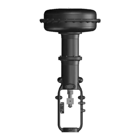
Bernard Controls FSE Series User guide

FSE
RANGE
Start Up Guide
SUG_19002_EN - Ind. A
Art : 5100705
avrora-arm.ru
+7 (495) 956-62-18

English
3
TABLE OF CONTENTS
Definitions ---------------------------------------------------------------------5
Introduction -------------------------------------------------------------6
Safety information 8
Specifications of the actuator 13
Identifying Actuator Parts 14
Installation and mounting information 15
Service information 17
Identification of FSE actuator 19
OPERATION ------------------------------------------------------------ 20
Modulation and configuration of FSE for ON/OFF application 23
Home Screen 23
Basic Setup 25
Advance Setup 39
Operation by Hydraulic Manual Override 61
Adjustment for limit switches 64
Open Switch Adjustment 65
Close Switch Adjustment 65
Open and close indicators 65
Removal of terminal block and Cable Connections------------- 66
Removal of terminal cover 66
FSE for ON/OFF Application ---------------------------------------- 68
Preconditions 68
Description 68
Operation 68

English
4
Maintenance and Troubleshooting--------------------------------- 72
General maintenance 72
Replacement of the filter 73
Replacement of the hydraulic fluid 74

English
5
Definitions
NOTE:
Advisory and information comments provided to assist
maintenance personnel to carry out maintenance procedures.
WARNING
If not observed, user incurs a high risk of severe damage to
product and/or fatal injury to personnel.
!
CAUTION
If not observed, user may incur damage to product and/or injury
to personnel.

English
6
Introduction
Thank you for choosing BERNARD CONTROLS product. FSE range
Actuators are self-contained; electro-hydraulic actuators which are
particularly well suited for applications requiring critical control and
high reliability.
There are two major components to the FSE range:
the actuator which mounts onto the driven device (a valve),
consists of the cylinder (in case of double acting) or cylinder
with spring module (in case of single acting) ;
the electronic control module which consists of feedback
module, electronics, hydraulic tank, motor & power supply.
This combination of mechanical, hydraulic and electronic
technologies produces actuators that ensure our customers get
top class actuating.
The actuator is constructed for direct mounting on valves according
to ISO-standards.
All electronics are protected in watertight or explosion-proof
enclosure. FSE range Actuators is available in double acting or spring
return configurations for quarter turn applications. They can be
configured to mount in any position, including remote mounting of
control module. Torque requirements up to 600,000 N∙m can be
accommodated.
FSE range includes local manual control, indication feedback via dry
contacts and 4-20mA feedback signal; or optional digital control via
Modbus, Foundation Fieldbus, Profibus or DeviceNet. FSE range can
be supplied for operation with any single phase, three phases or
24VDC power supply.
Each product is fully inspected after the production to offer you the
highest quality. In order to fully utilize the product, we strongly
recommend users to read this manual carefully and understood.

English
7
This manual provides information on installation, operation and
maintenance and related instructions for the BERNARD CONTROLS
electro-hydraulic actuator (FSE).
The aim of this literature is to support the use of products in
correct manner, and all the technical information provided in
the catalogue.
The manual should be given to the end user.
The manual can be changed or revised without any prior
notice. Any changes in product's specification, structure,
and/or any components may not result in immediate revised
version of the manual.
The manual should not be duplicated or reproduced for any
purpose without any consent from BERNARD CONTROLS.
Manufacturer Warranty
For the safety, it is vital to follow instructions in the manual.
It is not BERNARD CONTROLS’s liability for any damages which
caused by users' negligence.
It is not BERNARD CONTROLS's liability for any damages or
accidents which resulted by any alteration or modification of
the product and parts. If alteration or modification is
necessary, please contact BERNARD CONTROLS directly.
BERNARD CONTROLS warrants the product from the date of
original retail purchase of the product for one (1) year, except
otherwise stated.
BERNARD CONTROLS warranty will not cover the products that
have been subjected to abuse, accident, alteration,
modification, tampering, negligence, misuse, faulty
installation, lack of reasonable care, repair or service in any
way that is not contemplated in the documentation for the
product, or if the model or serial number has been altered,
tampered with, defaced or removed; damages that occurs in
shipment, failure due to power surge, and cosmetic damage.
Improper or incorrectly performed maintenance or report
voids this Limited Warranty.
For detailed warranty information, please contact BERNARD
CONTROLS

English
8
Safety information
!
READ THESE INSTRUCTIONS CAREFULLY BEFORE INSTALLING
AND USING THE PRODUCT
Products supplied by BERNARD CONTROLS, in its "as shipped"
condition, are intrinsically safe if the instructions contained within
this Service Instruction are strictly adhered to and executed by well-
trained, equipped, prepared and competent personnel.
The following documents should also be consulted:
a) IEC/EN60079-14 standard (electric installations in gaseous
explosive atmosphere),
b) IEC/EN60079-17 standard (inspection and maintenance
operations in dangerous areas),
c) Decrees, ministerial orders, laws, directives, standards,
procedures and any other document relative to the area where
the actuator has to be installed.
BERNARD CONTROLS S.A. or BERNARD CONTROLS Inc. cannot be
judged responsible for the non-respect of these rules.
Our equipment complies with IECEx and ATEX Standard and is
therefore IECEx and ATEX marked.
They have been designed to be used in explosive atmospheres:
Group II - category 2 in presence of vapor, fog or gas (G).
Use in zone 1 or 2 for gas
Please check the compatibility between the indications written on
the identification plate and the explosive atmosphere type, the
ambient and the admissible surface temperature of the installation
area.
The actuator installation and maintenance must be carried out by
qualified, trained and certified personnel.
Please carefully read this whole document before mounting and
starting-up the actuator.

English
9
Marking
ATEX
Explosionproof
enclosure “d”
IECEx
Explosionproof
enclosure “d”
Name and
address of the
manufacturer
BERNARD CONTROLS
4 rue d’Arsonval - 95505 Gonesse France
Actuator type
FSE
Serial number
Serial n°YYAXXXXX.ZZZ
Serial n° n°YYAXXXXX.ZZZ
Certificate
number
Pending
Pending
Specific
marking
-
-
N° of notified
audit body
1354
1354
Gas marking
Ex db h IIB T5 Gb
Ex db h IIB T5 Gb
Dust marking
Ex h tb IIIB T100°C Db IP65
Ex h tb IIIB T100°C Db IP65
Ambiant
temperature
-20°C +60°C
-20°C +60°C

English
10
Start-up
!
WARNING –DO NOT OPEN WHEN AN EXPLOSIVE ATMOSPHERE IS
PRESENT
To avoid any risk of explosion, the actuator electric control and
power supply must be switched off before opening the cover.
Be careful not to damage the joint surfaces of the cover
either at the opening and closing of the cover, when
repositioning the cover onto the actuator body.
When closing the cover, check the joints cleanliness.
Tighten each cover screw.
The fastening screws shall be stainless steel socket head cap screws
of property class A2-70 and yield stress 450 MPa.
In case of use in explosive dust atmosphere, check that cover
tightness gaskets are intact and make sure not to degrade the
gaskets while closing the cover.
Cable entries shall provide a level of protection equal or higher than
the one indicated on the actuator identification plate. Only suitable
certified Ex db, Ex tb IP 65 cable gland to be used. If one of them is
not used, seal it with a certified and suitable metal plug for the type
of protection specified.
A connection to the earth must be wired using the actuator external
grounding plug. Internal and external groundings must be connected.
Remove all plastic plugs of unused conduit entries and replace
by a certified metal plug. Plastic plugs are not explosion-proof
and are used for shipping only.
Cable glands or Conduit entries
Plug
5 threads
minimum
5 threads
minimum

English
11
Waterproofness
Because the NPT cable gland thread is not IP68, it’s necessary to
mount it with a thread sealant for ex: Loctite 577 (Henkel). In case
of ISO thread, sealing is assured by an O-ring or by a thread sealant
as noticed above.
Operation
Never leave the cover open, in order to avoid any risk of water
inlet.
In case of use in explosive dust atmosphere, check that cover
tightness O-rings are intact and make sure not to damage the seals
while closing the cover.
Maintenance
Regularly check that the actuator explosion-proof enclosure has not
been degraded by a mechanical shock or any other type of
aggression.
Do not bring any modification of any kind to the actuator.
The user shall ensure a regular cleaning of the product housing to
avoid dust build-up. Wipe surface of polycarbonate indicator cover
used for indicator with moist/wet cloth.
The actuator mechanical parts are greased and do not need any
specific maintenance. In case of a disassembly/re-assembly
operation, make sure that all moving parts are correctly greased in
order to prevent any electric spark.
User must refer to the manufacturer before carrying out any repairs
or refurbishment to the equipment.
The gap specified in the approved drawing must never be exceeded.

English
12
Installation area
This actuator is an explosion-proof equipment and can be used in the
following areas:
Protection
class
Category
Division
Atmosphere
Ex db, Ex tb
2 (EPL Gb/Db)
Zone 1 or 2
G Gas / D Dust
EPL (Equipment Protection Level): b=high level Gas (G) and Dust (D).
Zone 1 (gas) & 21 (dust): the explosive atmosphere is likely to occur
occasionally in normal operation.
Zone 2 (gas) & 22 (dust): the explosive atmosphere is not likely to
occur in normal operation but if it does occur, it will persist for
a short period of time only.
!
This device has not been designed to be operated in an area
where explosive atmosphere occurs frequently or during long
periods (IEC 60079-10-1-zone 0).
Groups
This actuator has been designed for the surface industries.
Zone Group
Typical atmosphere
IIB
Ethylene
IIIB
Flamable dust
For other gases, please consult a notified body.
Temperature
The temperature class corresponds to the actuator maximum surface
temperature.
Class
Max surface temperature
T5
100°C
Check group and temperature class on the actuator tag.

English
13
Special operation conditions including incorrect practices
Covers opening
Removing the covers is authorized only when the actuator power
supply is switched off and no explosive atmosphere is present. It is
important not to degrade the explosion-proof protections (surfaces,
cable entries, joints ...). Use the notches or bosses in order to keep
seals and cover integrity.
Specifications of the actuator
Enclosure
The design of self-contained electrohydraulic actuator(FSE)/electric
fail safe actuator construction conforms to EN 60079-
0:2012+A11:2013; EN 60079-1:2014; EN 60079-31:2014 for gas group
IIB, dust group IIIB and ingress protection of IP65 as per IS/IEC
60529:2001.
The FSE has been built in accordance with the following standards:
IEC 61508:2010 ; SIL3 Capable
Ambient Temperature Range
T amb. = -20 °C to +60 °C
Enclosure Materials
Main body: Cast Aluminum alloy LM6 ;
ON /OFF Indicator dome –Polycarbonate and ABS.

English
14
Identifying Actuator Parts

English
15
Installation and mounting information
WARNING
For the protection of personnel working on BERNARD CONTROLS
actuators, this procedure should be reviewed and implemented for
safe installation, disassembly and reassembly. Close attention
should be noted to the WARNINGS, CAUTIONS and NOTES contained
in this procedure.
FSE actuators allow many
different mounting
orientations. However it
is NOT permitted to
mount the FSE assembly
vertically as the motor
becomes inline directly
beneath the oil tank as
shown in figure.
Ensure that the actuator will not be exposed to pressure in
excess to the maximum rating as indicated on the actuator
nameplate or technical documents.
Ensure that the valve is secure before fitting the actuator as
the combination may be top heavy and therefore unstable.
Ensure that throughout the installation that there are no leaks
of the supply media.
Ensure that the maximum operating temperature as indicated
on the nameplate is not exceeded during operation,
transportation or storage of the actuator.
The environment and surrounding should not affect or limit the
operational safety of the product.
Product should not be installed in hazardous area that is not
compatible with the gas group and temperature class indicated
on the nameplate.

English
16
If it is necessary to lift the FSE assembly, then use certified
slings to lift the FSE assembly with the help of lifting eyebolts
as shown in the figure.
WARNING
Use the lifting eye bolts for lifting the FSE assembly only.
Valve installation: Before fitting an actuator onto a valve,
care to be taken to ascertain the position of the valve and
orientation of the actuator accordingly.
While bolting the actuator to the valve flange; the position of the
stop bolts should be checked to ensure full opening and closing of
the valve. If the end positions are not suitable, the stop bolts may be
adjusted by loosening and screwing the bolts properly until desired
position is obtained. When desired position is obtained; retighten the
nuts.
Electrical Connections: Always refer to the job specific wiring
diagrams for connection instructions.

English
17
Service information
Normal recommended service interval for this actuator series is 5
years.
NOTE
Storage time is counted as part of the service interval.
This procedure is applicable with the understanding that all
hydraulic pressure has been removed from the actuator.
Remove all piping and mounted accessories that will interfere with
the module that are to be worked on.
Use a non-hardening thread sealant on all pipe threads.
All parts should be thoroughly inspected for excessive wear, stress
cracking and pitting. Attention should be directed to threads, sealing
surfaces and areas that will subjected to sliding and rotating motion.
BERNARD CONTROLS recommends that disassembly of the actuator
modules should be done in a clean area on a workbench.
Before installation on the valve, the actuator needs to be stroke for
several times to ensure the desired function and safety.
!
CAUTION
Apply the thread sealant as per the manufacturer’s instructions.

English
18
WARNING
Compressed Springs
All springs within the FSE range of actuators are pre-compressed.
Springs must not be removed from the actuator.
WARNING
Hydraulic Fluid
FSE actuators are filled with hydraulic fluid
Should there be a requirement to change the fluid, then first
ensure that the system is depressurized, and the appropriate
protective clothing including gloves and safety glasses are worn.
WARNING
Motor Temperature
Under normal operation the temperature of the actuator’s motor
cover surfaces can exceed 60 °C above ambient.
WARNING
Enclosure Materials
Power Unit: Aluminum
Display Window: Toughened Glass
External Fasteners: Stainless Steel-Class A2-70
Actuator Body: Aluminum
Drive Shaft: Stainless Steel
Piping: Stainless Steel
Paint Finish: PU type of 90 micron DFT

English
19
Identification of FSE actuator

English
20
OPERATION
Operation by the local and remote selector switch
Local/Remote Selection: Local/Remote selection is via two
rotary switches located on the control module. Rotate fully
anti-clockwise is the remote control position. Rotate fully
clockwise is the local control position. The mid position is
offline, prohibiting the local or remote control of the actuator.
When Remote/Local control is changed in the course of travel,
the actuator will stop in its current position until new
command is received.
Local Operation: The Local/Remote selector switch must be
pointing to Local position to manually operate the actuator.
The Open/Close selector switch is disabled when the
Local/Remote selector switch is set for Remote operation.

English
21
Open/Close Selection: Open/Close selection is via another
rotary switch located on the control module. Rotate fully anti-
clockwise to open or clockwise to close from the centre detent
position. Direction of travel may be reversed during the
stroke.
Local position Indicator: Local position indication is available
via LCD display visible through a window in the control module
cover. The display is also used for configuration & fault
indication which will be discussed in the modulation and
configuration section.
Remote Operation: The Local/Remote selector switch must be
in the Remote position to operate the actuator remotely. The
open close selector switch is disabled when the Local/Remote
selector is set for Remote operation.
The local control of FSE actuator by rotary switches is as follows:
Red Rotary Switch
The RED switch is to
select the local
control, remote
control or offline
control of the
actuator.
In Local Control rotate
the red switch
clockwise to stop the
actuator and in
Remote Control rotate
the red switch
anticlockwise to stop the actuator.
Table of contents
Other Bernard Controls Controllers manuals
Bernard Controls
Bernard Controls AT SWITCH RANGE User guide

Bernard Controls
Bernard Controls EZ Series Instructions for use
Bernard Controls
Bernard Controls AQ SWITCH 150-1000 User guide
Bernard Controls
Bernard Controls ST Series Installation manual
Bernard Controls
Bernard Controls AQ Logic Series User guide

Bernard Controls
Bernard Controls AQ Logic Series User guide
Bernard Controls
Bernard Controls Gamme FQ Series Installation manual
Bernard Controls
Bernard Controls AQL Range User guide
Bernard Controls
Bernard Controls SD Series Instructions for use
Bernard Controls
Bernard Controls SQX Series Installation manual
