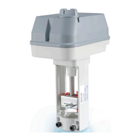
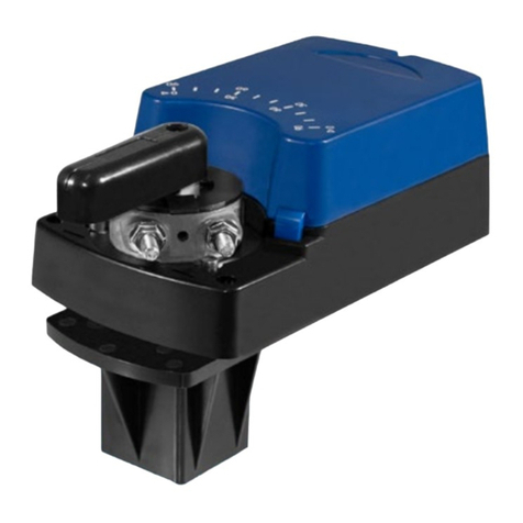
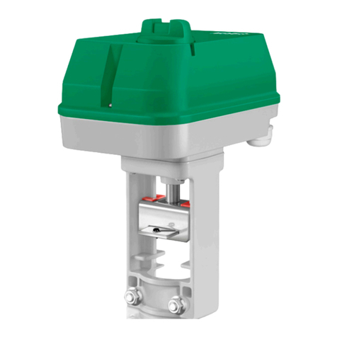
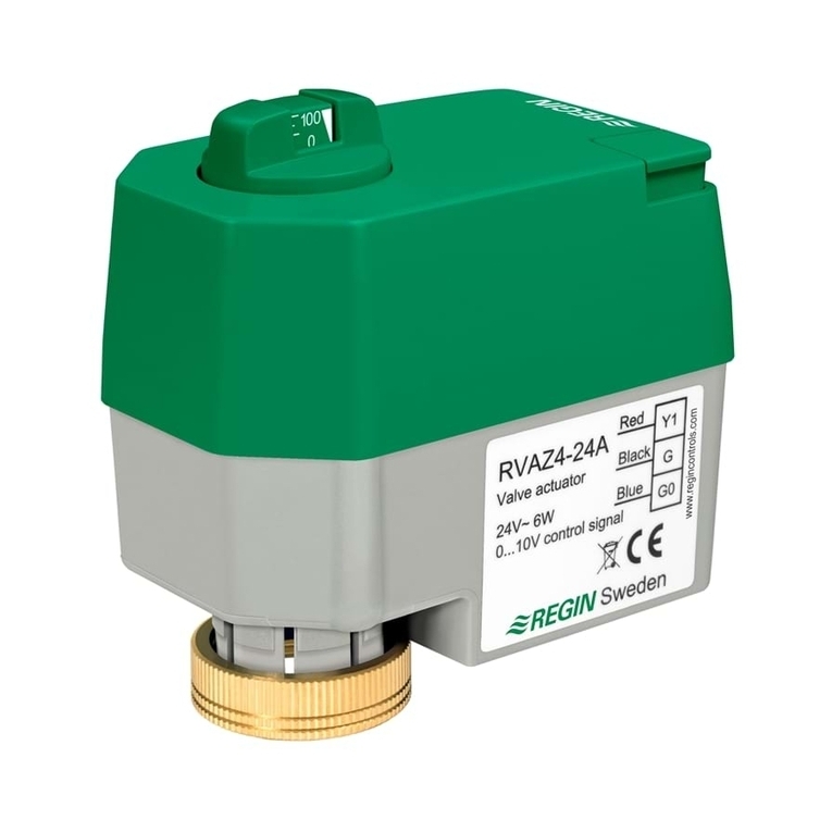
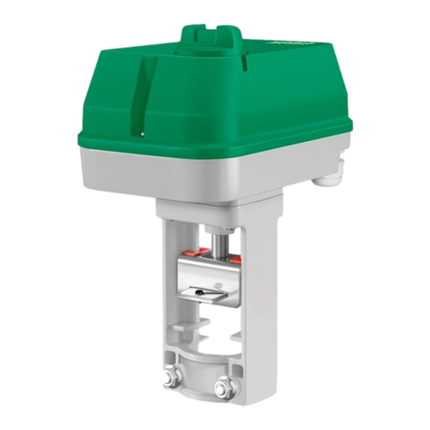
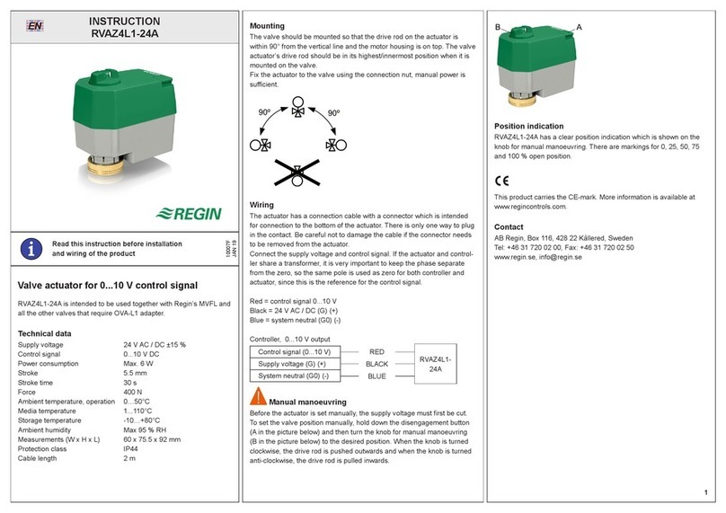
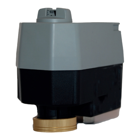
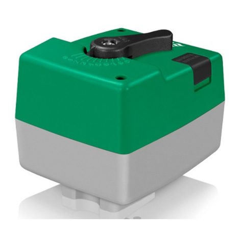
Regin RVAZ4-24A User manual

INSTRUCTION
i
Read this instruction before installation
and wiring of the product
Valve actuator for 0...10 V control signal
RVAZ4-24A is intended to be used together with Regin’s valves ZTV
and ZTR.
Technical data
Supply voltage 24 V AC ±15 %
Control signal 0...10 V DC
Power consumption Max 6 watts
Stroke 5.5 mm
Stroke time 30 s
Force 400 N
Ambient temperature, operation 0°C…50°C
Media temperature 1°C...110°C
Storage temperature -10°C…+80°C
Ambient humidity Max 95 % RH
Measurements (W x H x L) 60 x 75.5 x 92 mm
Protection class IP44
Mounting
The valve should be mounted so that the drive rod on the actuator is
within 85° from the vertical line and the motor housing is on top. The
valve actuator’s drive rod should be in its highest/innermost position when
it is mounted on the valve.
Fix the actuator to the valve using the connection nut, manual power is
sufcient.
85º
85º
Wiring
The actuator has a connection cable with a connector which is intended
for connection to the bottom of the actuator. There is only one way to plug
in the contact. Be careful not to damage the cable if the connector needs
to be removed from the actuator.
Connect the supply voltage and control signal. If the actuator and control-
ler share a transformer, it is very important to keep the phase separate
from the zero, so the same pole is used as zero for both controller and
actuator, since this is the reference for the control signal.
Red = control signal 0...10 V
Black = 24 V AC (G) (+)
Blue = system neutral (G0) (-)
Controller, 0...10 V output
Control signal (0...10 V)
Supply voltage (G)
System neutral (G0)
RED
BLACK
BLUE
RVAZ4-24A
Manual manoeuvring
To set the valve position manually, hold down the disengagement button
(A in the picture below) and then turn the knob for manual manoeuvring
(B in the picture below) to the desired position. When the knob is turned
clockwise, the drive rod is pushed outwards and when the knob is turned
anti-clockwise, the drive rod is pulled inwards. We recommend that the
supply voltage is cut before the actuator is set manually.
A
B
Position indication
RVAZ4-24A has a clear position indication which is shown on the
knob for manual manoeuvring. There are markings for 0, 25, 50, 75
and 100 % open position.
Automatic calibration
RVAZ4-24A has an automatic calibration function for adjustment of
zero point and stroke in order to adjust the 0...10 V control signal to
the valve. Calibration takes place each time power is connected.
EMC compatibility
This product conforms with the EMC requirements of European
harmonised standards EN60730-1:2000 and EN60730-2-8:2002 and
carries the CE mark.
Contact
AB Regin, Box 116, 428 22 Kållered, Sweden
Tel: +46 31 720 02 00, Fax: +46 31 720 02 50
www.regin.se, [email protected]
RVAZ4-24A
7433D
FEB 10
EN
1

i
Läs denna instruktion innan produkten
monteras och ansluts
INSTRUKTION
RVAZ4-24A
Ventilställdon för 0...10 V styrsignal
RVAZ4-24A är avsedd att användas tillsammans med Regins ventiler
ZTV och ZTR.
Tekniska data
Matningsspänning 24 V AC ±15 %
Styrsignal 0...10 V DC
Effektförbrukning Max 6 watt
Slaglängd 5,5 mm
Ställtid 30 s
Ställkraft 400 N
Omgivningstemperatur, drift 0°C…50°C
Mediatemperatur 1°C...110°C
Lagringstemperatur -10°C…+80°C
Omgivande luftfuktighet Max 95 % RH
Mått (B x H x L) 60 x 75,5 x 92 mm
Skyddsklass IP44
Montering
Ventilen ska monteras så att ställdonet hamnar med drivstången inom
85° från lodlinjen med motorhuset överst. Ventilställdonets drivstång
ska vara i sitt översta/innersta läge vid montering på ventilen.
Gänga fast ställdonet på ventilen med hjälp av förbindningsmuttern så
att ställdonet blir xerat till ventilen, det räcker att använda handkraft
vid xeringen.
85º
85º
Inkoppling
Ställdonet har en anslutningskabel med kontaktdon som är avsedd
för kontakteringen i ställdonets nederkant. Kontakten går bara att
sätta i på ett sätt. Var försiktig om kontaktdonet behöver tas loss från
ställdonet så att inte kabeln skadas.
2
Koppla in matningsspänning och styrsignal. Om ställdon och regulator
delar transformator är det mycket viktigt att hålla ordning på fas och nolla
så att samma pol används som nolla hos både regulator och ställdon
eftersom denna är referens för styrsignalen.
Röd = styrsignal 0...10 V
Svart = 24 V AC (G) (+)
Blå = systemnolla (G0) (-)
Regulator, 0...10 V-utgång
Styrsignal (0...10 V)
Matningsspänning (G)
Systemnoll (G0)
RÖD
SVART
BLÅ
RVAZ4-24A
Manuell manövrering
För att manuellt ställa in ventilpositionen, håll nere frikopplingsknappen (A
i nedanstående bild) och vrid sedan handmanövervredet till önskad
position (B i nedanstående bild). Vid medurs vridning skjuts drivstången
utåt och vid moturs vridning dras den inåt. Vi rekommenderar att
matningsspänningen bryts innan ställdonet ställs manuellt.
A
B
Lägesindikering
RVAZ4-24A har en tydlig lägesindikering som avläses på hand-
manövervredet. Det nns markeringar för 0, 25, 50, 75 och 100 % öppn-
ingsposition.
Automatisk kalibrering
RVAZ4-24A har automatisk kalibreringsfunktion för injustering av nollpunkt
och slaglängd för att anpassa 0...10 V styrsignal till ventilen. Kalibrering
sker vid varje spänningstillslag.
EMC-kompatibilitet
Produkten uppfyller EMC-kraven för europeiska harmoniserade
standard EN60730-1:2000 och EN60730-2-8:2002 och är CE-märkt.
Teknisk support
Teknisk hjälp och råd på telefon: 031 720 02 30
Kontakt
AB Regin, Box 116, 428 22 Kållered, Sweden
Tel: +46 31 720 02 00, Fax: +46 31 720 02 50
www.regin.se, [email protected]
SV

i
Lesen Sie diese Anleitung, bevor Sie das
Produkt installieren und anschließen
ANLEITUNG
RVAZ4-24A
Ventilstellantrieb für 0...10 V Stellsignal
RVAZ4-24A ist für den Gebrauch mit den Regin Ventilen ZTV und ZTR
vorgesehen.
Technische Daten
Versorgungsspannung 24 V AC ±15 %
Ansteuerung 0...10 V DC
Leistungsaufnahme Max 6 Watt
Hub 5,5 mm
Laufzeit 30 Sek.
Stellkraft 400 N
Betrieb 0°C…50°C
Medientemperatur 1°C...110°C
Lager und Transport -10°C…+80°C
Relative Feuchte Max 95 % RF
Abmessungen (B x H x T) 60 x 75,5 x 92 mm
Schutzart IP44
Montage
Das Ventil sollte so montiert werden, dass die Ventilspindel am Stell-
antrieb 85° von der vertikalen Linie entfernt und das Motorgehäuse
oben ist. Die Ventilspindel sollte sich bei der Montage in seiner
höchsten Position benden. Befestigen Sie den Stellantrieb mittels
Verbindungsschraube auf dem Ventil. Dies kann ganz leicht per Hand
durchgeführt werden.
85º
85º
DE Anschluss
Der Stellantrieb hat ein Anschlusskabel mit einem Verbindungsstück, das
am Unterteil des Stellantriebs angebracht wird. Der Kontakt muss richtig
gesteckt werden. Achten Sie darauf, das Kabel nicht beim Herausziehen
des Kontaktes zu beschädigen.
Schließen Sie die Versorgungsspannung und das Regelsignal an. Wird
für den Stellantrieb und den Regler der gleiche Trafo eingesetzt, muss der
Hauptleiter vom Masseanschluss getrennt sein. Der Regler und der Stell-
antrieb sollte den gleichen Masseanschluss haben, da er als Referenz für
das Regelsignal gilt.
Rot = Regelsignal 0...10 V
Schwarz = 24 V AC (G) (+)
Blau = Erde (G0) (-)
Regler, 0...10 V Ausgang
Regelsignal (0...10 V)
Versorg.spannung (G)
Erde (G0)
ROT
SCHWARZ
BLAU
RVAZ4-24A
Handbedienung
Um die Ventilposition manuell einzustellen, drücken Sie zuerst den
Auslöseknopf (A im unteren Bild) und drehen dann den Knopf für Hand-
bedienung (B im unteren Bild) bis zur gewünschten Position. Das Drehen
im Uhrzeigersinn bewegt die Ventilspindel nach oben. Das Drehen gegen
den Uhrzeigersinn bewegt die Ventilspindel nach unten. Wir empfehlen
Ihnen, die Versorgungsspannung vor der Handbedienung des Stell-
antriebs abzuschalten.
A
B
Stellungsanzeige
RVAZ4-24A hat eine Positions-LED, die auf dem Knopf für die Hand-
bedienung angebracht ist. Die Markierungen gelten für 0, 25, 50, 75 und
100% geöffnete Position.
Automatische Kalibrierfunktion
RVAZ4-24A hat eine automatische Kalibrierfunktion zur Einstellung
der beiden Endpunkte und des Hubweges, um das 0…10 V Stellsig-
nal an das Ventil anzupassen. Die Kalibrierung erfolgt nach jedem
Wiedereinschalten der Betriebsspannung.
EMC Konformität
Dieses Produkt entspricht den EMC-Richtlinienstandards und
EN60730-1:2000 und EN60730-2-8:2002 und trägt das CE-Zeichen.
Kontakt
AB Regin, Box 116, 428 22 Kållered, Schweden
Tel: +46 31 720 02 00, Fax: +46 31 720 02 50
www.regin.se, [email protected]
3

INSTRUCTION
i
Veuillez lire cette instruction avant de procéder à
l'installation et au raccordement de l'appareil.
RVAZ4-24A
Moteur de vanne pour contrôle 0...10 V
RVAZ4-24A est prévue pour être utilisée avec les actionneurs des gam-
mes ZTV et ZTR de Regin.
Caractéristiques techniques
Tension d’alimentation 24 V AC ±15 %
Signal de commande 0...10 V DC
Puissance consommée 6 W max.
Course 5,5 mm
Temps de course 30 s
Force 400 N
Température ambiante, fonctionnement 0 °C…50 °C
Température du uide 1 °C...110 °C
Température de stockage -10 °C…+80 °C
Humidité ambiante Max. 95 %HR
Dimensions (L x H x P) 60 x 75,5 x 92 mm
Indice de protection IP44
Montage
La vanne doit être montée de façon à ce que l’axe de l’actionneur
fasse au maximum un angle de 85° par rapport à la verticale et avec le
bloc moteur en haut. L'axe du moteur doit se trouver en position haute
(c.-à-d. rentré) pour permettre le montage sur la vanne.
Utiliser les écrous pour solidariser la vanne et le moteur. Il n'y a pas
besoin d'outils, la force manuelle suft.
85º
85º
Raccordement
Le moteur est équipé d'un câble avec un connecteur adapté qui est
destiné à être branché à la base de l'actionneur. Il n'y a qu'une seule
façon d'effectuer ce branchement. Attention à ne pas endommager le
câble lorsque vous débranchez le connecteur.
Branchez l'alimentation et le signal de commande. Si l’actionneur et le
régulateur sont alimentés par le même transformateur, il faut absolument
s’assurer que le neutre du transformateur soit bien relié avec le neutre de
chacun des autres appareils.
Rouge = signal de commande 0...10 V
Noir = 24 V AC (G) (+)
Bleu = neutre (G0) (-)
Régulateur, sortie 0...10 V
Sign. de commande (0...10 V)
Tension d’alimentation (G)
Neutre (G0)
ROUGE
NOIR
BLEU
RVAZ4-24A
Commande manuelle
Pour régler la position de la vanne manuellement, appuyez sur le bouton
A (voir image ci-dessous) et tournez le bouton B pour manœuvrer ma-
nuellement la vanne dans la position souhaitée.
Lorsque vous tournez le bouton B dans le sens des aiguilles d'une
montre, l'axe sort (la vanne s'ouvre) et lorsque vous tournez dans le sens
inverse des aiguilles d'une montre, l'axe rentre (la vanne se ferme).
Il est recommandé de couper le courant avant d'effectuer toute opération
de manœuvre manuelle de l'actionneur.
A
B
Indicateur de position
RVAZ4-24A est doté d'un indicateur de position situé sur le bouton B. Les
repères correspondent à 0, 25, 50, 75 et 100% d'ouverture de la vanne.
Réglage automatique de la course et du point de n de
course
RVAZ4-24A est doté d’une fonction d’ajustement automatique de la
course et du point de n de course, ce qui permet d’adapter le signal de
commande 0…10 V à la vanne.
Le réglage automatique se déclenche à chaque mise sous tension de
l’actionneur.
Directive compatibilité électromagnétique (CEM)
2004/108/EC
Ce produit est conforme aux exigences des standards CEM CE-
NELEC EN61000-6-3:2001 et EN61000-6-1:2001 et porte le mar-
quage CE.
Contact
AB Regin, Box 116, 428 22 Kållered, Suède
Tél : +46 31 720 02 00, Fax : +46 31 720 02 50
www.regin.se, [email protected]
FR
4
Table of contents
Languages:
Other Regin Controllers manuals

Regin
Regin RDAS35-24C User manual

Regin
Regin CORRIGO C40-LON User manual

Regin
Regin RVAN10-230 User manual

Regin
Regin Corrigo C Series User manual

Regin
Regin Regio Mini Series User manual

Regin
Regin RVAN5-24A User manual

Regin
Regin ED-RUD User manual

Regin
Regin RDAS7S Series User manual

Regin
Regin SPINN/D User manual

Regin
Regin RDAS18S Series User manual

Regin
Regin RVAN18-24A User manual

Regin
Regin RVAPC-24A User manual

Regin
Regin RVAZ4-24 User manual

Regin
Regin TTC80F User manual

Regin
Regin REGIO EEDO User manual

Regin
Regin RVASN08 User manual

Regin
Regin REGIOEEDO User manual

Regin
Regin REGIO MINI RC-DO User manual

Regin
Regin OPTIGO OP5 User manual

Regin
Regin PULSER/D User manual