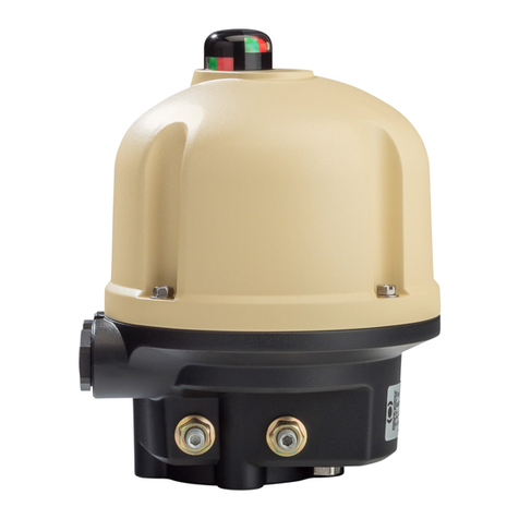
Bernard Controls AQ SWITCH 150-1000 User guide

AQ SWITCH 150-1000
RANGE
Start Up Guide
SUG_19010_EN_FR_ZH_ES - Ind. A
Art : 5100802

2

3
YOUR LANGUAGE
ENGLISH -------------------------------------------------------------- 5
FRANÇAIS ------------------------------------------------------------27
中文 ------------------------------------------------------------------50
ESPAÑOL-------------------------------------------------------------76

4

5
TABLE OF CONTENTS
DEFINITIONS---------------------------------------------------------- 7
1SAFETY ---------------------------------------------------------- 8
2PACKAGING, STORAGE AND MAINTENANCE----------------- 8
2.1 Packaging-------------------------------------------------- 8
2.2 Storage----------------------------------------------------- 8
2.3 Maintenance----------------------------------------------- 9
2.4 Actuator protection -------------------------------------- 9
3ACTUATOR INSTALLATION -----------------------------------10
3.1 Lifting -----------------------------------------------------10
3.2 Mounting / Unmounting of the socket----------------11
3.3 Fastening actuator on the valve-----------------------12
4ELECTRICAL COMMISSIONING --------------------------------12
4.1 Components (with cover open)------------------------12
4.2 Before wiring---------------------------------------------13
4.3 Wiring -----------------------------------------------------14
4.4 After wiring ----------------------------------------------15
4.5 Heating resistor------------------------------------------15
4.6Wiring the external ground terminal -----------------15
5TRAVEL LIMIT SETTINGS--------------------------------------16
5.1 Single cam setting---------------------------------------16
5.2 Cams setting ---------------------------------------------18
6POSITION INDICATOR SETTINGS -----------------------------18
6.1 Handling position indication ---------------------------18
6.2 Opening / Closing position indicator -----------------19
6.3 Setting indicator-----------------------------------------20

6
6.4 Changing closing direction indication ----------------21
7TORQUE LIMITING DEVICE------------------------------------21
7.1 Torque limiter operation-------------------------------21
7.2 Torque limiter adjustment-----------------------------22
8EMERGENCY MANUAL COMMAND ----------------------------23
9POSITION OPTIONS SETTINGS -------------------------------23
9.1 Position feedback ---------------------------------------23
9.2 Positioner (OPTION)-------------------------------------25

7
DEFINITIONS
Tip or info.
Warning requiring a check and/or a compulsory action.
!
Warning requiring a check and/or a compulsory action on
the device because of risks of damages for the device or
danger for the staff working on the device.

8
1SAFETY
This device complies with current applicable safety standards.
Installation, maintenance, and use of this unit require a skilled and trained
staff.
Please carefully read this whole document before mounting and starting-up
the actuator.
2PACKAGING, STORAGE AND MAINTENANCE
2.1 Packaging
AQ actuators packaging is comprised of a dual-layer carton strapped on a pallet.
For certain non-EU countries or on request, the pallets are heat treated to
standard NIMP 15 and IPPC-stamped.
This packaging is identical for shipping by road, air or sea, unless otherwise
provided in the contract.
2.1.1 Check identification sticker
Information on the nameplate sticker on the side of the actuator should match
those on your order.
QR Code on this sticker can be used to identify the actuator.
2.2 Storage
Actuators should be stored under a shelter, in a clean and dry place and at a
stable ambient temperature.
•Avoid placing the actuator directly on the floor
•Check that plugs of cable entries are correctly tightened.
•Check that cover screws are correctly tightened to ensure weatherproof
sealing of the cover.
AQ actuators include electrical components and lubricated gear stages. Even
with a weatherproof enclosure, oxidation, seizing and other alterations may
occur if actuator is not correctly stored.
Heating resistor should be connected to power supply especially if the storage
place is located outdoors.

9
What to check after storage
1. Visually check the electrical equipment.
2. Manually operate buttons, selectors, etc., to ensure their
proper mechanical functionality.
3. Manually operate the actuator for a few travels.
What to check on pre-installed actuators
If you expect a long period between actuator mounting andelectrical wiring:
visually check that cable entries and cover are tightly closed.
2.3 Maintenance
All AQ actuators feature lifetime lubrication and therefore require
no specific maintenance, if they were correctly commissioned and
used in conditions foreseen by design.
2.4 Actuator protection
Protection scale is defined according to the IEC529 standard.
AQ 150-1000 actuators fulfill the following requirements:
IP68 (Standard): full protectionagainst dust and water in case of underwater
continuous use with standard conditions of pressure and duration.
Manufacturer and user must acknowledge on a test to set-up.
Higher protection is necessary if the actuator is likely to be repeatedly
immerged.

10
3ACTUATOR INSTALLATION
3.1 Lifting
The actuators are lifted using slings (see figure below).
The specifications for these slings must be suitable for the weight of the
actuators (allow for an additional 50%).
According to the weight of the valve, ensure that the new centre of gravity
does not tilt the unit.
!
Never lift the valve by the actuator.
Never lift an actuator by its handwheel: it may be twisted or broken by its
own weight, and its shaft damaged.
When an actuator is installed on a valve, the slings must be mounted on the
valve and not on the actuator.
Gearbox
Actuator

11
3.2 Mounting / Unmounting of the socket
All AQ 150-1000 are delivered with
removable spline socket. It inserts into
the wheel and allows a precise
positioning between the actuator and
valve shaft.
Indicator position shows if default
position of the actuator is opened
(OPEN) or closed (CLOSE).
How to mount socket on valve
1. Turn over the actuator to see underneath the gearbox side.
2. To get the largest length of spline engaged, check end to
insert first in the gearbox: smooth end or splined end.
3. Bring closer this end of the socket to the gearbox.
4. Position the keyway of the socket to match the
corresponding keyway of the wheel (OPEN or CLOSE
according to default position).
5. Insert the socket into the wheel splines.
6. Put the circlip in place to hold the socket in place.
How to remove socket
1. Remove the circlip with the circlip pliers.
2. Remove the spline socket.
If alignment cannot be obtained, it could result from a wrong positioning.

12
3.3 Fastening actuator on the valve
Actuator should be secured directly to the valve using proper bolts or via a
proper interface.
After assembly, the actuator can operate in any position.
4ELECTRICAL COMMISSIONING
4.1 Components (with cover open)
9–Cable entry plugs
8–Ground terminal
7–Heating resistor
6–Terminal blocks
5–Torque limiter
4–Capacitor
3–Modular reduction
gear
2- End position cams
1- Position indicator
Actuator and its components are wired to internal terminal blocks.
However:
•do not handle the actuator by handwheel to avoid damage on actuator
gearing.
•cable glands must not be orientedupwards (loss of water tightness).
•It is recommended not to position motor downwards.
!
Ensure power wires are not supplied with electric power before wiring is
finished and the control compartment is closed.
If you need to open control compartment, previously cut off power supply to
the actuator.
4
5
6
7
8
9
3
2
1

13
4.2 Before wiring
To proceed to the electrical commissioning, you need :
1. to open the cover
2. to install cable glands
3. to wire the actuator
See Appendix for more information on the wiring.
4.2.1 Opening and closing the control compartment
You need to open the control compartment and remove the cover in order
to wire actuator.
How to open the cover
1. With 10mm angled socket
wrench or flat blade
screwdriver, unscrew the
4 screws from the housing.
2. Pull out the cover along its
axis.
3. Remove the cover
completely.
How to close the cover
1. Position the cover with the indicator window opposite the
position indicator.
2. Insert the cover on the position indicator until it reaches the
housing.
3. With 10mm angled socket wrench or flat blade screwdriver,
tighten the 4 screws on the housing.
!
•The electrical connection of the appliance must be carried out by a
qualified professional. All interventions inside the appliance must be
carried out by a qualified professional.
•In case of incorrect installation, there is a risk of electric shock and
damage to the device.

14
4.2.2 Installing cable glands
AQ Switch 150-1000 actuators are fitted with 3×M20 cable entries.
Cable glands must not be oriented upwards (loss of water tightness).
How to install cable glands
For each cable entry used
1. Remove plug from the cable
entry with 23mm (M20 entry)
open-end wrench.
2. Separate sealing nut from its
cable gland.
3. Screw and tighten cable gland
in the cable entry.
4. Thread the sealing nut on the cable and pass the cable through
the cable gland.
4.3 Wiring
How to wire actuator
The wiring must be done according to the wiring diagram of your actuator.
See Appendix for more information on the wiring.
1. Using a 3×0.5mm flat blade screwdriver, connect power supply
on terminals according to your wiring diagram.
2. Crimp a ring cable lug on the ground cable.
3. Using a 4 mm Allen key, remove the screw.
4. Install a washer between the head of the screw and the ring
cable lug.
5. Tighten the screw.
6. Tighten sealing nut on the cable gland when you have
completed wiring.
Unused entries must be kept closed by their plugs as they are part of the
components allowing actuator IP68 protection setting.
Both thermal protector and torque limit switches must be integrated into
your control system to prevent potential damage to the actuator or valve.

15
4.4 After wiring
What to check after wiring
Once actuator wiring is completed, please check the following:
1. Make sure that power supply voltage matches information on
the sticker on the side of the actuator.
2. Check that all connectors or cable glands are correctly
tightened.
3. Manually drive the valve to a mid-travel position.
4. Electrically operate counterclockwise rotation and check
that the motor rotates in the right direction.
5. Manually press on the counterclockwise end position switch
then the motor should stop.
6. Repeat steps 4 and 5 for clockwise direction.
If any fault is detected at this stage, please check that your wiring is correct.
4.5 Heating resistor
Each actuator includes a heating resistor.
As soon as the actuator is installed in the field and power off, it is necessary
to supply the resistor to prevent condensation.
•Immediately put the cover back in place after installation while ensuring
its seal is clean. Never leave actuator electrical components without
their protection cover.
In case of water intrusion:
•dry electrical components before putting back the cover.
•check electrical insulation.
4.6 Wiring the external ground terminal
How to wire the external ground terminal
1. Crimp the end of the earth cable with
a 6mm ring lug.
2. Fix it on the housing using a 5mm Allen
key, at its location next to the cable
entries.

16
5TRAVEL LIMIT SETTINGS
To limit the travel, AT actuator features a set of cams. Theytrigger switches
to switch off power at end positions, or to signal a position.
5.1 Single cam
setting
Cams rotate as the output shaft,
and trigger switches by pushing
on their levers.
Orientation of each cam is
factory pre-set, yet you can still
re-adjust them at the
installation if necessary.
Rep.
Function
Status before installation
1
Clockwise travel limit
Pre-wired, cam pre-set
2
Counter-clockwise travel limit
Pre-wired, cam pre-set
3
Clockwise signaling
Pre-wired, cam pre-set
4
Counter-clockwise signaling
Pre-wired, cam pre-set

17
How to adjust a single cam
At the desired position of the actuator output:
1. Turn the setting screw of
the corresponding cam
with a flat blade or a
Philips screwdriver.
7. The cam disk is then
turning.
2. Set the cam disk until you
hear a click from the
switch. It indicates the
trigger of the switch.
Always set a cam from the
same side according to the
accessible screw side.
CW replaces clockwise
CCW replaces counterclockwise
Left side
8. Right side
See TPF_0016 for more details on cams setting.
Make sure that cams get to the switch lever according to its inclination
direction, otherwise you could damage the switch.

18
5.2 Cams setting
The actuator stops on open or closed position when corresponding travel limit
switch is tripped by its cam.
How to adjust cams for both directions
1. Drive the valve to the clockwise travel limit position.
As a standard, it is CLOSED position.
2. Set the cam corresponding to clockwise travel limit switch
(1).
3. Drive the output slightly in the counter-clockwise direction
using manual override.
4. Set the cam corresponding to clockwise signaling switch (2).
5. Drive the actuator to the counter-clockwise travel limit
position.
6. Redo settings steps 2 to 4 for counter-clockwise direction.
7. Perform complete valve counter-clockwise and clockwise
electrical operations.
The motor should stop when the corresponding cams are
reached.
6POSITION INDICATOR SETTINGS
6.1 Handling position indication
Position indication can indicate travels
from 90°to 300°. Angle sector (gray
arrow) is marked out by 2 markers hold
on 2 rotating rings: (2a) red tagged “C”
(CLOSED) and (2b) green marker
tagged “O” (OPEN).
Position indicator (1) features a slit on
his side to indicate the current position
between CLOSED and OPEN positions.
It can be turned to be better viewed in
operation using flat blade screwdriver
shape on its top. The angle sector can
follow and be set according to position
indicator.

19
6.2 Opening / Closing position indicator
To open indicator, unscrew black ring of the indicator transparent cap (3)
and remove it.
To close indicator, put back the transparent cap (3) on indicator base and
screw the black ring on the base.
You do not have to remove the actuator cover to set the indicator.
Make sure that the actuator cap is correctly reassembled on its base,
otherwise actuator tightness is not guaranteed anymore.

20
6.3 Setting indicator
To set position indicator
1. Open indicator as shown on previous page.
2. Operate the actuatorelectrically towards CLOSE position until it stops
on end position switch.
3. Set the position indicator position if necessary.
4. Set the “C” marker in front of the indicator slit.
5. Operate the actuator electrically towards OPEN position until it stops
on end position switch.
6. Set the “O” marker in front of the indicator slit.
Table of contents
Languages:
Other Bernard Controls Controllers manuals
Bernard Controls
Bernard Controls FSE Series User guide

Bernard Controls
Bernard Controls Gamme FQ Series Installation manual
Bernard Controls
Bernard Controls ST Series Installation manual

Bernard Controls
Bernard Controls AQL Range User guide

Bernard Controls
Bernard Controls AT SWITCH RANGE User guide
Bernard Controls
Bernard Controls AQ Logic Series User guide
Bernard Controls
Bernard Controls EZ Series Instructions for use

Bernard Controls
Bernard Controls SQX Series Installation manual
Bernard Controls
Bernard Controls SD Series Instructions for use
Bernard Controls
Bernard Controls AQ Logic Series User guide